8.5. Thermal effect of current
8.5.1. Current source power
Total power of the current source:
P total = P useful + P losses,
where P is useful - useful power, P useful = I 2 R ; P losses - power losses, P losses = I 2 r; I - current strength in the circuit; R - load resistance (external circuit); r is the internal resistance of the current source.
Total power can be calculated using one of three formulas:
P full = I 2 (R + r), P full = ℰ 2 R + r, P full = I ℰ,
where ℰ is the electromotive force (EMF) of the current source.
Net power- this is the power that is released in the external circuit, i.e. on a load (resistor), and can be used for some purposes.
Net power can be calculated using one of three formulas:
P useful = I 2 R, P useful = U 2 R, P useful = IU,
where I is the current strength in the circuit; U is the voltage at the terminals (clamps) of the current source; R - load resistance (external circuit).
Power loss is the power that is released in the current source, i.e. in the internal circuit, and is spent on processes taking place in the source itself; The power loss cannot be used for any other purposes.
Power loss is usually calculated using the formula
P losses = I 2 r,
where I is the current strength in the circuit; r is the internal resistance of the current source.
During a short circuit, the useful power goes to zero
P useful = 0,
since there is no load resistance in the event of a short circuit: R = 0.
The total power during a short circuit of the source coincides with the loss power and is calculated by the formula
P full = ℰ 2 r,
where ℰ is the electromotive force (EMF) of the current source; r is the internal resistance of the current source.
Useful power has maximum value in the case when the load resistance R is equal to the internal resistance r of the current source:
R = r.
Maximum useful power:
P useful max = 0.5 P full,
where Ptot is the total power of the current source; P full = ℰ 2 / 2 r.
Explicit formula for calculation maximum useful power as follows:
P useful max = ℰ 2 4 r .
To simplify the calculations, it is useful to remember two points:
- if with two load resistances R 1 and R 2 the same useful power is released in the circuit, then internal resistance current source r is related to the indicated resistances by the formula
r = R 1 R 2 ;
- if the maximum useful power is released in the circuit, then the current strength I * in the circuit is doubled less strength short circuit current i:
I * = i 2 .
Example 15. When shorted to a resistance of 5.0 Ohms, a battery of cells produces a current of 2.0 A. The short circuit current of the battery is 12 A. Calculate the maximum useful power of the battery.
Solution . Let us analyze the condition of the problem.
1. When a battery is connected to a resistance R 1 = 5.0 Ohm, a current of strength I 1 = 2.0 A flows in the circuit, as shown in Fig. a, determined by Ohm’s law for the complete circuit:
I 1 = ℰ R 1 + r,
where ℰ - EMF of the current source; r is the internal resistance of the current source.
2. When the battery is short-circuited, a short-circuit current flows in the circuit, as shown in Fig. b. The short circuit current is determined by the formula
where i is the short circuit current, i = 12 A.
3. When a battery is connected to a resistance R 2 = r, a current of force I 2 flows in the circuit, as shown in Fig. in , determined by Ohm's law for the complete circuit:
I 2 = ℰ R 2 + r = ℰ 2 r;
in this case, the maximum useful power is released in the circuit:
P useful max = I 2 2 R 2 = I 2 2 r.
Thus, to calculate the maximum useful power, it is necessary to determine the internal resistance of the current source r and the current strength I 2.
In order to find the current strength I 2, we write the system of equations:
i = ℰ r , I 2 = ℰ 2 r )
and divide the equations:
i I 2 = 2 .
This implies:
I 2 = i 2 = 12 2 = 6.0 A.
In order to find the internal resistance of the source r, we write the system of equations:
I 1 = ℰ R 1 + r, i = ℰ r)
and divide the equations:
I 1 i = r R 1 + r .
This implies:
r = I 1 R 1 i − I 1 = 2.0 ⋅ 5.0 12 − 2.0 = 1.0 Ohm.
Let's calculate the maximum useful power:
P useful max = I 2 2 r = 6.0 2 ⋅ 1.0 = 36 W.
Thus, the maximum usable power of the battery is 36 W.
OHM'S LAW FOR A COMPLETE CIRCUIT:
I is the current strength in the circuit; E is the electromotive force of the current source connected to the circuit; R - external circuit resistance; r is the internal resistance of the current source.
POWER DELIVERED IN THE EXTERNAL CIRCUIT
![]() . (2)
. (2)
From formula (2) it is clear that in the event of a short circuit ( R®0) and at R® this power is zero. For all other final values R power R 1 > 0. Therefore, the function R 1 has a maximum. Meaning R 0, corresponding to the maximum power, can be obtained by differentiating P 1 with respect to R and equating the first derivative to zero:
 . (3)
. (3)
From formula (3), taking into account the fact that R and r are always positive, and E? 0, after simple algebraic transformations we get:
Hence, the power released in the external circuit reaches its greatest value when the resistance of the external circuit is equal to the internal resistance of the current source.
In this case, the current strength in the circuit (5)
equal to half the short circuit current. In this case, the power released in the external circuit reaches its maximum value equal to
When the source is closed to an external resistance, then current flows inside the source and at the same time a certain amount of heat is released at the internal resistance of the source. The power expended to release this heat is equal to
Consequently, the total power released in the entire circuit is determined by the formula
= I 2(R+r) = I.E. (8)
EFFICIENCY
EFFICIENCY current source is equal ![]() . (9)
. (9)
From formula (8) it follows that
those. R 1 changes with the change in current in the circuit according to a parabolic law and takes zero values at I = 0 and at . The first value corresponds to an open circuit (R>> r), the second to a short circuit (R<< r). Зависимость к.п.д. от силы тока в цепи с учётом формул (8), (9), (10) примет вид
Thus, the efficiency reaches its highest value h =1 in the case of an open circuit (I = 0), and then decreases according to a linear law, becoming zero in the case of a short circuit.
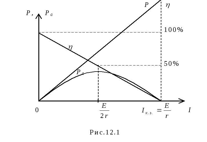
Dependence of powers P 1, P full = EI and efficiency. current source and the current strength in the circuit are shown in Fig. 1.

Fig.1. I 0 E/r
From the graphs it is clear that to obtain both useful power and efficiency. impossible. When the power released in the external section of the circuit P 1 reaches its greatest value, efficiency. at this moment it is 50%.
METHOD AND PROCEDURE OF MEASUREMENTS

Assemble the circuit shown in Fig. on the screen. 2. To do this, first click the left mouse button above the emf button. at the bottom of the screen. Move the mouse marker to the working part of the screen where the dots are located. Click the left mouse button in the working part of the screen where the emf source will be located.
Next, place a resistor in series with the source, representing its internal resistance (by first pressing the button at the bottom of the screen) and an ammeter (the button is in the same place). Then arrange the load resistors and voltmeter in the same way, measuring the voltage across the load.
Connect the connecting wires. To do this, click the wire button at the bottom of the screen, and then move the mouse marker to the working area of the circuit. Click with the left mouse button in the areas of the working area of the screen where the connecting wires should be located.
4. Set parameter values for each element. To do this, left-click on the arrow button. Then click on this element. Move the mouse marker to the slider of the regulator that appears, click on the left mouse button and, holding it down, change the parameter value and set the numerical value indicated in Table 1 for your option.
Table 1. Initial parameters of the electrical circuit
|
option |
||||||||
5. Set the external circuit resistance to 2 Ohms, press the “Count” button and write down the readings of electrical measuring instruments in the corresponding lines of Table 2.
6. Use the regulator slider to consistently increase the resistance of the external circuit by 0.5 Ohms from 2 Ohms to 20 Ohms and, pressing the “Count” button, record the readings of electrical measuring instruments in Table 2.
7. Calculate using formulas (2), (7), (8), (9) P 1, P 2, P total and h for each pair of voltmeter and ammeter readings and write the calculated values in Table 2.
8. Construct on one sheet of graph paper graphs of the dependence P 1 = f (R), P 2 = f (R), P total = f (R), h = f (R) and U = f (R).
9. Calculate the measurement errors and draw conclusions based on the results of the experiments.
Table 2. Results of measurements and calculations
|
P full, VT |
|||||||
Questions and tasks for self-control
- Write the Joule-Lenz law in integral and differential forms.
- What is short circuit current?
- What is gross power?
- How is efficiency calculated? current source?
- Prove that the greatest useful power is released when the external and internal resistances of the circuit are equal.
- Is it true that the power released in the internal part of the circuit is constant for a given source?
- A voltmeter was connected to the flashlight battery terminals, which showed 3.5 V.
- Then the voltmeter was disconnected and a lamp was connected in its place, on the base of which it was written: P = 30 W, U = 3.5 V. The lamp did not burn.
- Explain the phenomenon.
- When the battery is alternately shorted to resistances R1 and R2, an equal amount of heat is released in them at the same time. Determine the internal resistance of the battery.
Definition
Power is a physical quantity that is used as the main characteristic of any device that is used to perform work. Net power can be used to complete the task.
The ratio of work ($\Delta A$) to the period of time during which it was completed ($\Delta t$) is called the average power ($\left\langle P\right\rangle $) for this time:
\[\left\langle P\right\rangle =\frac(\Delta A)(\Delta t)\left(1\right).\]
Instantaneous power, or more often simply power, is the limit of relation (1) at $\Delta t\to 0$:
Taking into account that:
\[\Delta A=\overline(F)\cdot \Delta \overline(r\ )\left(3\right),\]
where $\Delta \overline(r\ )$ is the movement of the body under the action of force $\overline(F)$, in expression (2) we have:
where $\ \overline(v)-$ is the instantaneous speed.
Efficiency
When performing necessary (useful) work, for example, mechanical work, it is necessary to perform a larger amount of work, since in reality there are resistance forces and part of the energy is subject to dissipation (dissipation). The efficiency of work is determined using the efficiency factor ($\eta $), while:
\[\eta =\frac(P_p)(P)\left(5\right),\]
where $P_p$ is useful power; $P$ - consumed power. From expression (5) it follows that the useful power can be found as:
Formula for useful power of current source
Let the electrical circuit consist of a current source having resistance $r$ and a load (resistance $R$). We find the power of the source as:
where $?$ is the EMF of the current source; $I$ - current strength. In this case, $P$ is the total power of the circuit.
Let's denote $U$ - the voltage on the external section of the circuit, then formula (7) will be presented in the form:
where $P_p=UI=I^2R=\frac(U^2)(R)(9)$ - useful power; $P_0=I^2r$ - loss power. In this case, the source efficiency is determined as:
\[\eta =\frac(P_p)(P_p+P_0)\left(9\right).\]
The maximum useful power (power at the load) is produced by the electric current if the external resistance of the circuit is equal to the internal resistance of the current source. Under this condition, the useful power is equal to 50\% of the total power.
During a short circuit (when $R\to 0;;U\to 0$) or in idle mode $(R\to \infty ;;I\to 0$) the useful power is zero.
Examples of problems with solutions
Example 1
Exercise. The efficiency of the electric motor is $\eta $ =42%. What will be its useful power if at a voltage of $U=$110 V a current of $I=$10 A flows through the motor?
Solution. As a basis for solving the problem, we take the formula:
We find the total power using the expression:
Substituting the right side of expression (1.2) into (1.1) we find that:
Let's calculate the required power:
Answer.$P_p=462$ W
Example 2
Exercise. What is the maximum useful power of the current source if its short circuit current is equal to $I_k$? When connected to a resistance current source $R$, a current of force $I$ flows through the circuit (Fig. 1).
Solution. According to Ohm's law, for a circuit with a current source we have:
where $\varepsilon$ is the EMF of the current source; $r$ is its internal resistance.
In case of a short circuit, we assume that the resistance of the external load is zero ($R=0$), then the short circuit current is equal to:
The maximum useful power in the circuit Fig. 1 will give electric current, provided:
Then the current in the circuit is equal to:
We find the maximum useful power using the formula:
We received a system of three equations with three unknowns:
\[\left\( \begin(array)(c) I"=\frac(\varepsilon)(2r), \\ I_k=\frac(\varepsilon)(r), \\ P_(p\ max)= (\left(I"\right))^2r \end(array) \left(2.6\right).\right.\]
Using the first and second equations of system (2.6) we find $I"$:
\[\frac(I")(I_k)=\frac(\varepsilon)(2r)\cdot \frac(r)(\varepsilon)=\frac(1)(2)\to I"=\frac(1 )(2)I_k\left(2.7\right).\]
We use equations (2.1) and (2.2) to express the internal resistance of the current source:
\[\varepsilon=I\left(R+r\right);;\ I_kr=\varepsilon \to I\left(R+r\right)=I_kr\to r\left(I_k+I\right)=IR \to r=\frac(IR)(I_k-I)\left(2.8\right).\]
Let us substitute the results from (2.7) and (2.8) into the third formula of system (2.6), the required power will be equal to:
Answer.$P_(p\ max)=(\left(\frac(1)(2)I_k\right))^2\frac(IR)(I_k-I)$
 (12.11)
A short circuit is a circuit operating mode in which the external resistance R= 0. At the same time
 (12.12)
Net power R A = 0.
Full power
 (12.13)
Dependency graph R A (I) is a parabola, the branches of which are directed downwards (Fig. 12.1). The same figure shows the dependence of the efficiency on the current strength.
Examples of problem solving
Task 1. The battery consists of n= 5 elements connected in series with E= 1.4 V and internal resistance r= 0.3 ohm each. At what current is the useful power of the battery equal to 8 W? What is the maximum usable power of the battery?
Given: Solution
n = 5 When connecting elements in series, the current in the circuit
E= 1.4 V  (1)
(1)
R A= 8 W From the useful power formula  let's express
external resistance R and substitute into formula (1)
I
-
?
 -?
-? 
after transformations we obtain a quadratic equation, solving which we find the value of the currents:


 A; I 2
=
A; I 2
=
 A.
A.
So, at currents I 1 and I 2 the useful power is the same. When analyzing the graph of the dependence of useful power on current, it is clear that when I 1 less power loss and higher efficiency.
Net power is maximum at R
=
n
r;
R
= 0,3 Ohm.
Ohm.


Answer:
I 1 = 2 A; I 2
=
 A; P amax =
  Tue
Tue
Task 2. The useful power released in the external part of the circuit reaches a maximum value of 5 W at a current of 5 A. Find the internal resistance and emf of the current source.
Given: Solution
P amax = 5 W Useful power  (1)
(1)
I= 5 A according to Ohm's law  (2)
(2)
Net power is maximum at R = r, then from
r
- ? E- ? formulas (1)  0.2 Ohm.
From formula (2) B.
Answer: r= 0.2 Ohm; E= 2 V.
Task 3. A generator with an EMF of 110V is required to transmit energy over a distance of 2.5 km via a two-wire line. Power consumption is 10 kW. Find the minimum cross-section of copper supply wires if power losses in the network should not exceed 1%.
Given: Solution
E = 110V Wire Resistance 
l= 510 3 m where - resistivity of copper; l– length of wires;
R A = 10 4 W S– section.
= 1.710 -8 Ohm. m Power consumption P a = I E, power lost
R etc = 100 W online P etc = I 2 R etc, and since in breeding and consumer
S - ? current the same, then

where 
Substituting the numerical values, we get
 m 2.
m 2.
Answer: S= 710 -3 m 2.
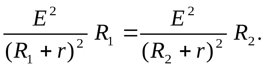
Task 4. Find the internal resistance of the generator if it is known that the power released in the external circuit is the same for two values of external resistance R 1 = 5 ohms and R 2 = 0.2 Ohm. Find the generator efficiency in each of these cases.
Given: Solution
R 1 = R 2 The power released in the external circuit is P a = I 2 R. According to Ohm's law
R 1 = 5 ohms for closed circuit  Then
Then  .
.
R 2 = 0.2 Ohm Using the problem condition R 1 = R 2, we get
r
-?

Transforming the resulting equality, we find the internal resistance of the source r:
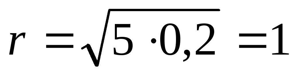 Ohm.
Ohm.
The efficiency factor is the quantity
 ,
,
Where R A– power released in the external circuit; R- full power.
Answer:
r= 1 Ohm;  =
83 %;
=
83 %; =
17 %.
=
17 %.
Task 5. EMF of battery E= 16 V, internal resistance r= 3 Ohm. Find the resistance of the external circuit if it is known that power is released in it R A= 16 W. Determine the efficiency of the battery.
Given: Solution
E= 16 V Power released in the external part of the circuit R A = I 2 R.
r
=
3 Ohm We find the current strength using Ohm's law for a closed circuit: 
R A= 16 W then  or
or 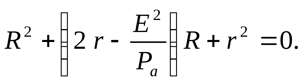
- ? R- ? We substitute the numerical values of the given quantities into this quadratic equation and solve it for R:
Ohm; R 2 = 9 ohms.
Answer: R 1 = 1 ohm; R 2 = 9 Ohm;
Task 6. Two light bulbs are connected to the network in parallel. The resistance of the first bulb is 360 Ohms, the resistance of the second is 240 Ohms. Which light bulb absorbs the most power? How many times?
Given: Solution
R 1 = 360 Ohm The power released in the light bulb is
R 2 = 240 Ohm P = I 2 R (1)
 -
?
With a parallel connection, the light bulbs will have the same voltage, so it’s better to compare powers by transforming formula (1) using Ohm’s law
-
?
With a parallel connection, the light bulbs will have the same voltage, so it’s better to compare powers by transforming formula (1) using Ohm’s law  Then
Then 

When bulbs are connected in parallel, more power is released into the bulb with lower resistance.
Answer:

Task 7. Two consumers with resistances R 1 = 2 ohms and R 2 = 4 Ohms are connected to the DC network the first time in parallel, and the second time in series. In what case is more power consumed from the network? Consider the case when R 1 = R 2 .
Given: Solution
R 1 = 2 Ohm Power consumption from the network
R 2 = 4 ohms  (1)
(1)
 -
?
Where R– general consumer resistance; U– network voltage. When connecting consumers in parallel, their total resistance
-
?
Where R– general consumer resistance; U– network voltage. When connecting consumers in parallel, their total resistance  and with sequential R
= R 1
+ R 2 .
and with sequential R
= R 1
+ R 2 .
In the first case, according to formula (1), the power consumption  and in the second
 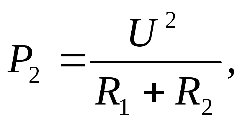 where
where 

Thus, when loads are connected in parallel, more power is consumed from the network than when connected in series.
At 
Answer:

Task 8.. The boiler heater consists of four sections, the resistance of each section is R= 1 Ohm. The heater is powered by a battery with E = 8 V and internal resistance r= 1 Ohm. How should the heater elements be connected so that the water in the boiler heats up in the shortest possible time? What is the total power consumed by the battery and its efficiency?
Given:
R 1 = 1 ohm
E = 8 V
r= 1 Ohm

Solution
The source provides maximum useful power if the external resistance R equal to internal r.
Therefore, in order for the water to heat up in the shortest possible time, the sections need to be turned on so
to R = r. This condition is met with a mixed connection of sections (Fig. 12.2.a, b).
The power consumed by the battery is R
= I
E. According to Ohm's law for a closed circuit  Then
Then 
Let's calculate  32 W;
32 W; 
Answer: R= 32 W; = 50 %.
Problem 9*. Current in a conductor with resistance R= 12 Ohm decreases uniformly from I 0 = 5 A to zero over time = 10 s. How much heat is released in the conductor during this time?
Given:
R= 12 Ohm
I 0 = 5 A
Q - ?
SolutionSince the current strength in the conductor changes, to calculate the amount of heat using the formula Q = I 2 R t cannot be used.
Let's take the differential dQ
=
I
2 R
dt, Then 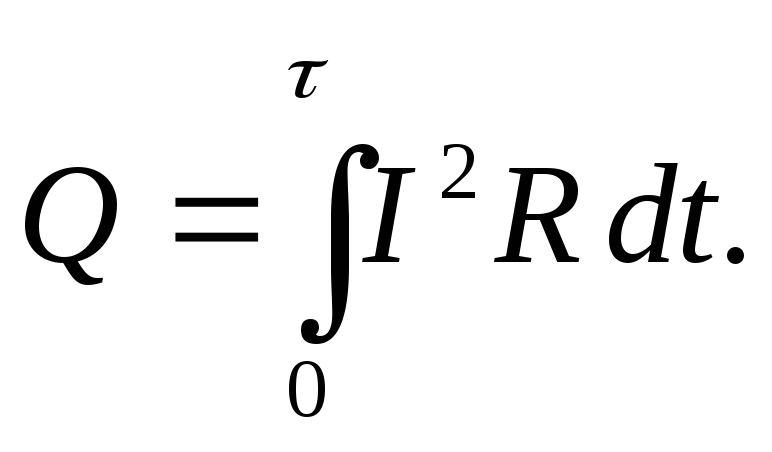 Due to the uniformity of the current change, we can write I
=
k
t, Where k– proportionality coefficient.
Due to the uniformity of the current change, we can write I
=
k
t, Where k– proportionality coefficient.
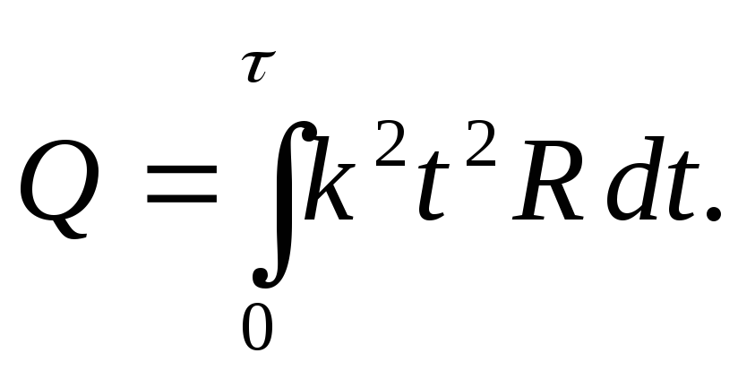
Proportionality factor value k we find from the condition that when
= 10 s current I 0 = 5 A, I 0
= k
, from here 

Let's substitute the numerical values:
 J.
J.
Answer: Q= 1000 J.
LABORATORY WORK No. 3.7.
STUDY OF USEFUL POWER AND EFFICIENCY OF CURRENT SOURCES
Last name I.O. _____________ Group ______ Date ______
Introduction
The purpose of this work is to experimentally test the theoretical conclusions about the dependence of the useful power and efficiency of the current source on the load resistance.
An electrical circuit consists of a current source, supply wires and a load or current consumer. Each of these circuit elements has resistance.
The resistance of the lead wires is usually very small, so it can be neglected. In each section of the circuit, the energy of the current source will be consumed. The question of the appropriate use of electrical energy is of very important practical importance.
The total power P released in the circuit will be the sum of the powers released in the external and internal parts of the circuit: P = I 2 R + I 2 r = I 2 (R + r). Because I(R + r) = ε, That Р =I·ε,
where R is external resistance; r – internal resistance; ε – EMF of the current source.
Thus, the total power released in the circuit is expressed by the product of the current and the emf of the element. This power is released due to any third-party energy sources; such energy sources can be, for example, chemical processes occurring in the element.
Let's consider how the power released in the circuit depends on the external resistance R to which the element is closed. Let us assume that an element of a given EMF and a given internal resistance r is closed by an external resistance R; Let us determine the dependence on R of the total power P allocated in the circuit, the power Ra allocated in the external part of the circuit and the efficiency.
The current strength I in the circuit is expressed according to Ohm's law by the relation
The total power released in the circuit will be equal to
As R increases, the power decreases, tending asymptotically to zero as R increases indefinitely.
The power released in the external part of the circuit is equal to
![]()
From this it can be seen that the useful power P a is equal to zero in two cases - at R = 0 and R = ∞.
Exploring the function R a = f(R) to the extremum, we find that P a reaches a maximum at R = r, then
To make sure that the maximum power P a is obtained at R = r, let’s take the derivative of P a with respect to external resistance
![]()
Where
![]()
According to the maximum condition, the first derivative must be equal to zero
 r 2 = R 2
![]() R = r
R = r
You can make sure that under this condition we will obtain a maximum, and not a minimum, for P a by determining the sign of the second derivative.
The efficiency factor (efficiency) η of an EMF source is the ratio of the power P a released in the external circuit to the total power P developed by the EMF source.
In essence, the efficiency of an EMF source indicates what proportion of the work of external forces is converted into electrical energy and transferred to the external circuit.
Expressing power in terms of current I, the potential difference in the external circuit U and the magnitude of the electromotive force ε, we obtain
That is, the efficiency of the EMF source is equal to the ratio of the voltage in the external circuit to the EMF. Under the conditions of applicability of Ohm's law, one can further replace U = IR; ε = I(R + r), Then
![]()
Consequently, in the case when all the energy is spent on Lenz-Joule heat, the efficiency of the EMF source is equal to the ratio of the external resistance to the total resistance of the circuit.
At R = 0 we have η = 0. With increasing R, the efficiency increases and tends to the value η = 1 with an unlimited increase in R, but at the same time the power released in the external circuit tends to zero. Thus, the requirements for simultaneously obtaining maximum useful power with maximum efficiency are impossible to meet.
When P a reaches its maximum, then η = 50%. When the efficiency η is close to unity, the useful power is small compared to the maximum power that a given source could develop. Therefore, to increase efficiency, it is necessary, if possible, to reduce the internal resistance of the EMF source, for example, a battery or a dynamo.
In the case of R = 0 (short circuit) P a = 0 and all the power is released inside the source. This can lead to overheating of the internal parts of the source and its failure. For this reason, short circuits of sources (dynamos, batteries) are not allowed!
In Fig. 1, curve 1 gives the dependence of the power P a released in the external circuit on the resistance of the external part of the circuit R; curve 2 gives the dependence of the total power P on R; curve 3 – variation of efficiency η from the same external resistance.
Work order
1. Check out the diagram at the stand.
2. Using the magazine, set the resistance R = 100 Ohm.
3. Close key K.
4. Measure the current in the circuit sequentially for nine different resistances on a resistance magazine, starting from 100 Ohms and above. Enter the results of current measurements into the table, expressing them in amperes.
5. Turn off key K.
6. Calculate for each resistance P, P a (in watts) and η.
7. Construct graphs of P, P a and η from R.
Control questions
1. What is the efficiency of an EMF source?
2. Derive the formula for the efficiency of the EMF source.
3. What is the useful power of an EMF source?
4. Derive the formula for the useful power of the EMF source.
5. What is the maximum power released in the external circuit (Pa)max?
6. At what value of R is the total power P released in the circuit maximum?
7. What is the efficiency of the EMF source at (Pa)max?
8. Carry out a study of the function (Pa) = f(R) to the extreme.
9. Draw a graph of the dependence of P, Ra and η on the external resistance R.
10. What is source emf?
11. Why should external forces be of non-electrical origin?
12. Why is short circuiting unacceptable for voltage sources?
|
No. |
R,Ohm |
I·10 -3 ,A |
, W |
, W |
|
|
1 |
0 |
||||
|
2 |
100 |
||||
|
3 |
200 |
||||
|
4 |
300 |
||||
|
5 |
400 |
||||
|
6 |
500 |
||||
|
7 |
600 |
||||
|
8 |
700 |
||||
|
9 |
800 |
||||
|
10 |
900 |
r = 300Ohm