Cooling the interior is the main function of an air conditioner, so the choice of air conditioner is determined primarily by the cooling capacity. In turn, the necessary air conditioner power directly depends on the size of the room that needs to be cooled.
WITH cooling capacity Power consumption should not be mixed, since these are completely different parameters. The cooling power is several times higher than the power consumed by the air conditioner. For example, an air conditioner consuming 700 W has a cooling power of 2 kW, and this should not be surprising, since the air conditioner works just like a refrigerator, the coolant (freon) takes heat from the air in the room and transfers it to the street through a heat exchanger (external unit of the air conditioner) . The power ratio is called air conditioner energy efficiency(EER). For household air conditioners, this parameter will have values in the range of 2.5 – 4.
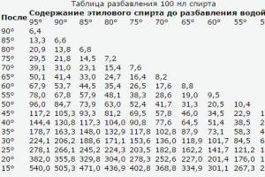
Below is the distribution table capacity air conditioners. Using it, you can select the types of air conditioners that are most optimal in certain conditions. For example, in small rooms or offices where low-power air conditioners are required, it is more rational to install mobile, window or wall-mounted models. Air conditioners other models have higher power and, accordingly, higher prices, so it is better to purchase them for cooling large premises (sales halls, warehouses, etc.)
| Cooling capacity, kW | 1.5 | 2 | 2.5 | 3.5 | 5.5 | 7 | 9 | 10 | 14 | 17 |
| Standard model sizes | 05 | 07 | 09 | 12 | 18 | 24 | 30 | 36 | 48 | 60 |
| Mobile air conditioners (mobile monoblocks and split systems) | ||||||||||
| Window air conditioners | ||||||||||
| Wall-mounted air conditioners | ||||||||||
| Cassette air conditioners | ||||||||||
| Duct air conditioners | ||||||||||
| Column air conditioners | ||||||||||
| Floor-ceiling air conditioners |
Power units
Quite often, in addition to the units of power measurement that are familiar to us, others are also used. For example, the British thermal unit, which is measured in BTU/h. It is determined by the amount of heat required to heat one pound of water per degree Fahrenheit.With the SI system it has the following relationship:
- 1W=3.4 BTU/h or
- 1000 BTU/h=293 W
How to calculate the power of an air conditioner
Power (more precisely, cooling power) is the main characteristic of any air conditioner. Approximate calculation of cooling power Q(in kilowatts) is produced according to generally accepted methods:
Q = Q1 + Q2 + Q3, Where Q1 heat inflows from windows, walls, floors and ceilings.Q1 = S * h * q / 1000, Where
S room area (sq. m);
h room height (m);
q coefficient equal to 30 - 40 W/kb. m:
q = 30 for a shaded room;
q = 35 at average illumination;
q = 40 for rooms that receive a lot of sunlight.
If the room receives direct sunlight, the windows should have light-colored curtains or blinds.
Q2 the sum of heat inflows from people.
Heat gain from an adult:
0.1 kW in a calm state;
0.13 kW with light movement;
0.2 kW during physical activity;
Q3 sum of heat inflows from household appliances.
Heat gains from household appliances:
0.3 kW from a computer;
0.2 kW from TV;
The power of the selected air conditioner should be in the range from -5% before +15% design power Q. Note that calculating an air conditioner using this method is not very accurate and is applicable only for small rooms in permanent buildings: apartments, individual rooms of cottages, office premises with an area of up to 50 - 70 square meters. m. For administrative, commercial and industrial facilities, other methods are used that take into account a larger number of parameters.
An example of calculating the power of an air conditioner
Let's calculate the power of the air conditioner for a living room with an area of 26 square meters. m with a ceiling height of 2.75 m in which one person lives, and also has a computer, TV and a small refrigerator with a maximum power consumption of 165 W. The room is located on the sunny side. The computer and TV do not work at the same time, since they are used by one person.
- First, we determine the heat inflows from the window, walls, floor and ceiling. Coefficient q let's choose equal 40
, since the room is located on the sunny side:
Q1 = S * h * q / 1000 = 26 sq. m * 2.75 m * 40 / 1000 = 2.86 kW.
- Heat inflows from one person at rest will be 0.1 kW.
Q2 = 0.1 kW
- Next, let’s find heat inflows from household appliances. Since the computer and TV do not work at the same time, only one of these devices needs to be taken into account in the calculations, namely the one that generates more heat. This is a computer whose heat output is 0.3 kW. The refrigerator emits about 30% of its maximum power consumption as heat, i.e. 0.165 kW * 30% / 100% ≈ 0.05 kW.
Q3 = 0.3 kW + 0.05 kW = 0.35 kW
- Now we can determine the estimated power of the air conditioner:
Q = Q1 + Q2 + Q3 = 2.86 kW + 0.1 kW + 0.35 kW = 3.31 kW
- Recommended power range Q range(from -5%
before +15%
design power Q):
3.14 kW< Q range < 3,80 кВт
All we have to do is choose a model of suitable power. Most manufacturers produce split systems with capacities close to the standard range: 2,0 kW; 2,6 kW; 3,5 kW; 5,3 kW; 7,0 kW. From this series we choose a model with a capacity 3,5 kW.
It is interesting that models from this series are often called “7” (seven), “9” (nine), “12”, “18” “24” and even the marking of air conditioners is carried out using these numbers, which reflect the power of the air conditioner in a way other than the usual kilowatts, and in BTU/hour. This is due to the fact that the first air conditioners appeared in the USA, where the British system of units (inches, pounds) is still used. For the convenience of buyers, the power of the air conditioner was expressed in round numbers: 7000 BTU/h, 9000 BTU/h, etc. The same numbers were used to label the air conditioner so that its power could be easily determined by its name. However, some manufacturers, such as Daikin, tie model names to power expressed in watts, so the Daikin FTY35 air conditioner has a power of 3.5 kW.
Additional parameters to consider when choosing an air conditioner
There are many factors that have a significant impact when choosing an air conditioner. First of all, it is necessary to take into account the role of fresh air flow when opening a window. The simplified method for calculating air conditioner power does not take into account opening windows for ventilation. This is due to the fact that even the operating instructions for the system indicate that the air conditioner should only operate with the windows closed. In turn, this creates certain inconveniences, since windows can only be ventilated when the device is turned off.Solving this problem is not difficult. You can ventilate the room with the air conditioner on at any time, but you should not forget to close the entrance door to the room (so as not to create drafts). It is also necessary to take this nuance into account when calculating the power of the system. To this end Q1 increase by 20% to compensate for the heat load from the supply air. It is necessary to understand that with an increase in power, electricity costs will also increase. For this reason, air conditioners are not recommended for use when ventilating rooms. At the highest possible temperature (summer heat), the air conditioner may not maintain the set temperature, since the heat influx may be too strong.
If the cooled room is located on the top floor, where there is no attic, then heat from the heated roof will be transferred into the room. Heat inflows from the ceiling will be much higher than from the walls, so we increase the power Q1 by 15%.
The large glass area of the windows also plays a significant role. It's pretty easy to follow. It is enough to measure the temperature in the sunny room and compare it with the others. During the usual calculation, the presence of a window in a room with an area of up to 2 m2 is provided. If the glazing area exceeds the permissible value. Then for every square meter of glazing an average of 100-200 W is added.
An inverter air conditioner is well suited to operate over a wide range of heat loads. It has variable cooling power, so it is able to create comfortable conditions in a given room.
Correspondence between model ranges and air conditioner power in BTU and kW
| The lineup | BTU | kW |
| 7 | 7000 BTU | 2.1 kW |
| 9 | 9000 BTU | 2.6 kW |
| 12 | 12000 BTU | 3.5 kW |
| 18 | 18000 BTU | 5.3 kW |
| 24 | 24000 BTU | 7.0 kW |
| 28 | 28000 BTU | 8.2 kW |
| 36 | 36000 BTU | 10.6 kW |
| 42 | 42000 BTU | 12.3 kW |
| 48 | 48000 BTU | 14.0 kW |
| 54 | 54000 BTU | 15.8 kW |
| 56 | 56000 BTU | 16.4 kW |
| 60 | 60000 BTU | 17.6 kW |
State Educational Institution of Higher Professional Education "Surgut State University"
Khanty-Mansiysk Autonomous Okrug - Ugra
Department of Life Safety
Course work
Topic: “Calculation of natural lighting”
Completed by: 04-42 group 5th year student
Faculty of Chemical Technology
Semenova Yulia Olegovna
Teacher:
Candidate of Chemical Sciences, Associate Professor
Andreeva Tatyana Sergeevna
The course work contains: 15 drawings, 9 tables, 2 sources used (including SP 23-102-2003 and SNiP 23-05-95), calculation formulas, calculations, plan and section of the room (sheet 1, sheet 2, format A 3).
Purpose of the work: determining the area of light openings, that is, the number and geometric dimensions of windows that provide the normalized value of KEO.
Object of study: office.
Volume of work: 41 pages.
Result of the work: the selected dimensions of the light opening meet the requirements of the standards for combined lighting of the office.
Introduction 4
Chapter 1. Types of natural lighting 5
Chapter 2. The principle of rationing natural light 6
Chapter 3. Designing natural lighting 9
Chapter 4. Calculation of natural lighting
4.1. Selecting daylight factor values 12
4.2. Preliminary calculation of the area of light openings and KEO with side lighting 13
4.3. Test calculation of KEO with side lighting 16
4.4. Preliminary calculation of the area of light openings and KEO with overhead lighting 19
4.5. Test calculation of KEO with overhead lighting 23
Chapter 5. Calculation of natural lighting in the office 29
Tables 32
Conclusion 39
References 40
Introduction
Premises with constant occupancy should have natural light.
Natural lighting - lighting of premises with direct or reflected light penetrating through light openings in external enclosing structures. Natural lighting should be provided, as a rule, in rooms with constant occupancy. Without natural lighting, it is allowed to design certain types of industrial premises in accordance with the Sanitary Standards for the Design of Industrial Enterprises.
Types of natural lighting
The following types of natural indoor lighting are distinguished:
side one-sided - when the light openings are located in one of the external walls of the room,
Figure 1 - Lateral one-way natural lighting
side - light openings in two opposite external walls of the room,

Figure 2 - Lateral natural lighting
· upper - when lanterns and light openings in the covering, as well as light openings in the walls of the height difference of the building,
·combined - light openings provided for side (top and side) and top lighting.
The principle of normalizing natural light
Natural lighting is used for general lighting of production and utility rooms. It is created by the radiant energy of the sun and has the most beneficial effect on the human body. When using this type of lighting, meteorological conditions and their changes during the day and periods of the year in a given area should be taken into account. This is necessary in order to know how much natural light will enter the room through the building's light openings: windows - with side lighting, skylights on the upper floors of the building - with overhead lighting. With combined natural lighting, side lighting is added to the overhead lighting.
Premises with constant occupancy should have natural light. The dimensions of light openings established by calculation can be changed by +5, -10%.
The unevenness of natural lighting in industrial and public buildings with overhead or overhead and natural side lighting and main rooms for children and adolescents with side lighting should not exceed 3:1.
Sun protection devices in public and residential buildings should be provided in accordance with the chapters of SNiP on the design of these buildings, as well as with the chapters on building heating engineering.
The quality of lighting with natural light is characterized by the coefficient of natural light to eo, which is the ratio of illumination on a horizontal surface indoors to the simultaneous horizontal illumination outside,
![]() ,
,
where E in is the horizontal illumination indoors in lux;
E n - horizontal illumination outside in lux.
With side lighting, the minimum value of the natural illumination coefficient is normalized - to eo min, and with overhead and combined lighting - its average value - to eo avg. The method for calculating the natural light factor is given in the Sanitary Standards for the Design of Industrial Enterprises.
In order to create the most favorable working conditions, natural light standards have been established. In cases where natural light is insufficient, work surfaces should be additionally illuminated with artificial light. Mixed lighting is allowed provided additional lighting of only working surfaces with general natural lighting.
Building codes and regulations (SNiP 23-05-95) set the coefficients of natural illumination of industrial premises depending on the nature of the work and the degree of accuracy.
To maintain the necessary illumination of the premises, the standards provide for mandatory cleaning of windows and skylights from 3 times a year to 4 times a month. In addition, walls and equipment should be systematically cleaned and painted in light colors.
The standards for natural lighting of industrial buildings, reduced to the K.E.O. standardization, are presented in SNiP 23-05-95. To facilitate the regulation of workplace illumination, all visual work is divided into eight categories according to the degree of accuracy.
SNiP 23-05-95 establish the required value of K.E.O. depending on the accuracy of the work, the type of lighting and the geographical location of the production. The territory of Russia is divided into five light belts, for which the values of K.E.O. are determined by the formula:
where N is the group number of the administrative-territorial district according to the provision of natural light;
The value of the natural illumination coefficient, selected according to SNiP 23-05-95, depending on the characteristics of visual work in a given room and the natural lighting system.
Light climate coefficient, which is found according to SNiP tables depending on the type of light openings, their orientation along the horizon and the group number of the administrative district.
To determine whether natural illumination in a production room corresponds to the required standards, illumination is measured with overhead and combined lighting at various points in the room, followed by averaging; at the side - at the least illuminated workplaces. At the same time, the external illumination and the calculated K.E.O. are measured. compared with the norm.
Natural Light Design
1. The design of natural lighting in buildings should be based on the study of labor processes performed indoors, as well as on the light-climatic features of the building construction site. In this case, the following parameters must be defined:
characteristics and category of visual work;
group of the administrative district in which the construction of the building is proposed;
the normalized value of KEO, taking into account the nature of visual work and the light-climatic features of the location of the buildings;
required uniformity of natural light;
the duration of use of natural light during the day for different months of the year, taking into account the purpose of the room, operating mode and light climate of the area;
the need to protect the premises from the glare of sunlight.
2. Design of natural lighting of a building should be carried out in the following sequence:
determination of requirements for natural lighting of premises;
choice of lighting systems;
selection of types of light openings and light-transmitting materials;
choosing means to limit the glare of direct sunlight;
taking into account the orientation of the building and light openings on the sides of the horizon;
performing a preliminary calculation of the natural lighting of the premises (determining the required area of light openings);
clarification of the parameters of light openings and rooms;
performing a verification calculation of the natural lighting of the premises;
identification of rooms, zones and areas that have insufficient natural lighting according to standards;
determination of requirements for additional artificial lighting of rooms, zones and areas with insufficient natural light;
determination of requirements for the operation of light openings;
making the necessary adjustments to the natural lighting design and repeating the verification calculation (if necessary).
3. The natural lighting system of the building (side, top or combined) should be selected taking into account the following factors:
the purpose and adopted architectural, planning, volumetric and structural design of the building;
requirements for natural lighting of premises arising from the peculiarities of production technology and visual work;
climatic and light-climatic features of the construction site;
efficiency of natural lighting (in terms of energy costs).
4. Overhead and combined natural lighting should be used mainly in one-story public buildings of large area (indoor markets, stadiums, exhibition pavilions, etc.).
5. Lateral natural lighting should be used in multi-story public and residential buildings, one-story residential buildings, as well as in one-story public buildings in which the ratio of the depth of the premises to the height of the upper edge of the light opening above the conventional working surface does not exceed 8.
6. When choosing light openings and light-transmitting materials, you should consider:
requirements for natural lighting of premises;
purpose, volumetric-spatial and structural design of the building;
orientation of the building along the horizon;
climatic and light climatic features of the construction site;
the need to protect premises from insolation;
degree of air pollution.
7. When designing side natural lighting, shading created by opposing buildings should be taken into account.
8. Translucent fillings of light openings in residential and public buildings are selected taking into account the requirements of SNiP 23-02.
9. For side natural lighting of public buildings with increased requirements for constant natural lighting and sun protection (for example, art galleries), light openings should be oriented towards the northern quarter of the horizon (N-NW-N-NE).
10. The selection of devices for protection from the glare of direct sunlight should be made taking into account:
orientation of light openings on the sides of the horizon;
the direction of the sun's rays relative to a person in the room who has a fixed line of sight (student at his desk, draftsman at the drawing board, etc.);
working hours of the day and year, depending on the purpose of the premises;
the difference between solar time, according to which solar maps are constructed, and maternity time adopted on the territory of the Russian Federation.
When choosing means to protect against the glare of direct sunlight, you should be guided by the requirements of building codes and regulations for the design of residential and public buildings (SNiP 31-01, SNiP 2.08.02).
11. During a single-shift work (educational) process and when operating premises mainly in the first half of the day (for example, lecture halls), when the premises are oriented towards the western quarter of the horizon, the use of sunscreen is not necessary.
Calculation of natural light
The purpose of calculating natural lighting is to determine the area of light openings, that is, the number and geometric dimensions of windows that provide the normalized KEO value.
Selecting KEO values
1. In accordance with SNiP 23-05, the territory of the Russian Federation is zoned into five groups of administrative districts according to light climate resources. The list of administrative districts included in the natural light supply groups is given in Table 1.
2. KEO values in residential and public buildings located in the first group of administrative districts are taken in accordance with SNiP 23-05.
3. KEO values in residential and public buildings located in the second, third, fourth and fifth groups of administrative districts are determined by the formula
e N = e n m N , (1)
Where N- number of the group of administrative districts according to Table 1;
e n- normalized value of KEO according to Appendix I SNiP 23-05;
m N- light climate coefficient, taken according to Table 2.
The values obtained using formula (1) should be rounded to tenths.
4. The dimensions and location of light openings in the room, as well as compliance with the requirements of the standards for natural lighting of premises, are determined by preliminary and verification calculations.
Preliminary calculation of the area of light openings and KEO with side lighting
1. A preliminary calculation of the size of light openings with side lighting without taking into account opposing buildings should be carried out using the graphs given for premises of residential buildings in Figure 3, for premises of public buildings - in Figure 4, for school classrooms - in Figure 5. The calculation should be made in following sequence:

Drawing 3 - Graph for determining the relative area of light openings A s.o /A p with side lighting of residential premises

Drawing 4 - Graph for determining the relative area of light openings A s.o /A p with side lighting of public buildings

Drawing 5 - Graph for determining the relative area of light openings A s.o /A p with side lighting of school classrooms
a) depending on the category of visual work or the purpose of the premises and the group of administrative districts for the light climate resources of the Russian Federation according to SNiP 23-05, determine the normalized value of KEO for the premises in question;
d P h 01 and attitude d P /h 01 ;
c) on the x-axis of the graph (Figures 3, 4 or 5) determine the point corresponding to a certain value d P /h 01, a vertical line is drawn through the found point until it intersects with the curve corresponding to the normalized KEO value. The ordinate of the intersection point determines the value A s.o /A p ;
d) dividing the found value A s.o /A p by 100 and multiplying by the floor area, find the area of light openings in m2.
2. In the case when the dimensions and location of light openings in the building design were chosen for architectural and construction reasons, a preliminary calculation of the KEO values in the premises should be made according to Figures 3-5 in the following sequence:
a) using construction drawings, find the total area of light openings (clear) A s.o and illuminated floor area of the room A p and determine the attitude A s.o /A p ;
b) determine the depth of the room d P, the height of the upper edge of the light openings above the level of the conditional working surface h 01 and attitude d P /h 01 ;
c) taking into account the type of premises, select the appropriate schedule (Figures 3, 4 or 5);
d) by values A s.o /A p And d P /h 01 on the graph find a point with the corresponding KEO value.
The graphs (Figures 3-5) were developed in relation to the most common dimensional layouts of premises in design practice and the standard solution for translucent structures - wooden paired opening frames.
Test calculation of KEO with side lighting
1. Check calculation of KEO Calculation of KEO should be carried out in the following sequence:
a) graph I (Figure 6) is superimposed on the cross section of the room so that its pole (center) 0 aligns with the design point A(Figure 8), and the bottom line of the graph is with a trace of the working surface;
b) according to graph I, count the number of rays passing through the cross section of the light opening from the sky n 1 and from the opposing building to the design point A ;
c) mark the numbers of semicircles on graph I that coincide with the middle WITH 1 section of the light opening through which the sky is visible from the calculated point, and with the middle WITH 2 sections of light opening through which the opposing building is visible from the calculated point (Figure 8);
d) schedule II (Figure 7) is superimposed on the floor plan so that its vertical axis and the horizontal, the number of which corresponds to the number of the concentric semicircle (point “c”), pass through the point WITH 1 (Figure 8);
e) count the number of rays P 2 according to schedule II, passing from the sky through the light opening on the floor plan to the design point A ;
f) determine the value of the geometric KEO, taking into account direct light from the sky;
g) schedule II is superimposed on the floor plan in such a way that its vertical axis and horizontal line, the number of which corresponds to the number of the concentric semicircle (point “c”), pass through the point WITH 2 ;
h) count the number of rays according to schedule II passing from the opposing building through the light opening on the floor plan to the calculated point A ;
i) determine the value of the geometric coefficient of natural illumination, taking into account the light reflected from the opposing building;
j) determine the value of the angle at which the middle of the sky section is visible from the calculated point on the cross section of the room (Figure 9);
k) based on the value of the angle and the specified parameters of the room and surrounding buildings, the values of the coefficients are determined q i , b f , k ZD , r O, And K h, and calculate the KEO value at the design point of the room.

Drawing 6- Graph I for calculating geometric KEO

Drawing 7 - Graph II for calculating geometric KEO
Notes
1 Graphs I and II are applicable only for rectangular light openings.
2 The plan and section of the room are made (drawn) on the same scale.

A- design point; 0 - pole of graph I; WITH 1 - the middle of the section of the light opening through which the sky is visible from the calculated point; WITH 2 - the middle of the section of the light opening through which the opposing building is visible from the calculated point
Drawing 8 - Example of using graph I to count the number of rays from the sky and the opposing building
Preliminary calculation of the area of light openings and KEO with overhead lighting
1. To preliminary calculate the area of light openings with overhead lighting, the following graphs should be used: for skylights with an opening depth (light shaft) of up to 0.7 m - according to Figure 9; for mine lights - according to Figures 10, 11; for rectangular, trapezoidal lanterns, sheds with vertical glazing and sheds with inclined glazing - according to Figure 12.
Table 1
| Fill type | Coefficient values K 1 for graphs in figures | |
| 1 | 2, 3 | |
| One layer of window glass in steel single blind sash | - | 1,26 |
| The same, in opening bindings | - | 1,05 |
| Single layer of window glass in wooden single opening sash | 1,13 | 1,05 |
| Three layers of window glass in separate-paired metal opening frames | - | 0,82 |
| The same, in wooden bindings | 0,63 | 0,59 |
| Two layers of window glass in steel double opening sashes | - | 0,75 |
| The same, in blind bindings | - | - |
| Double-glazed windows (two layers of glazing) in steel single opening frames* | - | 1,00 |
| The same, in blind bindings* | - | 1,15 |
| Double-glazed windows (three layers of glazing) in solid steel twin frames* | - | 1,00 |
| Hollow glass blocks | - | 0,70 |
| * When using other types of bindings (PVC, wood, etc.) coefficient K 1 is taken according to Table 3 before carrying out the appropriate tests. | ||
Area of light openings of lamps A s.f determined from the graphs in Figures 9-12 in the following sequence:
a) depending on the category of visual work or the purpose of the premises and group of administrative districts for the light climate resources of the Russian Federation according to SNiP 23-05;
b) on the ordinate of the graph, a point corresponding to the normalized value of KEO is determined, a horizontal line is drawn through the found point until it intersects with the corresponding curve of the graph (Figures 9-12), the value is determined from the abscissa of the intersection point A s.f /A p ;
c) dividing the value A s.f /A p by 100 and multiplying by the floor area, find the area of the light openings of the lamps in m2.
Preliminary calculation of KEO values in premises should be made using the graphs in Figures 9-12 in the following sequence:
a) using the construction drawings, find the total area of the light openings of the lamps A s.f, illuminated floor area of the room A p and determine the attitude A s.f /A p ;
b) taking into account the type of lantern, select the appropriate pattern (8, 10, 11 or 12);
c) in the selected picture through the abscissa point A s.f /A p draw a vertical line until it intersects with the corresponding graph; the ordinate of the intersection point will be equal to the calculated average value of the daylight factor e cf .

Drawing 9 - Graph for determining the average KEO value e cf in rooms with skylights with an opening depth of up to 0.7 m and dimensions in plan, m:
1 - 2.9x5.9; 2 3 - 1.5x1.7

Drawing 10 - Graph for determining the average KEO value e cf in public premises with shaft lamps with a light-conducting shaft depth of 3.50 m and plan dimensions, m:
1 - 2.9x5.9; 2 - 2.7x2.7; 2.9x2.9; 1.5x5.9; 3 - 1.5x1.7

Drawing 11 - Graph for determining the average KEO value e cf in public spaces with shaft lamps of diffuse light with a light-conducting shaft depth of 3.50 m and dimensions in plan, m:
1 - 2.9x5.9; 2 - 2.7x 2.7; 2.9x2.9; 1.5x5.9; 3 - 1.5x1.7

1 - trapezoidal lantern; 2 - shed having inclined glazing;
3 - rectangular lantern; 4 - a shed with vertical glazing
Drawing 12- Graph for determining the average KEO value e cp in public areas with lanterns
Test calculation of KEO with overhead lighting
The KEO calculation is carried out in the following sequence:
a) graph I (Figure 6) is applied to the cross section of the room so that the pole (center) 0 of the graph is aligned with the calculated point, and the bottom line of the graph is aligned with the trace of the working surface. Count the number of radially directed rays of graph I passing through the cross section of the first opening ( n 1) 1, second opening - ( n 1) 2, third opening - ( n 1) 3, etc.; at the same time, the numbers of semicircles that pass through the middle of the first, second, third openings, etc. are noted;
b) determine the angles , , etc. between the bottom line of graph I and the line connecting the pole (center) of graph I with the middle of the first, second, third openings, etc.;
c) schedule II (Figure 7) is applied to a longitudinal section of the room; in this case, the graph is positioned so that its vertical axis and horizontal, the number of which must correspond to the number of the semicircle on graph I, pass through the middle of the opening (point C).
Count the number of rays according to schedule II passing through the longitudinal section of the first opening ( n 2) 1, second opening - ( P 2) 2, third opening - ( n 2) 3, etc.;
d) calculate the value of the geometric KEO at the first point of the characteristic section of the room using the formula
Where R- number of light openings;
q- coefficient taking into account the uneven brightness of the sky area visible from the first point, respectively, at angles ,, etc.;
e) repeat the calculations in accordance with points “a”, “b”, “c”, “d” for all points of the characteristic section of the room until N inclusive (where N- the number of points at which the KEO is calculated);
f) determine the average value of the geometric KEO;
g) based on the given parameters of the room and light openings, the values are determined r 2 , k f , ;
A verification calculation of KEO values at points of a characteristic section of a room with overhead lighting from skylights and mine lights should be performed according to the formula:
Where A f.v- area of the upper entrance hole of the lantern;
N f- number of lanterns;
q() is a coefficient that takes into account the uneven brightness of the cloudy sky of the ICO;
The angle between the straight line connecting the calculated point with the center of the lower hole of the lantern and the normal to this hole;
Average value of geometric KEO;
K With- light transmission coefficient of the lantern, determined for lanterns with diffuse reflection of the walls, and for lanterns with directional reflection of the walls - by the value of the mine lantern light opening index i f ;

Drawing 13 - Graph for determining the coefficient q() depending on the angle

Drawing 14 K With lamps with diffuse reflection of the shaft walls

Drawing 15 - Graph for determining the light transmission coefficient Kc lanterns with directional reflection of the shaft walls at different values of the diffuse reflection coefficient of the shaft walls
K h- a calculated coefficient that takes into account the decrease in KEO and illumination during operation due to contamination and aging of translucent fillings in light openings, as well as a decrease in the reflective properties of room surfaces (safety factor).
Light opening index of a lantern with rectangular holes i f determined by the formula
Where A f.n.- area of the lower opening of the lantern, m2;
A f.v- area of the upper opening of the lantern, m2;
h s.f- height of the light-conducting shaft of the lantern, m.
R f.v , R f.n.- perimeter of the upper and lower openings of the lantern, respectively, m.
The same, with holes in the shape of a circle - according to the formula
i f = (r f.v + r f.n.) / 2h s.f , (5)
Where r f.v , r f.n.- the radius of the upper and lower holes of the lantern, respectively.
Calculate the value of the geometric KEO at the first point of the characteristic section of the room using the formula
Repeat the calculations for all points of the characteristic section of the room until N j inclusive (where N j- the number of points at which the KEO calculation is performed).
Determined by formula
The direct component KEO is sequentially calculated for all points using the formula
Determine the reflected component KEO, the value of which is the same for all points, according to the formula
![]() . (9)
. (9)
Calculation of natural lighting in the office
Theoretical part
Lighting for workrooms and offices should be designed based on the following requirements:
a) creating the necessary lighting conditions on work tables located in the back of the room when performing a variety of visual work (reading typographic and typewritten texts, handwritten materials, distinguishing details of graphic materials, etc.);
b) providing visual connection with the external space;
c) protection of premises from the glare and thermal effects of insolation;
d) favorable distribution of brightness in the field of view.
Side lighting of work rooms should, as a rule, be provided by separate light openings (one window for each office). In order to reduce the required area of light openings, the height of the window sill above the floor level is recommended to be at least 0.9 m.
When the building is located in the administrative regions of the Russian Federation of light climate resource groups, the normalized value of KEO should be taken: with a depth of work rooms (offices) of 5 m or more - according to Table 3 in relation to the combined lighting system; less than 5 m - according to Table 4 in relation to the natural lighting system.
To ensure visual contact with the outside space, the filling of light openings should, as a rule, be done with translucent window glass.
To limit the glare of solar radiation in workrooms and offices, it is necessary to provide curtains and lightweight adjustable blinds. When designing control buildings and office buildings for the III and IV climatic regions of the Russian Federation, it is necessary to provide for the installation of light openings oriented to the horizon sector within 200°-290° with sun protection devices.
In premises, the reflectance values of surfaces must be no less than:
ceiling and top of walls.. 0.70
the bottom of the walls................... 0.50
floor........................................ 0.30.
Practical part
It is required to determine the required window area in the work rooms of the management building located in the city of Surgut (sheet 1).
Original data. Room depth d P= 5.5 m height h= 3.0 m width b P= 3.0 m, floor area A p= 16.5 m 2, height of the upper edge of the light opening above the conditional working surface h 01 = 1.9 Filling light openings with transparent glazing over metal single frames; the thickness of the external walls is 0.35 m. There is no shading by opposing buildings.
Solution
1. Considering that the depth of the room d P over 5 m, according to Table 3 we find that the normalized value of KEO is 0.5%.
2. We make a preliminary calculation of natural lighting based on the initial depth of the room d P= 5.5 m and the height of the upper edge of the light opening above the conditional working surface h 01 = 1.9 m; determine that d P /h 01 = 5,5/1,9=2,9.
3. In Figure 4 on the corresponding curve e= 0.5% find the point with the abscissa d P /h 01 = 2.9. From the ordinate of this point we determine that the required relative area of the light opening A O / A P = 16,6%.
4. Determine the area of the light opening Oh according to the formula:
0,166 A p= 0.166 · 16.5 = 2.7 m2.
Therefore, the width of the light opening b o= 2.7/1.8 = 1.5 m.
We accept a window block measuring 1.5 x 1.8 m.
5. We carry out a verification calculation of the KEO at the point A(sheet 1) according to the formula:
![]() .
.
6. We superimpose graph I for calculating the KEO using the A.M. method. Danilyuk on a cross section of the room (sheet 2), combining the pole of the graph I - 0 with the point A, and the bottom line - with a conditional working surface; We count the number of rays according to graph I passing through the cross section of the light opening: n 1 = 2.
7. We note that through the point WITH on the section of the room (sheet 2) there is a concentric semicircle 26 of schedule I.
8. We superimpose graph II for calculating KEO on the floor plan (sheet 1) so that its vertical axis and horizontal 26 pass through the point WITH; Using graph II, we calculate the number of rays passing from the sky through the light opening: P 2 = 16.
9. Determine the value of the geometric KEO using the formula:
10. On a cross-section of the room on a scale of 1:50 (sheet 2), we determine that the middle of the sky section visible from the calculated point A through the light opening is at an angle ; Based on the value of this angle in Table 5, we find a coefficient that takes into account the uneven brightness of the cloudy sky of the CIE: q i =0,64.
11. Based on the dimensions of the room and the light opening, it is found that d P /h 01 = 2,9;
l T /d P = 0,82; b P /d P = 0,55.
12. Weighted average reflectance .
13. Based on the found values d P /h 01 ; l T /d P ; b P /d P according to table 6 we find that r o = 4,25.
14. For transparent glazing with a metal single frame, we find the total light transmittance.
15 According to SNiP 23-05 we find that the safety factor for windows of public buildings K h = 1,2.
16 We determine the geometric KEO at point A by substituting the values of all found coefficients into the formula:
![]() .
.
Consequently, the selected dimensions of the light opening meet the requirements of the standards for combined lighting of the office.
Table 1
Groups of administrative districts
| Administrative region | |
| 1 | Moscow, Smolensk, Vladimir, Kaluga, Tula, Ryazan, Nizhny Novgorod, Sverdlovsk, Perm, Chelyabinsk, Kurgan, Novosibirsk, Kemerovo regions, Republic of Mordovia, Chuvash Republic, Udmurt Republic, Republic of Bashkortostan, Republic of Tatarstan, Krasnoyarsk Territory (north of 63° N. sh.). Republic of Sakha (Yakutia) (north of 63° N), Chukotka Autonomous Region. Okrug, Khabarovsk Territory (north of 55° N) |
| 2 | Bryansk, Kursk, Orel, Belgorod, Voronezh, Lipetsk, Tambov, Penza, Samara, Ulyanovsk, Orenburg, Saratov, Volgograd regions, Komi Republic, Kabardino-Balkarian Republic, North Ossetia-Alania Republic, Chechen Republic, Ingushetia Republic, Khanty-Mansiysk Autonomous Okrug, Altai Republic, Krasnoyarsk Territory (south of 63° N), Republic of Sakha (Yakutia) (south of 63° N), Republic of Tyva, Republic of Buryatia, Chita Region, Khabarovsk Territory (south of 55° N. sh.), Magadan, Sakhalin regions |
| 3 | Kaliningrad, Pskov, Novgorod, Tver, Yaroslavl, Ivanovo, Leningrad, Vologda, Kostroma, Kirov regions, Republic of Karelia, Yamalo-Nenets Autonomous Okrug, Nenets Autonomous Okrug |
| 4 | Arkhangelsk, Murmansk regions |
| 5 | Republic of Kalmykia, Rostov, Astrakhan regions, Stavropol Territory, Krasnodar Territory, Republic of Dagestan, Amur Region, Primorsky Territory |
table 2
Light climate coefficient
| Light openings | Orientation of light openings along the horizon | Light climate coefficient m N | ||||
| Administrative district group number | ||||||
| 1 | 2 | 3 | 4 | 5 | ||
| In the outer walls of the building | WITH | 1 | 0,9 | 1,1 | 1,2 | 0,8 |
| NE, NW | 1 | 0,9 | 1,1 | 1,2 | 0,8 | |
| Z, V | 1 | 0,9 | 1,1 | 1,1 | 0,8 | |
| SE, SW | 1 | 0,85 | 1 | 1,1 | 0,8 | |
| YU | 1 | 0,85 | 1 | 1,1 | 0,75 | |
| In skylights | - | 1 | 0,9 | 1,2 | 1,2 | 0,75 |
| Note - C - northern; NE - northeast; NW - northwestern; B - eastern; W - western; Yu - southern; SE - southeast; SW - southwest orientation. | ||||||
Table 3
Normalized KEO values for side combined lighting in the main premises of residential and public buildings in administrative districts of various light climate resource groups
| Groups of administrative districts by light climate resources | KEO, % | |||||
| in school classes | in exhibition halls | in reading rooms | in the design rooms | |||
| 1 | 0,60 | 1,30 | 0,40 | 0,70 | ||
| 0,60 | 1,30 | 0,40 | 0,70 | |||
| 159-203 | 0,60 | 1,30 | 0,40 | 0,70 | ||
| 294-68 | 0,60 | - | 0,40 | 0,70 | ||
| 2 | 0,50 | 1,20 | 0,40 | 0,60 | ||
| 0,50 | 1,10 | 0,40 | 0,60 | |||
| 159-203 | 0,50 | 1,10 | 0,40 | 0,60 | ||
| 294-68 | 0,50 | - | 0,40 | 0,60 | ||
| 3 | 0,70 | 1,40 | 0,50 | 0,80 | ||
| 0,60 | 1,30 | 0,40 | 0,70 | |||
| 159-203 | 0,60 | 1,30 | 0,40 | 0,70 | ||
| 294-68 | 0,70 | - | 0,50 | 0,90 | ||
| 4 | 0,70 | 1,40 | 0,50 | 0,80 | ||
| 0,70 | 1,40 | 0,50 | 0,80 | |||
| 159-203 | 0,70 | 1,40 | 0,50 | 0,80 | ||
| 294-68 | 0,70 | - | 0,50 | 0,80 | ||
| 5 | 0,50 | 1,00 | 0,30 | 0,60 | ||
| 0,50 | 1,00 | 0,30 | 0,60 | |||
| 159-203 | 0,50 | 1,00 | 0,30 | 0,50 | ||
| 294-68 | 0,50 | - | 0,30 | 0,60 | ||
Table 4
Normalized values of KEO with lateral natural lighting in the main premises of residential and public buildings in various groups of administrative districts according to light climate resources
Admin groups rational areas according to light climate resources |
Orientation of light openings along the sides of the horizon, degrees. | Normalized KEO values, % | |||||
| in work rooms of management buildings, offices | in school classes | in residential premises |
vocal halls |
in reading rooms | in design rooms, drawing- design- trade bureaus |
||
| 1 | 1,00 | 1,50 | 0,50 | 0,70 | 1,20 | 1,50 | |
| 1,00 | 1,50 | 0,50 | 0,70 | 1,20 | 1,50 | ||
| 159-203 | 1,00 | 1,50 | 0,50 | 0,70 | 1,20 | 1,50 | |
| 294-68 | 1,00 | - | 0,50 | 0,70 | 1,20 | 1,50 | |
| 2 | 0,90 | 1,40 | 0,50 | 0,60 | 1,10 | 1,40 | |
| 0,90 | 1,30 | 0,40 | 0,60 | 1,10 | 1,30 | ||
| 159-203 | 0,90 | 1,30 | 0,40 | 0,60 | 1,10 | 1,30 | |
| 294-68 | 0,90 | - | 0,50 | 0,60 | 1,10 | 1,40 | |
| 3 | 1,10 | 1,70 | 0,60 | 0,80 | 1,30 | 1,70 | |
| 1,00 | 1,50 | 0,50 | 0,70 | 1,20 | 1,50 | ||
| 159-203 | 1,00 | 1,50 | 0,50 | 0,70 | 1,20 | 1,50 | |
| 294-68 | 1,10 | - | 0,60 | 0,80 | 1,30 | 1,70 | |
| 4 | 1,10 | 1,70 | 0,60 | 0,80 | 1,30 | 1,70 | |
| 1,10 | 1,70 | 0,60 | 0,80 | 1,30 | 1,70 | ||
| 159-203 | 1,10 | 1,70 | 0,60 | 0,80 | 1,30 | 1,70 | |
| 294-68 | 1,20 | - | 0,60 | 0,80 | 1,40 | 1,80 | |
| 5 | 0,80 | 1,20 | 0,40 | 0,60 | 1,00 | 1,20 | |
| 0,80 | 1,20 | 0,40 | 0,60 | 1,00 | 1,20 | ||
| 159-203 | 0,80 | 1,10 | 0,40 | 0,50 | 0,90 | 1,10 | |
| 294-68 | 0,80 | - | 0,40 | 0,60 | 0,90 | 1,20 | |
Table 5
Coefficient values q i
| Angular height of the middle ray of the sky section visible from the calculated point through the light opening in the section of the room, degrees. | Coefficient values q i |
| 2 | 0,46 |
| 6 | 0,52 |
| 10 | 0,58 |
| 14 | 0,64 |
| 18 | 0,69 |
| 22 | 0,75 |
| 26 | 0,80 |
| 30 | 0,86 |
| 34 | 0,91 |
| 38 | 0,96 |
| 42 | 1,00 |
| 46 | 1,04 |
| 50 | 1,08 |
| 54 | 1,12 |
| 58 | 1,16 |
| 62 | 1,18 |
| 66 | 1,21 |
| 70 | 1,23 |
| 74 | 1,25 |
| 78 | 1,27 |
| 82 | 1,28 |
| 86 | 1,28 |
| 90 | 1,29 |
Notes 1 For values of angular heights of the middle beam different from those given in the table, the values of the coefficient q i determined by interpolation. 2 In practical calculations, the angular height of the middle ray of the sky section, visible from the calculated point through the light opening in the section of the room, should be replaced by the angular height of the middle of the sky section, visible from the calculated point through the light opening. |
|
Table 6
Values r o for a conditional working surface
| Room depth ratio d P to the height from the level of the conventional working surface to the top of the window h 01 | Ratio of the distance of the design point from the inner surface of the outer wall l T to the depth of the room d P | Weighted average reflectance of floor, walls and ceiling | |||||||||||
| 0,60 | 0,50 | 0,45 | 0,35 | ||||||||||
| Room length ratio a p to its depth d P | |||||||||||||
| 0,5 | 1,0 | 2,0 | 0,5 | 1,0 | 2,0 | 0,5 | 1,0 | 2,0 | 0,5 | 1,0 | 2,0 | ||
| 1,00 | 0,10 | 1,03 | 1,03 | 1,02 | 1,02 | 1,02 | 1,02 | 1,02 | 1,02 | 1,01 | 1,01 | 1,01 | 1,01 |
| 1,00 | 0,50 | 1,66 | 1,59 | 1,46 | 1,47 | 1,42 | 1,33 | 1,37 | 1,34 | 1,26 | 1,19 | 1,17 | 1,13 |
| 1,00 | 0,90 | 2,86 | 2,67 | 2,30 | 2,33 | 2,19 | 1,93 | 2,06 | 1,95 | 1,74 | 1,53 | 1,48 | 1,37 |
| 3,00 | 0,10 | 1,10 | 1,09 | 1,07 | 1,07 | 1,06 | 1,05 | 1,06 | 1,05 | 1,04 | 1,03 | 1,03 | 1,02 |
| 3,00 | 0,20 | 1,32 | 1,29 | 1,22 | 1,23 | 1,20 | 1,16 | 1,18 | 1,16 | 1,13 | 1,09 | 1,08 | 1,06 |
| 3,00 | 0,30 | 1,72 | 1,64 | 1,50 | 1,51 | 1,46 | 1,36 | 1,41 | 1,37 | 1,29 | 1,20 | 1,18 | 1,14 |
| 3,00 | 0,40 | 2,28 | 2,15 | 1,90 | 1,91 | 1,82 | 1,64 | 1,73 | 1,66 | 1,51 | 1,37 | 1,33 | 1,26 |
| 3,00 | 0,50 | 2,97 | 2,77 | 2,38 | 2,40 | 2,26 | 1,98 | 2,12 | 2,01 | 1,79 | 1,56 | 1,51 | 1,39 |
| 3,00 | 0,60 | 3,75 | 3,47 | 2,92 | 2,96 | 2,76 | 2,37 | 2,57 | 2,41 | 2,10 | 1,78 | 1,71 | 1,55 |
| 3,00 | 0,70 | 4,61 | 4,25 | 3,52 | 3,58 | 3,32 | 2,80 | 3,06 | 2,86 | 2,44 | 2,03 | 1,93 | 1,72 |
| 3,00 | 0,80 | 5,55 | 5,09 | 4,18 | 4,25 | 3,92 | 3,27 | 3,60 | 3,34 | 2,82 | 2,30 | 2,17 | 1,91 |
| 3,00 | 0,90 | 6,57 | 6,01 | 4,90 | 4,98 | 4,58 | 3,78 | 4,18 | 3,86 | 3,23 | 2,59 | 2,43 | 2,11 |
| 5,00 | 0,10 | 1,16 | 1,15 | 1,11 | 1,12 | 1,11 | 1,08 | 1,09 | 1,08 | 1,07 | 1,05 | 1,04 | 1,03 |
| 5,00 | 0,20 | 1,53 | 1,48 | 1,37 | 1,38 | 1,34 | 1,27 | 1,30 | 1,27 | 1,21 | 1,15 | 1,14 | 1,11 |
| 5,00 | 0,30 | 2,19 | 2,07 | 1,84 | 1,85 | 1,77 | 1,60 | 1,68 | 1,61 | 1,48 | 1,34 | 1,31 | 1,24 |
| 5,00 | 0,40 | 3,13 | 2,92 | 2,49 | 2,52 | 2,37 | 2,07 | 2,22 | 2,10 | 1,85 | 1,61 | 1,55 | 1,43 |
| 5,00 | 0,50 | 4,28 | 3,95 | 3,29 | 3,34 | 3,11 | 2,64 | 2,87 | 2,68 | 2,31 | 1,94 | 1,84 | 1,66 |
| 5,00 | 0,60 | 5,58 | 5,12 | 4,20 | 4,27 | 3,94 | 3,29 | 3,61 | 3,35 | 2,83 | 2,31 | 2,18 | 1,92 |
| 5,00 | 0,70 | 7,01 | 6,41 | 5,21 | 5,29 | 4,86 | 4,01 | 4,44 | 4,09 | 3,40 | 2,72 | 2,55 | 2,20 |
| 5,00 | 0,80 | 8,58 | 7,82 | 6,31 | 6,41 | 5,87 | 4,79 | 5,33 | 4,90 | 4,03 | 3,17 | 2,95 | 2,52 |
| 5,00 | 0,90 | 10,28 | 9,35 | 7,49 | 7,63 | 6,96 | 5,64 | 6,30 | 5,77 | 4,71 | 3,65 | 3,39 | 2,86 |
If the surface finish of the room is unknown, then for the premises of residential and public buildings the weighted average reflectance coefficient should be taken equal to 0.50.
Table 7
Values of coefficients 1 and
| Type of light transmitting material | Values |
Type of binding | Values |
| Window sheet glass: | Bindings for windows and skylights of industrial buildings: | ||
| single | 0,9 | ||
| double | 0,8 | wooden: | |
| triple | 0,75 | single | 0,75 |
| Display glass 6-8 mm thick | 0,8 | paired | 0,7 |
| Reinforced sheet glass | 0,6 | double separate | 0,6 |
| Patterned sheet glass | 0,65 | steel: | |
| Sheet glass with special properties: | single opening | 0,75 | |
| single deaf | 0,9 | ||
| sun protection | 0,65 | double opening | 0,6 |
| contrasting | 0,75 | double deaf | 0,8 |
| Organic glass: | Casements for windows of residential, public and auxiliary buildings: | ||
| transparent | 0,9 | ||
| dairy | 0,6 | ||
| Hollow glass blocks: | wooden: | ||
| light-scattering | 0,5 | single | 0,8 |
| translucent | 0,55 | paired | 0,75 |
| Double-glazed windows | 0,8 | double separate | 0,65 |
| with triple glazing | 0,5 | ||
| metal: | |||
| single | 0,9 | ||
| paired | 0,85 | ||
| double separate | 0,8 | ||
| with triple glazing | 0,7 | ||
| Glass-reinforced concrete panels with hollow glass blocks with seam thickness: | |||
| 20 mm or less | 0,9 | ||
| more than 20 mm | 0,85 |
Table 8
Coefficient values and
| Load-bearing structures of coatings | A coefficient that takes into account light loss in supporting structures, | Sun protection devices, products and materials | A coefficient that takes into account light loss in solar shading devices, |
| Steel trusses | 0,9 | Retractable adjustable blinds and curtains (interglazed, internal, external) | 1,0 |
| Reinforced concrete and wooden trusses and arches | 0,8 | Stationary blinds and screens with a protective angle of no more than 45° when the blinds or screens are located at an angle of 90° to the window plane: | |
| horizontal | 0,65 | ||
| vertical | 0,75 | ||
| Beams and frames are solid with section height: | Horizontal visors: | ||
| with a protective angle of no more than 30° | 0,8 | ||
| 50 cm or more | 0,8 | with a protective angle from 15° to 45° | 0,9-0,6 |
| less than 50 cm | 0,9 | (multistage) | |
| Balconies depth: | |||
| up to 1.20 m | 0,90 | ||
| 1.50 m | 0,85 | ||
| 2.00 m | 0,78 | ||
| 3.00 m | 0,62 | ||
| Loggias depth: | |||
| up to 1.20 m | 0,80 | ||
| 1.50 m | 0,70 | ||
| 2.00 m | 0,55 | ||
| 3.00 m | 0,22 |
Conclusion
During my course work, I studied such a parameter as natural lighting. The principle of rationing natural lighting, as well as the design of natural lighting, was considered. In this work, I calculated the natural lighting in the office. The normalized value of the natural light factor is 0.5% for the selected district. Having made a preliminary calculation, I found out the dimensions of the window unit for sufficient illumination: 1.5 * 1.8. In the verification calculation, I confirmed the correctness of the chosen dimensions of the light opening, since they meet the requirements of the standards for combined lighting of the study. The coefficient of natural light in the verification calculation is 0.53%.
The living room has a significant impact on the sound quality of the main speakers and speakers. It doesn’t matter where in the room they are located. Thus, when installing speakers in the corner of the room, low frequencies rise, which is not always desirable, especially in the case of insufficient damping of the low frequencies of the GG. At the same time, for small speakers, raising the low frequencies enriches the sound. It is better to place the speakers along the larger wall of the room, away from the corners. Recommendations for placing speakers are not always feasible in a living room, since they may not be consistent with the arrangement of furniture, and therefore in each specific case you should try different options, assessing the sound quality by ear according to your taste. The acoustic conditions in a room have a strong impact on sound quality. In the extreme case, when there is no furniture in the living room, i.e. the room is empty, the sound of any speaker becomes completely unsatisfactory. The shape of the room is important. The least successful is cubic. In a room of any configuration, just like inside the acoustic design of speakers, standing waves arise at low frequencies. In cubic rooms, the intensity of standing waves is maximum, since they are formed at the same frequencies due to the equality of the distance between opposite walls. There are no effective methods for combating standing waves in residential premises, and therefore it is better to avoid placing speakers in cube-shaped rooms.
Living spaces are never empty; they always have upholstered furniture, books, carpets, i.e. the rooms have a significant fund for sound absorption of medium and high frequencies, which provides quite acceptable listening conditions. You can get some increase in the sound-absorbing fund by fixing the existing carpet not close to the wall, as usual, but at some distance from it, at least within 30...50 mm. If there are books in the room, located in cabinets or on glass bookshelves, then it is useful to open the cabinet doors and move the glass shelves while listening. The speakers should be installed in such a way that the high-frequency loudspeakers are located at eye level of the seated listener (at a height of 1.25 m from the floor). For stereophonic sound reproduction, it is also necessary to provide conditions for the best perception of the stereophonic effect in a place in the room convenient for listeners. For this purpose, the speakers must be installed at a distance of 1.5...2.5 m from each other so that their working axes intersect in the center of the listening area, which will be located in the middle between the speakers at the same distance from each of them, equal to the distance between them , and further. It should be noted the importance of correct mutual phasing of the speakers when connecting them to an audio amplifier. At home, the phasing of the speaker connections can be checked by installing them next to each other and feeding a monophonic music program containing pronounced low-frequency components into the electrical path. If, when changing the polarity of connecting any one speaker, the volume of low frequencies decreases sharply, then it means that the speakers were turned on in phase and it is necessary to restore the original polarity of connection. If, on the contrary, the volume of low frequencies increases, then this connection polarity should be left as correct.
Calculation of natural light
The purpose of calculating natural lighting is to determine the area of light openings, that is, the number and geometric dimensions of windows that provide the normalized KEO value.
Selecting KEO values
1. In accordance with SNiP 23-05, the territory of the Russian Federation is zoned into five groups of administrative districts according to light climate resources. The list of administrative districts included in the natural light supply groups is given in Table 1.
2. KEO values in residential and public buildings located in the first group of administrative districts are taken in accordance with SNiP 23-05.
3. KEO values in residential and public buildings located in the second, third, fourth and fifth groups of administrative districts are determined by the formula
e N = e n m N , (1)
Where N - according to table 1;
e n - normalized value of KEO according to Appendix I SNiP 23-05;
m N - light climate coefficient, taken according to Table 2.
The values obtained using formula (1) should be rounded to tenths.
4. The dimensions and location of light openings in the room, as well as compliance with the requirements of the standards for natural lighting of premises, are determined by preliminary and verification calculations.
Preliminary calculation of the area of light openings and KEO with side lighting
1. A preliminary calculation of the size of light openings with side lighting without taking into account opposing buildings should be carried out using the graphs given for premises of residential buildings in Figure 3, for premises of public buildings - in Figure 4, for school classrooms - in Figure 5. The calculation should be made in following sequence:

Drawing 3 A s.o / A P with side lighting of residential premises

Drawing 4 - Graph for determining the relative area of light openingsA s.o / A P with side lighting of public buildings

Drawing 5 - Graph for determining the relative area of light openingsA s.o / A P with side lighting of school classrooms
a) depending on the level of visual work or the purpose of the room andgroups of administrative districts for light climate resources of the Russian Federation according to SNiP 23-05 determine the normalized value of KEO for the premises in question;
d P h 01 and attitude d P / h 01 ;
c) on the x-axis of the graph (Figures 3, 4 or 5) determine the point corresponding to a certain valued P / h 01 a vertical line is drawn through the found point until it intersects with the curve corresponding to the normalized KEO value. The ordinate of the intersection point determines the valueA s.o / A P ;
d) dividing the found valueA s.o / A P by 100 and multiplying by the floor area, find the area of light openings in m 2 .
2. In the case when the dimensions and location of light openings in the building design were chosen for architectural and construction reasons, a preliminary calculation of the KEO values in the premises should be made according to Figures 3-5 in the following sequence:
a) using construction drawings, find the total area of light openings (clear)A s.o and illuminated floor area of the roomA P and determine the attitudeA s.o / A P ;
b) determine the depth of the roomd P , the height of the upper edge of the light openings above the level of the conditional working surfaceh 01 and attitude d P / h 01 ;
c) taking into account the type of premises, select the appropriate schedule (Figures 3, 4 or 5);
d) by values A s.o / A P And d P / h 01 find a point on the graph with the corresponding KEO value.
The graphs (Figures 3-5) were developed in relation to the most common dimensional layouts of premises in design practice and the standard solution for translucent structures - wooden paired opening frames.
Test calculation of KEO with side lighting
1. Check calculation of KEO Calculation of KEO should be carried out in the following sequence:
a) schedule Iplaced on the cross section of the room so that its pole (center) 0 aligns with the design pointA (Figure 8), and the bottom line of the graph is with a trace of the working surface;
b) according to schedule Icount the number of rays passing through the cross section of the light opening from the skyn
1
and from the opposing building  to the design pointA
; Design points are taken at a distance of 1 m from the surface of the walls (partitions).
to the design pointA
; Design points are taken at a distance of 1 m from the surface of the walls (partitions).
c) mark the numbers of semicircles on the graphI, coinciding with the middleWITH 1 section of the light opening through which the sky is visible from the calculated point, and with the middleWITH 2 the area of the light opening through which the opposing building is visible from the calculated point (Figure 8);
d) schedule II(Figure 7) are superimposed on the floor plan in such a way that its vertical axis and the horizontal, the number of which corresponds to the number of the concentric semicircle (point “c”), pass through the pointWITH 1 (Figure 8);
e) count the number of raysP 2 on schedule IIpassing from the sky through the light opening on the floor plan to the design pointA ;
f) determine the value of the geometric KEO, taking into account direct light from the sky;
g) schedule IIsuperimposed on the floor plan in such a way that its vertical axis and the horizontal, the number of which corresponds to the number of the concentric semicircle (point “c”), pass through the pointWITH 2 ;
h) count the number of rays on schedule II, passing from the opposing building through the light opening on the floor plan to the design pointA ;
i) determine the value of the geometric coefficient of natural illumination, taking into account the light reflected from the opposing building;
j) determine the value of the angle  , under which the middle of the sky section is visible from the calculated point on the cross section of the room;
k) by angle valueand the given parameters of the room and surrounding buildings determine the values of the coefficientsq
i
,
b
f
,
k
ZD
,
r
O
,
 And K
h
, and calculate the KEO value at the design point of the room.
And K
h
, and calculate the KEO value at the design point of the room.

Drawing 6 - Schedule I

Notes
1 Charts I And IIApplicable only to rectangular light openings. 2 The plan and section of the room are made (drawn) on the same scale.

A - design point; 0 - graph poleI; WITH 1 - the middle of the section of the light opening through which the sky is visible from the calculated point;
Preliminary calculation of the area of light openings and KEO with overhead lighting
To preliminary calculate the area of light openings with overhead lighting, the following graphs should be used: for skylights with an opening depth (light shaft) of up to 0.7 m - according to Figure 9; for mine lights - according to Figures 10, 11; for rectangular, trapezoidal lanterns, sheds with vertical glazing and sheds with inclined glazing - according to Figure 12.
Table 1
|
Fill type |
Coefficient valuesK 1 for graphs in pictures |
|
|
2, 3 |
||
|
One layer of window glass in steel single blind sash |
1,26 |
|
|
The same, in opening bindings |
1,05 |
|
|
Single layer of window glass in wooden single opening sash |
1,13 |
1,05 |
|
Three layers of window glass in separate-paired metal opening frames |
0,82 |
|
|
The same, in wooden bindings |
0,63 |
0,59 |
|
Two layers of window glass in steel double opening sashes |
0,75 |
|
|
The same, in blind bindings |
||
|
Double-glazed windows (two layers of glazing) in steel single opening frames* |
1,00 |
|
|
The same, in blind bindings* |
1,15 |
|
|
Double-glazed windows (three layers of glazing) in solid steel twin frames* |
1,00 |
|
|
Hollow glass blocks |
0,70 |
|
|
* When using other types of bindings (PVC, wood, etc.) coefficientK 1 taken according to Table 3 before conducting appropriate tests. |
||
Area of light openings of lampsA s.f determined from the graphs in Figures 9-12 in the following sequence:
a) depending on the category of visual work or the purpose of the premises and group of administrative districts for the light climate resources of the Russian Federation according to SNiP 23-05;
b) on the ordinate of the graph, a point corresponding to the normalized value of KEO is determined, a horizontal line is drawn through the found point until it intersects withthe corresponding curve of the graph (Figures 9-12), the abscissa of the intersection point determines the valueA s.f / A P ;
c) dividing the valueA s.f / A P by 100 and multiplying by the floor area, find the area of the light openings of the lamps in m 2 .
Preliminary calculation of KEO values in premises should be made using the graphs in Figures 9-12 in the following sequence:
a) using the construction drawings, find the total area of the light openings of the lampsA s.f , illuminated floor area of the roomA P and determine the attitudeA s.f / A P ;
b) taking into account the type of lantern, select the appropriate pattern (8, 10, 11 or 12);
c) in the selected picture through the abscissa pointA s.f / A P draw a vertical line until it intersects with the corresponding graph; the ordinate of the intersection point will be equal to the calculated average value of the daylight factore Wed .

Drawing 9 e Wed in rooms with skylights with an opening depth of up to 0.7 m and dimensions in plan, m:
1 — 2.9×5.9; 2 3 — 1.5×1.7

Drawing 10 - Graph for determining the average KEO valuee Wed in public premises with shaft lamps with a light-conducting shaft depth of 3.50 m and plan dimensions, m:
1 — 2.9×5.9; 2 - 2.7×2.7; 2.9×2.9; 1.5×5.9;3 — 1.5×1.7

Drawing 11 - Graph for determining the average KEO valuee Wed in public spaces with shaft lamps of diffuse light with a light-conducting shaft depth of 3.50 m and dimensions in plan, m:
1 — 2.9×5.9; 2 - 2.7x 2.7; 2.9×2.9; 1.5×5.9;3 — 1.5×1.7

1 - trapezoidal lantern;2 - shed having inclined glazing; 3 - rectangular lantern;4 - a shed with vertical glazing
Drawing 12 - Graph for determining the average KEO valuee cp in public areas with lanterns
Test calculation of KEO with overhead lighting
The KEO calculation is carried out in the following sequence:
a) schedule I(Figure 6) are applied to the cross section of the room so that the pole (center) 0 of the graph is aligned with the calculated point, and the bottom line of the graph is aligned with the trace of the working surface. Count the number of radially directed rays of the graphI, passing through the cross section of the first opening (n 1 ) 1 , second opening - (n 1 ) 2 , third opening - (n 1 ) 3 etc.; at the same time, the numbers of semicircles that pass through the middle of the first, second, third openings, etc. are noted;
b) determine the angles, , etc. between the bottom line of the graphIand a line connecting the pole (center) of the graphIwith the middle of the first, second, third openings, etc.;
c) schedule II(Figure 7) is applied to a longitudinal section of the room; atIn this case, the graph is positioned so that its vertical axis and horizontal line, the number of which must correspond to the number of the semicircle on the graphI, passed through the middle of the opening (pointC ). Count the number of rays according to the graphII, passing through the longitudinal section of the first opening (n 2 ) 1 , second opening - (P 2 ) 2 , third opening - (n 2) 3, etc.;
d) calculate the value of the geometric KEO, at the first point of the characteristic section of the room according to the formula
, (2)
Where R
- number of light openings;q
- coefficient taking into account the uneven brightness of the sky area visible from the first point, respectively, at angles  ,
,
 , etc.;
e) repeat the calculations in accordance with points “a”, “b”, “c”, “d” forall points of the characteristic section of the room up toN inclusive (whereN - the number of points at which the KEO is calculated);
f) determine the average value of the geometric KEO;
g) based on the given parameters of the room and light openings, the values are determinedr 2 , k f , ;
Verification calculation of KEO values at points of a characteristic section of a room with overhead lightingfrom anti-aircraft and mine lamps should be carried out according to the formula:
, (3)
Where A
f.v
- area of the upper entrance hole of the lantern;N
f- number of lanterns; q
(αε
 ) is a coefficient that takes into account the uneven brightness of the cloudy sky of the CIE; - the angle between the straight line connecting the calculated point with the center of the lower hole of the lantern and the normal to this hole;- average value of geometric KEO; K
With
- light transmission coefficient of the lantern, determined for lanterns with diffuse reflection of the walls, and for lanterns with directional reflection of the walls- according to the index value of the light opening of the mine lanterni
f
;
) is a coefficient that takes into account the uneven brightness of the cloudy sky of the CIE; - the angle between the straight line connecting the calculated point with the center of the lower hole of the lantern and the normal to this hole;- average value of geometric KEO; K
With
- light transmission coefficient of the lantern, determined for lanterns with diffuse reflection of the walls, and for lanterns with directional reflection of the walls- according to the index value of the light opening of the mine lanterni
f
;

Drawing 13 - Graph for determining the coefficientq () depending on the angle

Drawing 14 K With lamps with diffuse reflection of the shaft walls

Drawing 15 - Graph for determining the light transmission coefficientK c lanterns with directional reflection of the shaft walls at different values of the diffuse reflection coefficient of the shaft walls
K h - a calculated coefficient that takes into account the decrease in KEO and illumination during operation due to contamination and aging of translucent fillings in light openings, as well as a decrease in the reflective properties of room surfaces (safety factor).
Light opening index of a lantern with rectangular holesi f determined by the formula
, (4)
Where A f.n. - area of the lower opening of the lantern, m 2 ; A f.v - area of the upper opening of the lantern, m 2 ; h s.f - height of the light-conducting shaft of the lantern, m. R f.v , R f.n. — perimeter of the upper and lower openings of the lantern, respectively, m.
The same, with holes in the shape of a circle - according to the formula
i f = (r f.v + r f.n. ) / 2 h s.f , (5)
Where r f.v , r f.n. - the radius of the upper and lower holes of the lantern, respectively.
Calculate the value of the geometric KEO at the first point of the characteristic section of the room using the formula
. (6)
Repeat the calculations for all points of the characteristic section of the room untilN j inclusive (whereN j - the number of points at which the KEO calculation is performed).
Determined by formula
. (7)
The direct component KEO σσ is calculated sequentially for all points according to the formula
. (8)
Determine the reflected component of the KEO  , the value of which is the same for all points, according to the formula
. (9)
Calculation of natural lighting in the office
Theoretical part
Lighting for workrooms and offices should be designed based on the following requirements:
a) creating the necessary lighting conditions on work tables located in the back of the room when performing a variety of visual work (reading typographic and typewritten texts, handwritten materials, distinguishing details of graphic materials, etc.);
b) providing visual connection with the external space;
c) protection of premises from the glare and thermal effects of insolation;
d) favorable distribution of brightness in the field of view.
Side lighting of work rooms should, as a rule, be provided by separate light openings (one window for each office). In order to reduce the required area of light openings, the height of the window sill above the floor level is recommended to be at least 0.9 m.
When the building is located in the administrative regions of the Russian Federation of light climate resource groups, the normalized value of KEO should be taken: with a depth of work rooms (offices) of 5 m or more - according to Table 3 in relation to the combined lighting system; less than 5 m - according to Table 4 in relation to the natural lighting system.
To ensure visual contact with the outside space, the filling of light openings should, as a rule, be done with translucent window glass.
To limit the glare of solar radiation in workrooms and offices, it is necessary to provide curtains and lightweight adjustable blinds. When designing management buildings and office buildings forIII And IVclimatic regions of the Russian Federation, it is necessary to provide for the installation of light openings oriented to the horizon sector within 200°-290° with sun protection devices.
In premises, the reflectance values of surfaces must be no less than:
- ceiling and top of walls 0.70
- bottom of walls 0.50
- floor 0.30.
Practical part
It is necessary to determine the required window area in the work rooms of the management building located in the city of Surgut.
Original data. Room depthd P= 5.5 m height h = 3.0 m width b P = 3.0 m, floor areaA P= 16.5 m2 , the height of the upper edge of the light opening above the conditional working surfaceh 01 = 1.9 Filling light openings with transparent glazing over metal single frames; the thickness of the external walls is 0.35 m. There is no shading by opposing buildings.
Solution
1. Considering that the depth of the roomd P over 5 m, according to Table 3 we find that the normalized value of KEO is 0.5%.
2. We make a preliminary calculation of natural lighting based on the initial depth of the roomd P = 5.5 m and the height of the upper edge of the light opening above the conditional working surfaceh 01 = 1.9 m; determine thatd P / h 01 = 5,5/1,9=2,9.
3. In Figure 4 on the corresponding curvee = 0.5% find the point with the abscissad P / h 01 = 2.9. From the ordinate of this point we determine that the required relative area of the light openingA O / A P = 16,6%.
4. Determine the area of the light openingA O according to the formula:
0,166 A P= 0.166 · 16.5 = 2.7 m2.
Therefore, the width of the light openingb o = 2.7/1.8 = 1.5 m.
We accept a window block measuring 1.5 x 1.8 m.
5. We carry out a verification calculation of the KEO at the pointA according to the formula:
![]() .
.
6. Overlay the graphIfor calculating KEO using the A.M. method. Danilyuk on a cross section of the room, combining the pole of the graphI- 0 with a dot A , and the bottom line - with a conditional working surface; count the number of rays according to the graphI, passing through the cross section of the light opening:n 1 = 2.
7. We note that through the pointWITH on the section of the room there is a concentric semicircle 26 graphicsI.
8. Overlay the graphIIto calculate the KEO for the floor plan in such a way that its vertical axis and horizontal 26 pass through the pointWITH ; count according to the scheduleIInumber of rays passing from the sky through the light opening:P 2 = 16.
9. Determine the value of the geometric KEO using the formula:
10. On a cross-section of the room on a scale of 1:50, we determine that the middle of the sky section visible from the calculated point A through the light opening is at an angle  ; Based on the value of this angle in Table 5, we find a coefficient that takes into account the uneven brightness of the cloudy sky of the CIE:q
i
=0,64.
; Based on the value of this angle in Table 5, we find a coefficient that takes into account the uneven brightness of the cloudy sky of the CIE:q
i
=0,64.
11. Based on the dimensions of the room and the light opening, it is found thatd P / h 01 = 2,9;
l T / d P = 0,82; b P / d P= 0.55.(Table 6)
12. Weighted average reflectance .ρ
13. Based on the found valuesd P / h 01 ; l T / d P ; b P / d P according to table 6 we find thatr o = 4,25.
14. For transparent glazing with a metal single frame, we find the total light transmittance. Table 7
15 According to SNiP 23-05 we find that the safety factor for windows of public buildingsK h = 1,2.
16 We determine the geometric KEO at point A by substituting the values of all found coefficients into the formula:
![]() .
.
Consequently, the selected dimensions of the light opening meet the requirements of the standards for combined lighting of the office.
Determination of natural light in the presence of an opposing building.

Opposing building

Let us define the geometric KEO:
- between the line of the working surface and the line connecting the design point with the optical center of the light opening;
- coefficient that takes into account the uneven brightness of the cloudy sky;
- a coefficient that takes into account the relative brightness of an opposing building.
- a coefficient that takes into account light reflected from an opposing building, determined by the expression.
Table 1
Groups of administrative districts
|
Administrative district group number |
Administrative region |
|
Moscow, Smolensk, Vladimir, |
|
|
Bryansk, Kursk, Oryol, Belgorod, |
|
|
Kaliningrad, Pskov, Novgorod, |
|
|
Arkhangelsk, Murmansk regions |
|
|
Republic of Kalmykia, Rostov, Astrakhan |
table 2
Light climate coefficient
|
Light openings |
|
Light climate coefficient m N |
||||
|
Administrative district group number |
||||||
|
In the outer walls of the building |
||||||
|
In skylights |
||||||
|
Note - C - northern; NE - |
||||||
Table 3
Normalized KEO values for lateral combined
lighting in the main premises of residential and public buildings in
administrative districts of various light climate resource groups
|
Groups of administrative districts by resources |
Orientation of light openings on the sides |
|||||
|
in school classes |
in exhibition halls |
in reading rooms |
in the design rooms |
|||
Table 4
Normalized KEO values for lateral natural
lighting in the main premises of residential and public buildings in various
groups of administrative districts for light climate resources
|
Admin groups rational areas according to light climate resources |
Orientation of light openings on the sides |
Normalized KEO values, % |
|||||
|
in work rooms of management buildings, offices |
in school classes |
in residential premises |
vocal halls |
in reading rooms |
in design rooms, drawing- design- trade bureaus |
||
Table 5
Coefficient values q i
|
Angular height of the middle ray of the sky section, |
Coefficient values q i |
|
Notes 1 For the values of the angular heights of the middle beam, 2 In practical calculations, the angular height |
|
Table 6
Sun protection devices, products and materials
Coefficient taking into account light loss in
sun protection devices,
Steel trusses
Retractable adjustable blinds and curtains
(interglazed, internal, external)
Reinforced concrete and wooden trusses and arches
Fixed blinds and screens with protective angle
no more than 45° when the blinds or screens are located at an angle of 90°
to the window plane:
horizontal
vertical
Beams and frames are solid with section height:
Horizontal visors:
with a protective angle of no more than 30°
50 cm or more
with a protective angle from 15° to 45°
less than 50 cm
(multistage)
Balconies depth:
Loggias depth:
Table 9
Safety factor TO h
|
Premises and territories |
Examples of premises |
Artificial lighting |
Daylight |
|||||
|
Safety factor K z Number of lamps per year |
Safety factor K z Number of glazing cleanings per year |
|||||||
|
Operating group of luminaires |
The angle of inclination of the light-transmitting material to |
|||||||
|
1. Production premises with air |
||||||||
|
a) St. 5 mg/m3 dust, smoke, soot |
Sinter factories, cement plants and |
|||||||
|
b) from 1 to 5 mg/m3 of dust, smoke, soot |
Forging, foundry, open-hearth shops, |
|||||||
|
c) less than 1 mg/m3 of dust, smoke, soot |
Tool shops, assembly shops, mechanical shops, |
|||||||
|
d) significant concentrations of vapors, acids, |
Shops of chemical plants for the production of acids, |
|||||||
|
2. Production premises with special regime |
||||||||
|
a) from the technical floor |
||||||||
|
b) from below from the room |
||||||||
|
3. Premises of public and residential buildings: |
||||||||
|
a) dusty, hot and damp |
Hot shops of catering establishments, |
|||||||
|
b) with normal environmental conditions |
Offices and work areas, living rooms, |
|||||||
|
4. Territories with an air environment containing: |
||||||||
|
a) a large amount of dust (more than 1 mg/m3) |
Territories of metallurgical, chemical, |
|||||||
|
b) small amount of dust (less than 1 mg/m3) |
Territories of industrial enterprises, except |
|||||||
|
5. Settlements |
Streets, squares, roads, residential areas |
|||||||
Notes
1 Safety factor values specified in column 6 - 9, should be multiplied by 1.1 - when using patterned glass, fiberglass, reinforced film and frosted glass, as well as when using light openings for aeration; by 0.9 - when using organic glass.
2 The values of safety factors specified in gr. 3 - 5 are given for discharge light sources. When using incandescent lamps, they should be multiplied by 0.85.
The first and last design points are taken at a distance of 1 m from the surface of the walls (partitions) or the axes of the columns.

Graph I for counting the number of rays n 1

Graph II for counting the number of rays P 2