A pantograph (copier) for a milling cutter is, in fact, a milling copying machine; abroad it is called Dupli carver (Duplikarver).
A milling and copying machine can copy and mill parts of aircraft and ship models, platbands, flat-relief panels, coats of arms, wooden coins, paintings, ornaments, and more. It is very convenient to make all kinds of flat and slotted threads on this machine.
The principle is very simple. The workpiece and the template of the part are fixed on the table, the contour and elements of the template are outlined with the probe of the machine, and the router, repeating these movements, mills a copy of the template in the workpiece.
I wanted to buy such a thing for making repeating decorative elements, but after looking at the prices for this product on the Internet, I realized that I was not ready to give from 15,000 and more for this toy. Doing it yourself will be much cheaper.
I found several home-made designs on the Internet, threw myself on the site as a hint, now, based on these ideas, I will create something of my own, based on my capabilities.
1. Simple wood.


Advantages: easy to manufacture, does not require significant material costs, can be done in one evening.
Flaws: perhaps the copies will not be of sufficient quality, because. hinges have a fairly noticeable backlash.
2. Metal pantograph (copier) of medium complexity.
 Photo from ChipMarker.RU
Advantages: the use of the drawing pantograph principle makes it possible to provide for the possibility of making copies in different scales; with high-quality manufacturing of parts, copies will be quite high-quality.
Flaws: metal turning is required, it is impossible to make volumetric copies.
3. Milling copying machine foreign, company-made

Both in production and at home, it often becomes necessary to manufacture a part whose shape and dimensions are completely identical to the original sample. At enterprises, this problem is solved with the help of such a device as a copy-milling machine, which allows you to make copies of the original part in large series, is characterized by high speed, as well as the quality of the processing performed.
What is the milling process
Copy-milling machines and any other equipment of the milling group can be found in almost any industrial enterprise. This is explained by the fact that the milling operation is one of the most common methods used to perform machining. This technology allows you to perform a wide range of roughing, semi-finishing and finishing operations with simple and shaped blanks made of ferrous and non-ferrous metal, work on wood and plastic. On modern milling equipment, parts of even the most complex shape are processed with high precision and productivity.
There are two main types of milling: counter (feed and rotation of the tool are in different directions) and associated (the tool rotates in the same direction as the feed). The cutting part of tools that perform milling is made of various materials, which makes it possible not only to successfully work on wood, but also to process (including grinding) even the hardest metals and alloys, artificial and natural stone.
Milling equipment is divided into two types: general purpose and specialized, to which the copy-milling machine belongs.
Capabilities of copy-milling equipment
The copy machine, belonging to the milling group, is designed for copy-milling work with flat and voluminous parts. In addition, such a device can be used to engrave shaped profiles, apply inscriptions and patterns (even of high complexity) to products, and perform light milling operations on wood and other materials.

Using tools with a cutting part made of various materials, copy-milling machines process parts made of cast iron, different grades of steel and non-ferrous metals. On such devices for the production of parts in small and large series, blades of turbojet engines and steam turbines, propellers for ships, punching and forging dies, impellers for hydraulic turbines, molds for pressing and casting, molds, etc. are successfully produced.
On a copy-milling machine, technological operations are performed that are practically inaccessible to universal equipment. The principle of operation of such a machine is based on the copying method, for which a special template is used. The use of a template eliminates the human factor when processing even the most complex parts, so that all finished products have the same shape and geometric dimensions. Conveniently, one template can be used to precisely manufacture a large batch of parts that will be completely identical to each other.
In order to copy the shape and dimensions of the template as accurately as possible, a copier (pantograph for the router) is installed on the copy-milling machine. The purpose of such a device is the exact transmission of all movements of the copy head to the cutting tool.
How does a copy-milling machine work
Copy-milling machines, as mentioned above, are used for planar (profile processing) and three-dimensional (relief processing) milling. As a working tool, cutters are used on them, which, processing the contour or volumetric surface of the part, repeat the movements of the copier. The connection of the working body and the tracking system for manual machines is provided by mechanical, pneumatic or hydraulic elements needed to form the force transmitted from the copier to the working body of the copy-milling machine.
A template on such machines is a flat contour or spatial model, a reference part or contour drawings, and an element that reads the shape and dimensions of the template is a copy finger or roller, a special probe, a photocell. You can use an aluminum sheet or a sheet of other metal, plastic or wood to make a template. The template and the workpiece are located on the rotating desktop of the machine.

The working body of copy-milling equipment is driven by such structural elements as a screw, spool valve, solenoid, differential or electromagnetic clutch. Relays installed in amplifying devices of copy-milling machines are electromagnetic, hydraulic or electro-optical.
The quality of the workpiece (surface roughness, shape and size accuracy) depends on such a parameter as the speed of the tracking device. In this case, the following characteristics of the finished product can be achieved: roughness - No. 6, profile accuracy - 0.02 mm. The main elements of the executive circuit of such equipment are an electric motor and a hydraulic cylinder.

The pantograph installed on copy-milling equipment provides copying in a given scale. The design of the pantograph consists of a guide pin, its axis, a tool spindle and a separate axis of rotation. The spindle and the guide pin are located on the same rail, the ratio of the shoulders of which determines the scale of copying.
Moving along the contour of the template, the finger sets in motion the rail, which freely rotates on the axis. Accordingly, on the other side of the rail, the machine spindle makes identical movements, processing the workpiece. On do-it-yourself copy-milling machines, such a device will also not be superfluous, its presence significantly increases the functionality of the equipment.
Varieties of machines of the copy-milling group
The equipment of the copy-milling machine may include drives of various types. Based on this parameter, allocate:
- equipment with a pantograph (suitable for processing parts in 2-3 dimensions);
- devices with a copier mounted on a rotary rail moving in a vertical plane;
- single and multi-spindle machines equipped with round or rectangular rotary tables;
- machine tools, the feed on which is provided by mechanical, electrical, hydraulic devices;
- photocopier equipment.
A homemade copy machine can be any of these types (including copy grinding machines). You just need to find drawings on the Internet and select components.

According to the degree of automation and the method of fixing the workpiece, the following categories of copy-milling machines are distinguished:
- manual or desktop, on which the workpiece is fixed mechanically (on these devices, holes of various shapes can be drilled in accordance with the template);
- automatic equipment of a stationary type, the workpieces on which are fixed with the help of pneumatic clamps (on such machines they work with aluminum);
- automatic equipment of a stationary type with pneumatic clamps, on which a three-spindle head is installed (on these copy-milling machines, triple holes are drilled at the same time, which does not allow the execution of units of the two previous types).
How does a copy milling machine work
As noted above, on a copy-milling machine, the workpiece is processed using a master device - a copier. All movements of the copier along the contour or surface of the template are transmitted thanks to a special (copier) device to the working head of the machine, in which the cutter is fixed. Thus, the cutting tool exactly repeats all the movements that the copier used to equip the router makes.

The movements of the elements of the copy-milling machine in the process of processing the part are divided into main (rotation and movement of the spindle when the tool plunges into the workpiece material, movement along the contour of the desktop and sled) and auxiliary (movement of the spindle head, sled and table in accelerated mode, as well as installation movements made by the tracer table, copy finger, stops and a clamp that fixes the spindle head).
In aluminum key-cutting machines, two tracking schemes can be implemented: simple action and feedback action. When implementing the direct action scheme, the working body of the machine makes movements due to the fact that it is rigidly connected to the copier. The reverse action scheme does not provide for such a connection, and movements from the copier to the working body are not transmitted directly, but through the tracking system.
As mentioned above, copy-milling machines perform contour and volumetric milling. In contour milling, the movements of the copier occur in a plane parallel or perpendicular to the tool axis. In the first case, the movement of the working table of the equipment can only be longitudinal, and the cutter and copy finger move vertically. In the second case, the table moves both in the longitudinal and transverse directions. With volumetric milling, the part is processed in stages - thanks to several movements of the table and tool, performed in parallel planes.
The direct action scheme can also be implemented through a pantograph, which allows you to reduce the size of finished products in relation to the size of the template used (scale). Most often, such an additional device, which is easy to make yourself, is installed on machines used for engraving and light milling.

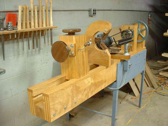
Another variation of a self-made machine
How to make a copy-milling machine with your own hands
Many home craftsmen would like to buy a copy-milling machine to equip their workshop, but the cost of such equipment is quite high. Meanwhile, having a desire, having spent not so much time, effort and financial resources, you can make such equipment with your own hands.
Naturally, home-made copy-milling equipment cannot be compared with professional equipment in terms of power, reliability and functionality, but even on such machines you can make high-quality copies, work with wood and process workpieces from other materials. Many are trying to fit a copier to an existing one, but this is not practical, since in this case almost the entire machine has to be redone. As practice shows, it is better to assemble your home-made copy-milling machine from scratch, choosing the appropriate components for this.
The photo below shows an example of a homemade machine with the addition of a video. The creator of the machine is narrating in English, but in principle everything is quite clear and without translation.

With your own hands, a copy-milling device is easiest to make according to a typical scheme, which includes a supporting structure - a frame, a desktop and a milling head. The drive for ensuring the rotation of the working tool is an electric motor that transmits movement through a two-stage mechanism that allows you to get two speeds. The desktop of this homemade device can be adjusted in height.
Many of those who made a copy-milling machine with their own hands note that when changing operating modes, such equipment begins to show a lot of shortcomings. The most common of these shortcomings are machine frame vibrations, workpiece distortion and deflection, poor copying performance, etc. To avoid such problems, it is best to make the copy-milling device highly specialized and immediately set it up for processing the same type of workpieces. This is explained by the fact that it is almost impossible to take into account all the shortcomings that universal equipment will have when changing operating modes.
Milling is a type of mechanical processing of materials using a special cutting tool - a milling cutter. The method allows to obtain a high quality of accuracy and the degree of roughness of the treated surface. In addition, it is distinguished by significant performance.
Surface treatment is carried out by up milling, when the rotation of the cutting tool is opposite to the direction of feed, and by climb milling, in which the direction of rotation of the cutter and feed are identical. Using milling cutters with cutting edges made of modern superhard materials, it is possible to replace the grinding operation.
Milling equipment is divided into universal and specialized. In the first case, these are general-purpose machines for performing longitudinal and continuous milling, with and without a tool mounted on a console. In the second - a mechanism for cutting threads, splines, making gears and keyways and milling on a copier.
In production, there is often a need to manufacture several pieces, a batch, or even a series of identical parts. For this, milling equipment equipped with a pantograph is used.
In the household, the functions of a milling machine are usually performed by a manual milling cutter. To perform the maximum list of works, the milling cutter is equipped with a whole set of devices. The main equipment is supplied with the equipment, additional equipment is purchased or manufactured independently. These are a variety of stops, clamps, templates. But you can go even further and make a copier for milling volumetric parts.
Milling and copying equipment: the principle of operation
The principle of operation of such a device is to clearly transmit the movements of the copy head through the holder profile to the cutting tool.
It is quite difficult to buy a copy milling machine, so craftsmen make it with their own hands from improvised materials. Everything happens by trial and error. Therefore, the craftsmen advise first to assemble the duplicarver, and only then to introduce it into mass production. As a rule, this stage is preceded by more than one serious fit and alteration.
Milling and copying equipment: areas of application
On milling copy machines, it is possible to process not only flat, but also volumetric parts. With their help, along with simple milling operations, you can engrave, repeat drawings, patterns and inscriptions. The design of the machine is quite simple, and any master can make it.
Copy-milling machines allow you to process not only wooden parts, but also cast iron, steel and plastic blanks, as well as non-ferrous metal products. This is ensured by high-quality tools made of high-speed steel and hard alloys. The copy machine allows you to mill not only straight, but also curved surfaces. In this case, the details are completely identical.
Milling and copying equipment: design
The typical design of a copy-milling machine is quite simple. It consists of a working table and a system of rails with clips for fastening the router and copier.
Making a universal copy-milling machine at home is quite difficult, and there is no great need for this. For home conditions, equipment with a narrowly focused specialization is usually created.

Making a copy-milling machine: materials
To create a duplicarver at home with your own hands, you should draw an elementary sketch, which will become a guide to further actions. In addition, you need to stock up on some materials. This:
- Knee cemented polished shaft Ø 16 mm.
- Linear bearings in the amount of 2 pcs.
- Rail guides 900 mm long - 2 pcs. For ease of fastening, their length is taken as a multiple of 150.
- Split linear bearings in the amount of 4 pcs. It is desirable to use bearings with a clamping screw to adjust the tightness of the fit on the guide.
- Profile pipe 30×60 with wall thickness up to 3 mm.
- Metal plate 900 long and 100 mm wide.
- End posts in the amount of 2 pcs.
- Movable element in the form of a plate - 1 pc.
- Rocker for attaching a copier and a router - 2 pcs. The length is chosen arbitrarily.
- Movable couplings - 2 pcs.
- Profile pipe 40×40 with wall thickness up to 3 mm.
- Crown clutch for turning workpiece and template.
Making a copy milling machine: tool
After that, you need to prepare a tool that will definitely come in handy for assembling the machine structure. This:
- angle grinder;
- cutting and cleaning disc;
- welding machine;
- welding mask;
- petal disk or brush;
- self-tapping screws for mounting rail guides and movable elements;
- electric drill;
- screwdriver;
- measuring instruments: tape measure, caliper;
- puncher and scriber.
Making a copy milling machine: step by step instructions
After everything is ready, the direct assembly of the copy-milling machine begins.
Step #1
It is necessary to cut two pieces 950 mm long from a profile pipe 30 × 60 for fastening rail guides. A margin of 50 mm is needed to install the limit switches in order to prevent the linear bearings from jumping off.
Step #2
The profile pipe 40 × 40 must be cut into blanks for the base. Guided by the existing sketch, you need to cut off two pieces of 1350 mm and two pieces of 900 mm.
Step #3
From the same pipe it is necessary to cut off small racks. Their linear size depends on the height of the subsequently processed parts.
Step #4
Now you need to remove rust from the pipes. To do this, you can use a petal disc or a brush.
Important! Before using the brush, pay attention to the maximum number of working revolutions on it and the grinder. The value of the speed on the brush must exceed the number of revolutions of the equipment.
Step #5
After that, we scald all the joints and clean the seams with a cleaning wheel 6 mm thick.
Step #6
Then it is necessary to achieve parallelism of rail guides. To do this, you need to make the connection of the rack and the base of the rail guide detachable. It is necessary to take a washer according to the internal size of the rack, weld a nut to it and screw in the bolt. The bolt at this stage is needed in order to install the nut with the washer in the cavity of the pipe-rack flush and in a strictly vertical position, and when welding it, do not damage the thread. You need to do this with all four racks.
Step #7
Racks welded to the base.
Step #8
Holes must be drilled at the base of the rail guide at the junction with the uprights: in the upper shelf for the bolt head, in the lower shelf for the thread.
Step #9
Install the rail guides on the base (pipe 30 × 60), having previously drilled holes, and fasten with metal screws.
Step #10
Mount bases with guide rails and tighten with bolts.
Step #11
Check the parallelism of the guides. If it is absent, it is necessary to make adjustment by placing foil of different thicknesses on the racks under the guide.
Step #12
On a metal plate, you need to mark and drill holes for mounting split linear bearings and end posts.
Step #13
After that, it is necessary to make a movable element by welding rocker arms 300 mm long for a probe and a milling cutter to a metal plate, then attach linear bearings to it.
Step #14
After that, the movable element must be put on a polished shaft, along the edges of which end posts should be installed.
Step #15
The entire structure must be installed on a metal plate 100 mm wide and fixed with self-tapping screws.
Step #16
Then split linear bearings must be installed on the metal plate from the bottom side.
Step #17
After that, the hinged structure is put on the rail guides with split bearings and the limit switches are installed.
Step #18
At the end of the rocker arms, movable couplings are installed and a probe and a milling cutter are attached.
Step #19
In order for the workpiece and the part to rotate synchronously, it is necessary to connect them with couplings. An asterisk and a crown are suitable for control. The copy-milling machine is ready. The design achieved 5 degrees of freedom. Movement along the X axis is ensured by the movement of the structure along the rail guides, movement along the Y axis - by the movement of the movable element along the polished shaft, movement along the Z axis - by the movement of the rocker arms.
Additionally, due to the movable couplings, the probe and the milling cutter can move left and right along the axis of the rocker, and there is the possibility of synchronous movement of the template and the workpiece. This makes it possible to process parts of almost any shape.
Copy-milling machines for metal in mass and serial production
Copy-milling machines for metal are used in mass production. With their help, propellers for ships, turbines of jet engines, pump impellers, dies for forging and pressing production, blanks for mechanical and foundry production are made. In everyday life, metal copiers are practically not used.
Pantograph for milling cutter: design features
To scale copy processes, there is a special device called a pantograph. It facilitates the manufacturing of parts with curved surfaces, allows you to make ornaments and patterns of any complexity in a reduced form. The cost of such a device is quite high. But making a pantograph at home with your own hands is quite realistic.
Pantograph for milling cutter: principle of operation
The schematic diagram of the pantograph looks quite simple. It is a square divided in half. All connections are hinged, so all sides are movable, and the square easily turns into a rhombus when impacted. The zero point, located in one of the corners of the square, is fixed rigidly. Relatively, its design can be modified, turning into a rhombus. A cutting tool is installed in the middle of the square. A copier is fixed diagonally in the opposite corner of the square. The distance from the zero point to the cutter is a certain value A, and to the copier 2A. This gives a scale of 2:1. The linear size of the long and short sides of the pantograph should also differ from each other by 2 times.
Pantograph for milling cutter: materials
In order to make a pantograph with your own hands, you will need the following materials:
- Square metal profile 12×12
- Bearing 180201.
- Bushings for the outer race of the bearing.
- Fingers on the internal size of the bearing and thread M12.
- Nut M12.
- Bolts М6×45
- Nuts M6.
- Bushing for fixing the copier.
- Profile pipe 40×40
- Metal-plastic window hinge.
- Dye.
- Masking tape.
- Metal plate.
- Screw for fixing the copier.
Pantograph for router: tool
In addition to the listed materials, you need a tool:
- Manual frezer.
- Angle grinder.
- Welding machine.
- Spanners.
- Measuring tool.
Pantograph for a milling cutter: step-by-step instructions for making your own hands
We proceed to the direct manufacture of the pantograph.
Stage number 1. cutting blanks
It is necessary to mark and cut a square profile according to the calculated dimensions. For convenience, you can use masking tape and a metal plate. Scotch tape will enable clear marking, and the plate will help to make an even and high-quality cut. The blanks for the site for the milling cutter must be cut at a right angle, and on the sections of the profile for the connecting rods, make a bevel for maximum fit of the bearing sleeve.
Stage number 2. Drilling process holes
On all blanks, it is necessary to chamfer and drill holes Ø 6.2 mm for further connection into the structure.
Stage number 3. Welding a platform for a milling cutter
After that, you need to weld the platform under the milling cutter.
Stage number 4. Making connecting rods
On the board, it is necessary to make a semblance of a conductor and rigidly fix all the parts to be welded. To do this, a hole is drilled in the board, and the bearing in the sleeve is clamped with a bolt, the square profiles of the connecting rods are fastened with clamps. Beforehand, two washers must be inserted between them and fastened with bolts. After that, all joints of the structure are scalded and cleaned. Then you need to cut the bearing bush between the square profiles on each connecting rod. M6 bolts, washers and bearings must be removed. A mount for the router must be welded onto the frame, and an extension for scaling must be welded onto the short connecting rod at the point opposite to zero. The cranks can be painted to give an aesthetic look.
Stage number 5. Making a node for attaching a copier
Now you need to machine two bushings with an inner diameter similar to the size of the copier. On the side, drill a hole and cut a thread to install the screw that fixes the copier. After that, you need to cut off two pieces of a 12 × 12 square 20–30 mm long and weld them on the side between the bushings. The size between the squares should be 12 mm.
Stage number 6. Manufacture of the bearing lifting mechanism
It is necessary to make a bearing lifting unit. To do this, the zero point finger must be welded onto a piece of a 12 × 12 profile and fixed to a 40 × 40 profile pipe using a hinge from a metal-plastic window. The profile pipe will serve as a place for attaching the pantograph to the table with a clamp.
Stage number 7. Pantograph Assembly
The bearings must be installed in the bushings and securely fastened by tightening the square profiles of the connecting rods with M6 bolts. With the help of fingers, it is necessary to assemble the connecting rods into a single structure. Fix the pantograph on the table with a clamp and install the router. The device is ready to work.
Cutting tool for milling work: copy cutters
Copy cutters are a tool on which, in addition to the cutting part, there is a bearing. Its size is equal to the diameter of the cutting part of the cutter. The bearing can be located both in the upper and lower part of the cutter. This is how the tool is classified. It is worth considering that the marking means the position of the bearing with the usual placement of the cutter - shank up.
They serve to perform copy work on a template. When using a cutter with an upper bearing, the template is located on top of the part, if with a lower bearing position, then from below.
Work with a manual milling cutter involves the use of any cutters. It is safe. The only thing is that when using a cutting tool with a top bearing, you should pay attention to the overhang of the cutter so as not to damage the workbench.
Milling on a woodworking machine involves the use of cutters with only the lower position of the bearing. This is due to the fact that in a cutter with an upper bearing position, the open rotating cutting part is in the area of the workpiece. Careless movement can result in serious injury. Such cutters are used on machines only in special cases with maximum compliance with safety regulations.
Copy-milling machines are unique equipment with the help of which the most complex work on the manufacture of identical parts is carried out. But for work at home, you can make simple analogues of such equipment and devices that will help in everyday life or a small business.
A copy-milling machine is used to create copies of products made of wood or other material of a certain shape. Such machines are used in large and small industrial enterprises, as well as at home to create various parts. Next, we describe the principle of operation of such a machine and give recommendations on how to make it yourself.
1
Milling equipment with a copy machine is used for machining various planes. With the help of a high-quality machine, you can reproduce copies of three-dimensional forms, engrave, make patterns, drawings. Its main feature is the simplicity of design, while it can perform a rather complex list of works.
Copy-milling machine
Such equipment has a simple principle of operation. A special copy probe is connected to the working plane. Then he mechanically creates contours from a template or part. On the working plane, a cutter is mounted under wood or metal, depending on the purpose of the machine, which repeats the movements of the copy probe. In addition to these parts, the standard machine is also equipped with a cutter clamp or milling unit, an electric motor and a guide system. Typically, equipment for simple wood or plastic work consists of three main elements:
- work surface with a supporting element and a frame;
- cutter or milling machine with a clamping mechanism;
- copier (pantograph) and copy probe.
Depending on the type of copy-milling machine, it can work in two or three dimensions. To create a simple template in two dimensions, the standard version with a clamping profile is sufficient, but for the production and drilling of three-dimensional holes, the machine must be equipped with a pneumatic clamping unit, a drill and a drill or other drilling unit. Depending on the configuration and capabilities, it can work not only with wood, but also with plastic, cast iron and other non-ferrous metals. To do this, the machine is equipped with powerful and durable cutters for various materials, and copying equipment is being improved for certain shapes.
Do-it-yourself machines are often used in the household for drilling lock holes, making frames, or creating grooves in wood or metal parts.
2
To date, there is a large number of copy-milling equipment of various designs with certain features of work. Their cost is usually quite high, so many amateurs make such devices with their own hands. A home-made version, of course, will differ from industrial counterparts, however, subject to certain conditions, it will do an excellent job with its functions.

Copy-milling machine made by yourself
The standard scheme of a home-made machine consists of a working surface, a supporting structure and a milling head, which is equipped with an electric motor with a drive to enable the head to work at two speeds. Thus, to do the installation yourself, you will need a set of certain equipment and tools, namely:
- main frame made of wood or metal;
- wood plywood or panel, bars, boards and slats;
- fasteners in the form of bolts, nuts, screws or nails;
- milling machine;
- a set of keys, saws or a hacksaw for working with details;
- guide system and metal pipes;
- electric motor with drive or manual drive;
- drills and drilling installation (for more complex options).
Instead of a wooden or metal frame, you can use a ready-made milling machine as a base, but attaching a copy device to it is much more difficult than making a machine from scratch. In this case, you will have to almost completely redo the milling machine, and this will require more time and additional equipment.
3
The basis for making a machine with your own hands will be manual. Fix it on a wooden support made of thick plywood (at least 12 mm thick). Several holes are also made in the support for fasteners and a router holder. Additionally, a frame should be built and several bars should be made, which are installed along the edges of the support, they will hold the apparatus during operation.

Production of a milling plant
As a guide, we use a metal pipe of medium diameter. We install a carriage with a milling cutter inserted into it on the pipe. We attach a bar to the carriage, which plays the role of a copy probe, after which it is necessary to fix the horizontal bar on which the main template is attached. A machine made according to this principle can be used to process and create copies from simple household items, such as door handles, locks, furniture legs. The milling unit with a motor is inserted inside the carriage and connected to the power supply. A template is fixed on the support, a copy probe moves along it.
The milling cutter is powered by a network, the carriage moves manually, so that the working head repeats the movements of the probe. To create more complex models, it is necessary to connect additional working heads and install a drive with a belt drive. Now it is possible to connect a home-made installation to the software, but this will require a CNC and additional equipment and tools. Such a home-made machine will cope with its household functions quite well.
4
The practice of using home-made copy-milling machines of various types shows that the final part made on such equipment has certain inconsistencies with the drawings and shapes and some manufacturing defects in the form of chips and distortions. These flaws are due to the constant vibrations of the machine and the movement of the working head. It is very difficult to get rid of them at home.

DIY copy-milling machine
To avoid such shortcomings in the operation of home-made equipment, we recommend making highly specialized machines, rather than universal-type equipment. That is, before starting work on the manufacture of the machine with your own hands, you need to decide for which specific parts it is planned to use it. So you can optimally select the weight and dimensions of the hand-assembled copy-milling machine. It is important to remember that the larger the size of the parts to be machined, the more powerful and heavier the working rig must be.
For large parts, additional holders and a more massive support are needed, this will allow you to dampen the vibrations that will occur during operation as much as possible. In addition, it is better to use an electric drive instead of a manual one and make sure that the guides have a sufficient margin of safety. Remember that the smoothness of movement of the cutting equipment in various planes depends on the type of work surface, and therefore the final result.
Copy-milling machine "Duplicarver" is used for copying sculptures and flat-relief products, as well as woodcarving. To date, there are no analogues of such equipment on the Russian market. The equipment has received recognition among specialists and beginners. This device complies with the requirements of the technical regulation.
On sale you can find three types of machines:
- "Duplicarver-1";
- "Duplicarver-2";
- "Duplicarver-3".
With their help, it is possible to carry out not only cultural and volumetric carving, but also flat-relief work. It can be a panel, as well as panels of small depth. The dimensions of the products are determined by the width, and their length can be any. Duplicarver-3 retained all the characteristics of Duplicarver-2 and acquired new ones. With it, you can carry out long volumetric threads.
The high-quality milling cutter, which is made in Germany, acts as a working tool of the device. The machine works accurately and as reliably as possible, and you can master the techniques of working on it quickly enough. If you can’t afford such equipment, then copy-milling machines for wood can be made independently. For this, there is no need to buy any complicated spare parts.
Classification by degree of automation
When copy-milling machines for wood are made, initially the craftsmen deal with varieties of such equipment, it can be
- desktop or manual;
- automatic;
- stationary.
In the first case, the workpiece is fixed mechanically; holes of various shapes are usually drilled on these devices, however, the template affects the parameters. Stationary automatic equipment fixes the workpieces with the help of pneumatic clamps, it is possible to work on it with aluminum.
When preparing the drawings of a milling and copying machine before its manufacture, you must also understand that there is stationary automatic equipment with pneumatic clamps, which are complemented by three-spindle heads.

Homemade equipment can be created from a blueprint. As a result, it will be possible to get a device that performs its tasks, like factory equipment. The copier will consist of such nodes as:
- working surface;
- device for installing a milling cutter;
- carrier frame.
When they are made with a milling head, it should be supplemented with a transmission mechanism and an electric motor, only in this way can several speeds be obtained. As a result of using such a unit, it is possible to complete a part that may have a certain number of flaws.
They can occur in the process of changing the direction of the cutter, vibration and jitter of the structure. A discrepancy can also appear due to the curvature of the part, this problem occurs with internal stress. You can eliminate shortcomings by making a machine for making parts of a certain type.
Features of creating a copier

If you decide to make a copy-milling machine with your own hands, then it should be optimized for processing specific parts. An important factor to consider when making your own machine is the total weight. This should also include the dimensions of the structure.
It should be more massive if you plan to process large items. This allows the equipment to reduce the vibrations that occur during the operation of the cutter. With a significant margin of power, guide axles should be made, only then they will not sag under increased loads.

When a copy-milling machine is made with your own hands, it is important to understand its design features. The system will have a working head and a supporting frame. The working surface can be adjusted in height, while the milling head must be supplemented with a two-stage transmission mechanism that provides two shaft speeds.
Making a pantograph
Copy-milling machines for wood have a pantograph as the main unit, which can be made from wood. However, one should be prepared for the fact that in this case it will not be possible to achieve high accuracy, because the connection of wooden blanks is carried out using loops.
If you use loops to fix them, then a backlash will form between them. Metal is also sometimes used to make a drawing pantograph, with its help it will be possible to create copies at different scales, but it can only be used to create three-dimensional copies.
Work methodology

It is possible to connect the working body with each other by pneumatic, hydraulic or mechanical elements, which are required to form the force from the copier to the working body. A flat contour or spatial model can act as a template. You can use contour drawings, a reference part, but a copy roller or finger, photocells or a probe will become an element for reading sizes and shapes.
You can use wood, plastic or metal for the template. It is necessary to place this node on the rotating desktop of the equipment. When CNC milling and copying machines are manufactured, they must have a working body that starts moving thanks to a solenoid, a spool valve, or relays are located in the amplifying devices, they can be hydraulic, electromagnetic or electro-optical.
Features of the manufacture of copy-milling turning equipment
The copier will work, providing quality that depends on the speed of movement of the tracking device. The executive chain will have a main element in the form of a hydraulic cylinder or an electric motor. The guide pin will make up the pantograph design. It is necessary to place the guide pin and the spindle on the same rail.
The rail must have shoulders, the ratio of which will determine the scale of copying. The copier will have a finger that will move along the contour of the templates. He will be responsible for the movement of the rail, which rotates freely on the axis. On the other side of the rail, the spindle will make identical movements when processing parts. On such machines, the described device will not be superfluous, and its presence will increase functionality.
Conclusion
Copy-milling machines have gained great popularity among consumers today for the reason that in everyday life and in production it often becomes necessary to create copies or repeat products. To do this, today devices are used that provide high performance and accuracy, which cannot be achieved manually.


