Later, the Radiotehnika S-30B Сг3.843.055ТУ-86 and Radiotehnika S-30A ИШch3.843.060ТУ-87 (OGK plant) were developed. They use dynamic loudspeaker heads 25GDN-1-8-80 (25GDN-1-4-80 in S-30A) and 6GDV-1-16 (same speakers, designation according to OST4.383.001-85).
For work AC must be connected to an amplifier that has a maximum output power of 20...50 W at the output of each channel. The speakers S-30 and S-30B have an overload indication of the loudspeaker heads, which is triggered when a signal is supplied to them with a level exceeding the rated power of the speaker. If the OVERLOAD indicator starts to glow for a long time during operation of the speaker, you should reduce the level of the signal supplied to it.
Main technical characteristics:
Rated electrical power - 10 W.
The rated electrical power is at least 30 W.
Nominal electrical resistance S-30 - 4 Ohms, S-30A - 4 Ohms, S-30B - 8 Ohms.
The range of reproduced frequencies is no longer 50...18000 Hz.
Nominal average sound pressure in the range 100...4000 Hz for S-30 - 1.2 Pa.
Characteristic sensitivity in the range of 100...8000 Hz, at a power of 1 W, for S-30B no less than 84 dB.
Overall dimensions of the speakers: 364 - 214 - 195 mm, weight no more than 6 kg.

Electrical circuit diagram of acoustic systems Radiotehnika S-30 (10AC-221 - 10AC - 222)
Audio equipment
Speakers Radiotehnika S30 characteristics
The development of acoustic systems does not stand still, but this does not mean that the equipment produced in the last century is no good.
On the one hand, there are connoisseurs of high-quality equipment, on the other, the mechanics of the sound reproduction process have not advanced much over the years. In addition, widespread savings on components often result in poor quality of final products.
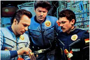
Thus, the Radiotekhnika S30 speakers, manufactured in accordance with GOST 23262-76 (current edition of 1988), at the REMZ plant (Riga Electromechanical Plant) back in 1983 can be used in everyday life today.
What is called, “Made in the USSR”.

Rice. 1. Speakers Radiotekhnika S30
Characteristics
- The maximum power according to the product data sheet is 30 W.
- Nominal - about 10 W.
- Peak – up to 300 W.
- The range of reproduced frequencies is from 50 Hz to 18 kHz.
- Working – 50-16000 Hz.
- The weight of one column is 6 kg.
- Dimensions (height/width/depth) - 364x214x195 mm.
- Nom. resistance – 4 Ohms.
- Minimum impedance – 3.2 Ohm
- Average sound. pressure – 1.2 Pa.
- Sensitivity – about 84 dB.
- Speaker for low and medium frequencies - 25 GDN-1-4 (equivalent to 10 GD-34).
- Speaker for high frequencies - 6 GDV-1-16 (equivalent to 3 GD-2).
- Filter separation frequency (into two ranges, 1 – LF+MF, 2 – HF) – 5 ±0.5 kHz.
- Harmonic distortion (total coefficient) – 1-2%.
- The frequency response looks like this.

Rice. 2. Frequency response of speakers
Description
The equipment was equipped with a first-order filter for high frequencies (the main speaker for low and medium frequencies was connected without a filter) with a frequency of 5 kHz.
Structurally, the body was a box with walls made of chipboard, trimmed with veneer (imitation of several variants of expensive wood species was offered).
The front panel contains both speakers, a bass reflex (in the lower part of the body, diameter 30 mm), an overload indicator and a nameplate with the frequency response.
The rear panel contains connection terminals (screws) and a fastening element for wall mounting.
The plant produced several modifications of these speakers:
- S30A,
- S30B.
They differed slightly in appearance and frequency response graph.
HF filter circuit
The characteristics of the S30 turned out to be so good that the speakers remain in demand among music lovers to this day.
In case of repair of a failed filtration unit, we have attached a schematic diagram.

Rice. 3. Schematic diagram of acoustic systems S-30
Publication date: 20.03.2018
Readers' opinions
- Rinat / 05/15/2019 - 10:29
2 Master Sound: if without bass reflexes, this is the S30A option. 2 Seabreeze: look for “filter for s30 fagear” - this is an updated board using the same circuit, you can install modern, more compact components (except for the coil - it’s better to use the original one). But this is an option for do-it-yourself soldering. - Ruslan / 05/07/2019 - 12:58
Can you tell me how much I can buy it for? - Seabreeze / 04/14/2019 - 10:59
What is a more compact replacement for the high-pass filter? Can anyone recommend something from Ali Express? - Master Sound / 04/10/2019 - 00:04
I bought these speakers for only 1350 rubles. They sound great. They look the same. Only there are no phase inverters and an overload signal, and instead of a filter board there is a condenser and a resistor. Despite this, the sound is excellent. Moreover, my amplifier is my own Radiotekhnika U 101, but already modernized. All capacitors were replaced with similar imported ones. volume, timbre and balance resistors were replaced with new ones and the stereo unit was turned off, which does not distribute the signal into channels, but mixes them with each other. I use these speakers as near-field studio monitors and perfectly mix soundtracks even for famous Russian pop artists. P.S. Well, if you want to KILL the sound, then buy Chinese plastic active monitors from YAMAHA or Sound King. This is a 200% proven kill :-)
I am a big fan of Soviet acoustics, amplifiers and generally everything related to sound. The background to this article is this: one day I saw a Raiotehnika S-30 speaker in a friend’s garage. True - one. The second one was somewhere in his car at work. I took the first column right away. The second one was brought to me a couple of weeks later. The first column was in more or less normal condition. The one that rode in the car was much worse: a scratched and battered body, bent protective nets, a scratched front panel. Immediately after I had the speakers at home, I decided to modify them.
Main technical characteristics:
Rated electrical power of at least 30 W
Rated electrical power 10 W
Nominal electrical resistance 4 ohms
Nominal average sound pressure in the frequency range from 100 to 4000 Hz 1.2 Pa
The range of reproduced frequencies is no longer 50-18000 Hz
Overall dimensions of speakers 364x214x195 mm
The weight of the speaker is no more than 6 kg.
Later, the following stages of working with acoustics were determined:
- Final assembly of the speakers.
Complete disassembly of the speakers.
Improved appearance.
Sound improvement.
The first thing I did was completely disassemble the speakers: I removed the front panel with the grilles, removed the speakers, bass reflex, filter, and pulled out the sound absorber. Only empty buildings remained.


Next, remove all the sealant, which has probably already dried from time to time. After this, we glue the housing in the middle along the seams with PVA wood glue or silicone sealant. As a last resort, you can use regular stationery PVA glue.

This is the longest procedure, since it takes about a day to dry one seam. After we glue all the seams inside, carefully sand the outside of the housings for further putty.

After sanding, we wipe the speaker housings from dust and putty all the defects. I used acrylic wood putty.


It is better to putty the columns several times to improve their appearance. But this depends on the condition of the buildings themselves. After puttying, do not forget to sand the bodies again with fine-grained sandpaper.
We cover the inside of the case with padding polyester or felt. If there is neither one nor the other, we use ordinary foam rubber. The sound absorber improves the sound quality of the acoustics.
After this, we cover the speaker housings with self-adhesive film. We select the color according to our taste. I chose the film as dark as possible, but when I brought it home, I saw that it was much lighter than I wanted. But it's not scary. I took a film 45 cm wide. By cutting it into two parts lengthwise, you can paste over two buildings at once. The width of the film is enough for wrapping on the front and back of the column.


We carefully sand the protective grilles, otherwise the paint will not adhere well and will peel off over time. We do not sand the front panels so as not to spoil their texture. I covered the nameplates with the frequency response with masking tape so as not to paint them over. It is better to paint in 2-3 layers.


Now let's move on to speakers and filters. We replace the wires in the filters with acoustic ones. I took a speaker cable with a cross section of 1.5 mm 2 . But for such speakers, a cable with a cross-section of 1 mm is quite enough. 2 . If there is no speaker cable, you can use a regular copper cable with PVC insulation. We throw out the terminals on the filter board for connecting the speakers! We solder all the wires to the board! Some craftsmen, when working with filters, remove the overload indicator, as it degrades the sound quality. But this is a purely subjective opinion. Personally, I didn’t notice a difference, I just turned the sensitivity to maximum and installed green 5 mm LEDs. It turned out a la “color music”. LEDs blink in time with low frequencies. The overload indicator electrolytes passed capacity tests, so I did not replace them. I replaced the standard terminals with acoustic ones.


We paint the low-frequency speakers with office ink.


My phase converters (FI) were completely dry and crumbled. So I bought a sewer pipe with a diameter of 32 mm. It fits FI size perfectly. We cut two pieces of pipe and glue them to the front panel with super glue. To cover the large hole in the speaker housing, I used a piece of old FI.


After all the operations have been completed, we begin assembling the speakers. Apply sealant in the areas around the speakers. I used the first one that came to hand - black silicone sealant.

We put the speakers in place and solder the wires to them.

If desired, we put grilles on the speakers. You don’t have to install them, but I have curious individuals who like to rub their hands on the vibrating speaker :)


We put the front panels in place and fasten them with new screws. To prevent them from standing out too much, I painted the screw heads with the same paint as the front panels.

As a result, this is what I got.


They play from the Radiotehnika U-7111 amplifier along with the Radiotehnika S-50B acoustics. I connected the speakers with the same speaker cable as in the filters. I like the fact that the amplifier allows you to connect two pairs of speakers.

OK it's all over Now. I look forward to your criticism, advice, and suggestions. Sincerely, resident of the "Soldering Iron" forum -
Appearance of the S-30
The main advantage of the S-30 is its very correct tonal balance (IMHO). The 4 ohm versions of the S-30 were redesigned. Or rather, the speakers were reassembled - there were 6 cases and 4 filters, the speakers were selected from old, but little used 6AS-2, 1979-1983.
The sound has improved - this was expressed in a noticeably more solid bass and, coupled with the anti-magnet on the 10GD34 and “raised” high frequencies - in a certain, I would say, fundamentality of the resulting sound.
The main advantage of the S-30 is its very correct tonal balance (IMHO)
The 4 ohm versions of the S-30 were redesigned. Or rather, the speakers were reassembled - there were 6 cases and 4 filters, the speakers were selected from old, but little used 6AS-2, 1979-1983. All three pairs of HF heads are fabric, with a very low resonant frequency for 3GD-2 - a pair with Fs = 3100-3200 Hz, a pair with Fs = 3350-3400 Hz and in the last pair Fs = 3800-3950 Hz. 10GD34 with Fres = pair with 56 Hz and 2 pairs with 70 Hz.
Original S-30 diagram
In one pair of speakers, instead of a block of factory inductors, I made a similar one of my own - using a low-frequency coil with a thicker wire: f1.3, observing approximately the same design of the triple coil, location on the “trough”. I glued the high-frequency coil through a 10-mm spacer onto the low-frequency coil so that it would be like in the original filter, I adjusted the low-frequency coil to the original filter (LLF = 0.394..0.398 mH before the tap and LLF = 0.48 mH with the tap (from the tap is approximately 12...14 turns), LHF = 0.28...0.297 mH, f0.72mm - these are the measurements that gave me four “original” filters from 1983). True, my winding diameter and length were larger - 35mm and 40mm at HF and LF.
I made the board myself, of course, without an indication, and placed it on a removable cover, just like in the original board. But due to the increased size of the coils, they are located closer to the woofer. There were doubts that this would greatly disrupt the setting. The capacitances were: in the low-frequency notch: 1.98-1.99 µF; R-C chain at LF: 7.3 ohm + 8.0 µF; on the HF I used paired MBMs: input - 1.98 µF and 2.09 µF - this is for the speaker). If you have a good inductance meter and winding wire, this is not difficult. Inductances and capacitances in pairs are similar with an accuracy of 1-2%.
Scheme of S-30 after conversion
The main directions of improvement of the S-30
S-30 has no bass
This is true, but you can improve the sound by choosing a 10GD34 - with fs<70 Гц, и оклеив стенки войлоком, подобрать длину ФИ - при рассыпающися ФИ из пенорезины "умощнить" ФИ внутренней пластмассовой вставкой внутренним диаметром 30мм - хорошо подходят баночки из контейнеров для любой фотоплёнки- обрезаешь донышко - и готовый каркас/удлиннитель для ФИ.) Войлок 10-15мм, наклеиваемый на все внутренние стенки, кроме передней, значительно улучшает звук -после этого мидбас не хрипит даже при 30вт мощности, но можно сжечь динамики.
High ones - "pour"
It can be improved by installing older HF 3GD-2 with silk domes (1979-1983) and selecting a notch parallel to the HF 3GD2 - with frez = fres HF, for example: C-L-R: L = 0.4 mH, C = 6.5 mk, R=6.8 Om for fres HF = 3121 Hz, as well as using other types of HF capacitors - namely MBM, 2x1.0 µF x 160 V. It is not advisable to increase the capacitance in the notch to more than 6.5 microfarads - it is better to play with inductance to adjust the circuit. You may have to adjust the division coefficient in the resistive divider at the HF (in the “native” HF filter, the trimmer sliders are in the middle: 33 ohms / per 2 = 16 ohms, i.e. the HF signal was divided approximately in half).
MBM capacitors produce a very bright sound, although we must remember their limited variable capabilities (160V x 5% = ~8V). The notch almost eliminates the hissing and tutting at the HF resonant frequency, but limiting it with a 6.8 ohm resistor is necessary so that the desired after-sound of strings and cymbals remains. The capacitor in the notch is K73-17, inductance L=0.31..0.45 mH is wound with PEL-1 wire f 0.72mm. Resistor 6.8 ohm - precise, +/- 1%, 2 watts, type C2-13.
Result of measuring filter inductances
The middle is a bit cloudy
Yes, it's hard to get rid of!Recoil and resolution are low
Yes it is. But, you can experiment carefully: add a countermagnet of the required size to the 10GD34 and use a trimmer to reduce the coefficient of the resistive divider at HF, having previously noted the initial position of the trimmer so that you can return to the original state of the filters. All this will increase the mid-high frequency output and the overall dynamic range. The anti-magnets in one pair are glued slightly different - I selected them to equalize the output of both speakers in the midrange.
High distortion level
Yes, there is such a thing, and it’s unlikely to be cured. I tried to cover the front panel from the inside with plasticine - the sound disappeared - I had to return everything back!
Summary
The sound has improved - this was expressed in a noticeably more solid bass and, coupled with the anti-magnet on the 10GD34 and “raised” high frequencies - in a certain, I would say, fundamentality of the resulting sound. This is not only my personal opinion, but also that of everyone who listened to both versions of the filter (on the same speakers with speakers), including my wife - the most unbiased listener (oh, these wives of ours - how they don’t like our hobby, tearing off, their words, us from them!). The factory filter sounded collected, correct, but somehow “near” the speakers. The homemade sound came out of the speakers and was above the speakers, EVERYWHERE.
Nuances
The use of MBM on HF gives a much more interesting sound than MBGO, but you need to take it before 1991, and, better, Moscow MBM 1.0 µF x 160V - Azerbaijani - are bad.
The homemade filter does not have a resistive divider after LHF - a tap to the 2.09 µF capacity of the low-frequency rejector and speaker; further - 132 ohms to ground, parallel to LHF. Selected from MLT-2.
The wires inside went to the HF - from SVEN and to the LF - acoustic - 1.0 mm2, with a blue inscription from YOTA. As it turned out, the wires sounded very good.
Oddly enough, this filter option produced a better sound than the original S-30 filter. Below is the result of measuring the filter inductances. The measurements were carried out with a digital L-meter adjusted for reference inductances that I have had for about 20 years.
According to my measurements, the real inductance is less than that indicated in the diagram, this is explained by the fact that in a real speaker it reaches the circuit one due to the relationship between the coils and the proximity to the woofer magnet.
Reader vote

The article was approved by 39 readers.
To participate in the voting, register and log in to the site with your username and password.I somehow got Soviet S-30 speakers. Their condition was deplorable: their speakers did not work (the wiring had broken due to age). Later I made them, temporarily hooking them up with small wires.
They worked for me for 2-3 weeks as part of the house. cinema, and one fine day I was inspired to remake them (“modding”).
Main technical characteristics of Radio Engineering S30:
What we need:
Soldering iron, straight arms, rosin, solder, glue, black “screws”, wires, a lot of free time, a car (bike) inner tube, a plastic pipe, that’s all.
First, let's take everything completely apart: 

First I changed the wires from the filter to the speakers:
BEFORE (agree, these wires are worse): 
After (sounding better with them):

Have you laid the wires? Now you need to glue the speaker body with any glue so that there are no gaps, I used “silicone”.
I placed the camera on the viscous mass (cut out the appropriate dimensions) and pressed it down firmly (this way the camera will “stick” to the speaker body)


Now it's time for the filters, I changed the wires on them.
Before: 
under development:


A few words about the filter:
If we want: we turn off the overload indication unit (if the amplifier is not more powerful than 25-30 W - otherwise then we listen with caution) - according to the diagram, we cut the track from the input (red wire +) to VD KA522B (see diagram) and unsolder the capacitor C2 10 μF and the transistor VT2 KT315b .
We disconnect the plug connector and solder the wires going to the speakers, throw away the old ones! In their place we put audio wires with a cross-section of at least 2.5 mm 2, directly to the board, on the back side of the connector. From the woofer speaker “+” to connector No. 2 and “-” to connector No. 3. “Tweeter” (HF), respectively, “+” to No. 5 and “-” to No. 2 (this is necessary - it is in antiphase).

Here is the filter diagram.
If you disable some elements (that you do not need) 
You can experiment carefully: add anti-magnets of the required size to the 10GD34 and reduce the coefficient of the resistive divider on the HF using a substring resistor, having previously marked the original position with a subtracting resistor so that you can return to the original state of the filters. All this will increase the mid-high frequency output and the overall dynamic range. The anti-magnets in one pair are glued slightly different - I selected them to equalize the output of both speakers in the midrange.