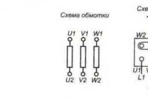
One of the stages of electrical installation work is the connection of wires in junction boxes, which follows immediately after laying the cables. According to the Electrical Installation Rules (ELR), electrical connections of wires must be made only in junction boxes.
Today, there are many ways to connect wires in a junction box. The choice of connection type depends on the following factors: core material - copper, steel or aluminum; working conditions - on the street or in an apartment; number of conductors - two, three, four; the cross-section of the cores is the same or different. Based on these factors, the most suitable and correct method is selected.
Why do you need a junction box?
Quite often there is some neglect of the distribution box (junction box). Some people think that using it when laying wires is a waste of time. After all, it still needs to be fixed to the surface, and this is additional effort. It is much easier, for example, to twist the conductors, insulate the junction and “roll up” everything with plaster.
- But this overlooks some issues:
- During operation, free access to the wire connections must be provided. For example, if there is no light in some room or the socket does not work? The test showed that the reason was the lack of voltage. How to find a distribution box in an apartment or a faulty section of the circuit? Tearing off wallpaper, breaking plaster to gain access to twisted wires?
- If in the future you need, for example, to install an additional one (two, three). Connect them “in parallel” from the first? Is this always convenient? While connecting new wires in the distribution box will not be difficult;
- Proper connection of wires is using terminal connectors. How deep do you need to drill a “channel” in the wall in order to hide the terminal block there?
- In terms of fire safety, the advantage of such a box is undeniable.
Wire connection methods
Special Electrical Installation Rules (PEU) regulate the correct connection of electrical conductors by welding, soldering, crimping or using screw and bolt clamps.
The rules do not stipulate the most common connection method - twisting. Although a properly performed twist is more reliable than a poor solder connection.
- The choice of connection method depends on several factors:
- materials to be joined. It can be aluminum, copper or a combination of both;
- number of cores in the connection. You can connect not only two, but also three, four or more wires;
- cross-section and number of cores.
Twisting wires
To make such a connection, you need to strip the ends of the wires, carefully twist them with pliers and insulate the twisted area. Very simple and without material costs. But such a connection weakens over time due to residual elastic deformation of the material, which means that the resistance in the connection increases and the contact begins to heat up to the point of destruction and fire.

Therefore, in no case should you lay twisted wiring on flammable substrates, for example, in a wooden house. And one more prohibition - poor protection against moisture does not allow such a connection to be made in rooms with high humidity. In this way, it is strictly forbidden to connect dissimilar materials, multi-core cables with single-core cables and at a current of more than 3 A.
In order for the twist to be of high quality, you need to remove up to 80 mm of insulation from the wires, fold them perpendicular to each other if there are two of them, and parallel if there are three or more, and twist them tightly. The remaining ends of the wires must be removed with pliers in a screw motion, as if smearing the material of the wires into one another.
The total length of the finished twist should be at least ten, and preferably fifteen, diameters of the cores. If special caps or heat-shrinkable tube (cambric) are used for insulation, they are put on the wire before twisting.
It is recommended to put on the heat shrink tube twice, and lay the insulating tape in at least three layers. Whatever insulating material is chosen, it must also capture the wires’ own insulation to protect it from moisture and slippage.
Soldering wires

This method is the best in terms of its combination of manufacturability and reliability, but requires some skills to make a quality connection. Before soldering, the wires must be thoroughly cleaned of insulation and oxides, tinned if necessary and twisted not as tightly as with simple twisting, coated with flux and soldered.
By soldering you can connect both copper and, with some skill, aluminum wires, with suitable flux and solder. Do not use active acid flux, as it will destroy the connection by remaining on the exposed wires. The connection point is isolated in the usual way. The distribution box in this case is called a junction box
- Despite the undeniable advantages, this method also has quite significant disadvantages:
- the need for skills in work, the complexity of the process;
- use of a special tool;
- permanent connection, that is, for repair it must be completely removed;
- an increase in resistance in the connection over time, which deteriorates electrical conductivity and increases voltage losses in the network.
Welding wires
Welding is an even more reliable connection method than soldering, but it requires a welding machine with personal protective equipment and welding skills, which is much less common in everyday life. Unless you need to carry out electrical installation work in a country house yourself, then purchasing an inverter-type welding machine will be economically justified.

Welding inverters are small-sized, have a wide range of welding current control, and provide stable arc burning with low power consumption. To weld copper wires, carbon-copper electrodes or carbon rods from ordinary AA batteries are used.
Preparation for welding differs only in the density of the twist and the fact that the free ends of the two wires, even if there are more of them in the connection, are straightened and pressed parallel to each other to facilitate the formation of a melt ball. Then the twist is placed in a welding clamp (regular old pliers) and the ends of the wire are welded with a carbon electrode to the main twist for two to three seconds so that the insulation does not melt. After cooling, the welding site is isolated in the usual way.
There is often a temptation not to wait for natural cooling, but to use cold water to speed up the wiring installation process. But cold water causes microcracks to appear in the material, which naturally affects the quality of the connection.
Wire crimping

This method of connecting electrical wires uses special tubular sleeves or lugs. The industry produces sleeves for wires with a cross-section from 2.5 to 240 mm², and it is very important to choose the right one for electrical wires specifically for each connection.
To perform the work you need a special tool. This may be a crimping press or tongs, mechanical, electrical or hydraulic. Having selected a suitable sleeve and adjusted the tool, remove the insulation from the wires, strip the ends and apply quartz-vaseline paste to them, put on the connector and crimp.
If the tool is simple, then you need to perform several compressions at some distance from each other. Using a good tool, you can crimp the sleeve in one go. At the end, the usual insulation of the joint is performed.
The wires to be connected can be inserted into the connector from opposite sides so that their joint is approximately in the middle of the sleeve. It can be convenient to insert both wires on one side, and the total cross-sectional area of all wires should be less than the cross-section of the sleeve. High-quality installation and reliable insulation are the positive aspects of using crimping.
- But there are also negative points:
- the sleeve is deformed during crimping and its reuse is impossible;
- the need for a special tool for crimping the sleeve, adjusting it to length and removing insulation from the conductor;
- to crimp the connection of copper and aluminum wires, you need a rather rare special sleeve;
- Quite a lot of time is spent on installing electrical wiring.
Using clips (PPE)
The clamp is a cap with a square steel wire coiled into a spiral cone. For aluminum wires, the cone is filled with a special paste that prevents oxidation of the exposed ends. Information on the packaging with clamps will allow you to choose the correct size of personal protective equipment in accordance with the cross-sectional area and the number of connected conductors.
To connect the wires, their ends are stripped to a distance slightly less than the depth of the cap, folded together, slightly twisted, and the cap is screwed on top. There is no need to clean bare wires from oxides, since this work is performed by the edges of the spring, and its turns tightly press the cable cores to each other.
The use of such connectors is technologically advanced; they not only connect wires, but also insulate the junction, although they do not provide the same contact area as when twisted and soldered. The bright colors of the caps help during installation to mark zero, phase and grounding if the wires do not have.
- The disadvantages include:
- gradual weakening of the spring over time, and, consequently, an increase in contact resistance and voltage losses in the network;
- restrictions on the number of connected wires, you can connect two with a cross-section of 4 mm² or four with a cross-sectional area of 1.5 mm²;
- impossibility of mixed connections.

Connection using a bolt is a simple, reliable and effective method. You just need to have a short bolt of small cross-section, three washers and a nut. True, such a connection takes a lot of electrical tape, and it is not used in the distribution box due to its bulkiness. Put a washer on the bolt, then screw on the stripped wire, another washer (if connecting copper and aluminum), a second wire, a washer and tighten the nut tightly.
Screw terminals
Screw terminals allow for quick and neat installation. They are widely used when connecting lamps, switches, and sockets to wires. With their help it is possible, and there is no need to isolate the connections.
- The disadvantages of screw clamps include:
- the need for crimping or soldering a multi-core cable before installation;
- the need for periodic maintenance of connections, since the screws need to be tightened, that is, access to them is required.
Walnut clamp
This connector is named for its shape. It is a cable clamp with special plates with grooves for wires and four screws in the corners. The wires are stripped, inserted under the plate and secured with screws. Then the carbolite shell is put on.
With this clamp you can connect copper and aluminum, the insulation is quite reliable, the installation process is simple and does not cause difficulties. Basically, this outlet connection is used to drain apartments from a common aluminum riser. But besides tightening the threaded connections, there is another drawback - the dimensions, due to which the “nut” does not fit into the junction box.

Connection using terminal blocks is used in distribution boxes, when installing lamps, sockets and switches. The terminal blocks are small in size and easily fit into a box. A brass bushing is inserted into a small plastic case, into which screws are screwed on both sides.
Stripped conductors are inserted from the ends of the block and clamped with screws with force. For wires of different sections, terminal blocks with different inlet holes are designed.
- The quality of such a connection is high, installation is easy, dissimilar materials can be connected, but there are also significant disadvantages of terminal blocks:
- connecting only two wires;
- poor quality of the pads themselves, which can cause disruptions in the network;
- Care is needed when installing aluminum and stranded wires so as not to damage the contact due to the fragility of the metal.
WAGO connection terminals

This relatively new type of connection using insulated spring clamps (connectors) is the most reliable and safe today. Disputes regarding the reliability of connections using Wago terminals may be associated either with counterfeits on the market or with the wrong choice of terminal for a specific load.
International certificates and approvals protect the reputation of these products. Their only drawback is their high cost. A special screwless spring mechanism makes installation of connections simple and quick. for connecting wires can be reusable with a special lever that clamps the wire and releases it if necessary.
How to use Wago terminal blocks? Disposable terminals fix the core with some effort, but, according to manufacturers, it is impossible to release it. For installation, you only need to strip the ends of the wires and insert them into the clamp.- Advantages of WAGO terminals:
- possibility of mounting dissimilar metals;
- possibility of fixing more than two wires at the same time;
- neat fixation of thin wires;
- good connection quality;
- compact sizes.
Detailed connection diagram
During operation of the electrical wiring, malfunctions may occur - for example, a circuit break has occurred. If, during electrical installation, workers did without switchboards. boxes, and the joints were simply rolled up with a finishing material such as plaster, then in order to get to the joints again, you will have to disturb the external finish - tear off the wallpaper, break the layer of plaster, etc.
It is unlikely that anyone will be satisfied with such prospects. If in the future you need to install additional sockets, then in such cases it is not always convenient to pull wires from previously installed sockets; it is easier to organize the connection directly to the box.
If the wires are connected using terminal blocks, then you will have to drill a fairly deep channel into the wall, which is much more labor-intensive than a simple connection in a junction box.
Finally, from a fire safety point of view, the advantage of using junction boxes is undeniable. For the correct organization of electrical installation work, there are special Rules for the Construction of Electrical Installations (PUE), which also regulate the procedure for connecting electrical wires.
One of the very important steps when installing electrical wiring is connecting the wires in the junction boxes. It is very important to make the connection in the junction box reliable, because subsequently, access to it may prove difficult, especially since in some modern houses the branch boxes are completely plastered over.
There are several different ways to connect wires: regular twisting with a layer of electrical tape (or heat shrink), twisting with welding of the ends, twisting with PPE (tip with a spring), connection using Wago clamps.
Which of these methods is better has been debated for a long time. Many cite various documents and regulations that state that connections must be made by welding. However, this rule is valid for aluminum wires, which are now practically not used anywhere. For copper, the reliability of welding is somewhat questionable, although it is still better than conventional twisting with electrical tape.
If you still decide to connect the wires by twisting them with electrical tape, then it is better to use heat-shrinkable tubing and wrap it with a small layer of electrical tape. The most optimal, in my opinion, is the connection using PPE (connecting insulating clamp) or Wago.
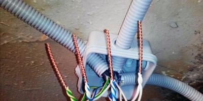
What we see after plastering the walls:

We take out the cables and clean the box. We cut the cables with a margin and make them the same length. I do about 70-90 mm, if measured from the wall.

Remove the insulation from the cable.

We clean the wires. The length of the bare copper section is about 30-40 mm

Then we twist it. It is convenient to do this with pliers. We bite off the ends a little.


We wrap a layer of electrical tape over the PPE, I use black fabric electrical tape.

Then we carefully stuff everything into the box. After puttying, the box will need to be closed with a lid.

Below are photos of the connection using Wago clamps.

We expose the wires; the length of the exposed copper section should be about 8-10mm.

We insert the wires into the clamps and snap them into place. Make sure that the clamp holds the conductors well.

Then, carefully put everything into the box.

Connection creation mechanism
Wiring your home is not difficult. To do this you need to have the necessary knowledge and equipment. The equipment is purchased in the store; you don’t even need to buy knowledge. At the very beginning, a diagram of the electrical network should be drawn up. In most cases, the owner of the construction hires an electrician who does not imagine the future location of the furniture and, as a result, switches are covered by doors, sockets in the corners are covered by furniture.
- As a rule, electricians draw diagrams with chalk on the wall of the future equipment, but it is better to place a diagram of the electrical network with the placement of electrical current collectors on the floor plan as a separate drawing, including the switching (connection) of the power cable cores in the distribution box - this will help:
- calculate the load on the electrical network;
- wire cross-section;
- divide consumers into groups.
- In terms of a household electrical circuit, there are at least two groups of electrical consumers:
- lighting;
- power part, that is, sockets.
It is best that these two circuits are mounted with separate power cables. If you plan to install powerful electrical appliances: electric stove, oven, boiler - these devices must have their own separate circuit, i.e. separate switch, fuse and cables.
Connection of wires in the junction box according to the PUE
PUE is a collection of regulatory documentation for the design and installation of electrical circuits; in fact, it is a desktop Bible for all people who begin to engage in electrical work. The collection shows the basic principles of creating circuits, the rules for their calculation, protection and communication devices. Further, all descriptions of electrical devices will be in accordance with the rules according to the PUE.
Selecting the cross-section and brand of wire
To lay electrical wiring in rooms and connect wires in a junction box, according to the PUE, the conductors must have a different color insulating coating, from the same manufacturer with the same color scheme. For wiring, it is best to use VVGNG brand wire - single-core copper, flat, double insulated, best with the additional designation NG, which means non-flammable.
It is best to purchase a cable from a well-known manufacturer, which must have a certificate. There is no need to take a wire without markings; electrical wiring in the house is, first of all, safety and is done for more than one year, so saving is inappropriate here. It must be taken into account that a copper cable with the same cross-section can withstand one and a half times more load than aluminum.
Attention! For a capital circuit, you cannot use a multi-core PVS or ShVVP cable. Although these wires are soft and more convenient to lay, they have a higher current resistance, and accordingly they will heat up more when a load is connected.
Power calculation
One of the basic rules for calculating a cable: 1 sq. mm is used in the calculation - 9 A. of electric current, that is, a cable with a cross-section of 1 mm can withstand the load of a kettle or iron with a power of 2 kW.
- Based on these recommendations, at least the following should be used for wiring in the house:
- lighting core is 1.5mm square, which corresponds to 10 - 12A;
- sockets in rooms are 16A, which corresponds to a cross-section of 2.5 mm. sq.
- kitchen electric ovens, the wire for which must withstand 25A. - this is a 4mm section. kv;
- The core of a four-burner electric stove must withstand 32A. - cross section 6 mm2.
Correct choice of electrical connection. wires in the junction box depends on its cross-section.
Attention! You cannot use electrical cables from different manufacturers, as they have different specific (ohmic) resistance per 1 linear meter.
Electrical junction box and wire connection
After laying the wires, according to the drawn up diagram, they must be connected to each other. In order for the connection to be in one place, there are communication boxes (distribution boxes). Depending on the installation, device connections can be round or square, deep or shallow, and are divided into internal (for hidden wiring) and external according to the method of fastening.
According to the requirements of the PUE, the electrical cable must extend at least 15 cm from the ceiling, taking into account all canopies. At the same distance, a device for switching cable cores is also attached. To install the internal box, a niche corresponding to the outer diameter of the sleeve is drilled in the wall; for external mounting, it is made directly to the wall.
How many wires can you twist in a junction box? You should not skimp on junction boxes and try to put as many wires there as possible - it will be inconvenient to connect, and all of them may not fit. As a rule, 3-4 wires are inserted into one junction box.Basic wiring diagrams
When making connections in a junction box, knowing how to connect the wires is not everything. You need to figure out which wires to connect.
How to connect sockets
How to wire a socket from a distribution box? As a rule, the socket group runs on a separate line. In this case, everything is clear: you have three cables in the box, each with three (or two) conductors. In this case, usually brown is the phase wire, blue is neutral (neutral), and yellow-green is ground.In another standard, the colors may be red, black and blue. In this case, the phase is red, blue is neutral, green is ground. In any case, the wires are collected by color: all of the same color in one group.

How to disconnect a junction box. The wires brought into the junction box are folded, stretched, and cut so that they are the same length. Do not cut short, leave a margin of at least 10 cm so that if necessary you can re-seal the connection. Then the conductors are connected using the chosen method.
If only two wires are used (in old houses there is no grounding), everything is exactly the same, only there are two connections: phase and neutral. By the way, if they are the same color, first find the phase (with a probe or multimeter) and mark it, at least by wrapping a piece of electrical tape around the insulation.
If there is a switch, the matter is more complicated. There are also three groups, but their connection is different.
- Eat:
- input - from another junction box or from a panel;
- from the chandelier;
- from the switch.

How should the circuit work? Power - “phase” - goes to the switch key. From its output it is fed to the chandelier. In this case, the chandelier will light only when the switch contacts are closed (the “on” position). This type of connection is shown in the photo below.
Connecting a single-key switch in a distribution box
If you look carefully, this is what happens: the phase with a light wire goes to the switch. It leaves from another contact, but this time blue (do not mix it up) and connects to the phase wire that goes to the chandelier. Neutral (blue) and ground (if network) are twisted directly.
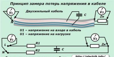
Testing wire connections in junction boxes
After all connections have been made, the exposed sections of the conductors are insulated using heat-shrinkable tubing, and the wires are laid in junction boxes. The boxes themselves are left open until the installed electrical wiring is tested. First, voltage is supplied to the connected lines by turning on the corresponding circuit breakers.
If, after switching on, nothing sparked anywhere and the machine was not knocked out due to a short circuit due to an erroneous connection of wires or poor-quality insulation of connections, the electrical wiring is tested with load current (loading), which is carried out by connecting various electrical appliances to the mounted lines. It is recommended to load each line with the maximum permissible current.
The download should continue for some time (preferably several hours). During this period, possible electrical installation defects will have time to manifest themselves. A visual inspection of the connections in the junction boxes should be carried out - signs of high temperature will be visible by melting of the insulation or terminal blocks. It is also important that there is no characteristic odor of overheated or burnt insulation.
After relieving the voltage, you should check all connections by touch - they should not be hot. If, when loading electrical cables with the maximum rated current for several hours, no comments are identified regarding the operation of the connections, then the electrical installation is considered normal, the junction boxes can be closed and the wiring can be put into operation.
Connecting the wires in the junction box requires special care. Not only the reliable operation of electrical appliances, but also the safety of the premises depends on how correctly the work is done.
Wires from the electrical panel are distributed to individual rooms of the apartment or house. Moreover, each room usually has not one, but several connection points (sockets and switches). To standardize the connection of conductors and concentrate them in one place, distribution boxes are used (their other names are “junction boxes” or “branch boxes”). The boxes contain cables from all consuming devices.

The wires in the box are not laid chaotically, but in accordance with clear rules prescribed in the Electrical Installation Rules (PUE). According to the requirements of the PUE, all connections of wires in the box, as well as branches, are made only inside the junction box. The conductors are directed along the top of the wall, but no closer than 15 centimeters from the ceiling. When the cable reaches the branch section, it descends strictly vertically. At the branch site there is a distribution box. The connections in it are made according to the existing diagram.
Junction boxes are classified by installation type. There are internal and external junction boxes. There is a niche in the wall for hidden-mounted boxes. Only the cover remains on the surface, which is installed flush with the finishing material. It is allowed to cover the lid with decorative panels. If the thickness of the walls or other circumstances do not allow the installation of an internal junction box, it is mounted directly on the wall.

The distribution box can be rectangular or round. The number of pins is usually four, but in some cases there are additional pins. Each outlet is equipped with a fitting or thread for securing a corrugated hose. The presence of such a hose or plastic pipe greatly simplifies the process of laying and replacing wires. To replace the wires, it will be enough to disconnect the hose or pipe from the junction box and the consumer, and then pull it out. After replacing the conductors, the hose is returned to its place. If the wires are located in a groove, you will need to break up the layer of plaster, which is much more labor-intensive.
The use of junction boxes leads to the following positive results:
- The maintainability of the electricity supply system increases. Since all connections are easily accessible, it is much easier to find the damaged area.
- The overwhelming majority of faults are found at joints. Since all connections are concentrated in one place, it is easier to carry out preventive inspections.
- Thanks to junction boxes, the degree of fire safety increases.
- The use of junction boxes allows you to save money and reduce labor costs when laying cables.
Methods for connecting conductors
There are many options for connecting wires in a junction box. The choice of a specific method depends on the following factors:
- the material from which the cores are made (steel, copper, aluminum);
- environmental conditions (outdoor/indoor, working in land or water, etc.);
- number of wires;
- coincidence or mismatch of the cross-section of the cores.
Taking into account these parameters, the most suitable technique is selected.
The following methods are used to connect wires in the junction box:
- terminal blocks;
- Wago spring terminals;
- self-insulating clips (PPE, or plastic caps);
- twisting;
- crimping with sleeves;
- soldering;
- "nuts";
- bolted connections.
Below we will consider the features of each of the listed methods.
Terminal blocks
Terminals are devices made of plastic, the inside of which contains a brass bushing. There are screws on both sides of the bushing.

To connect the wires to each other, you need to insert a conductor on each side of the terminal block and secure them tightly with screws. This joining method is most common in distribution boxes, as well as when installing lighting fixtures, sockets and switches.
Note! The inlet holes of the terminal blocks differ in diameter depending on the cross-section of the conductors intended for them.
Advantages of the method:
- low cost of terminal blocks;
- simplicity and convenience of installation work;
- reliability of conductor fixation;
- the ability to connect poorly compatible materials such as copper and aluminum.
Disadvantages of the method:
- The pads offered for sale are often of low quality, which is discovered during mating and forces the products to be rejected.
- Only two wires can be connected.
- Terminal blocks are not suitable for aluminum or stranded conductor because aluminum is brittle and the stranded conductor strands are too thin.
- Although the method is reliable, a better connection can be obtained, for example, by soldering.
Wago terminals
Wago spring terminal blocks are one of the most popular devices used in connecting wires.

Unlike standard terminal blocks, in Wago docking is carried out not with screws, but with the help of a special mechanism. The device is equipped with a lever that allows you to secure the conductor while maintaining its integrity. Before using Wago, you need to remove the insulating layer. Next, the cores are directed into the block hole.
Note! There are both disposable and reusable pads on the market. Disposable fasteners mean that they can only be used once, and if the wire is replaced, the pads become unusable. Reusable terminals are more expensive, but can be easily removed and then reused for their intended purpose.
Advantages of Wago spring pads:
- You can connect both conductors from the same metal and dissimilar materials.
- It is possible to connect multiple cores (three or more).
- When fixing multi-core conductors, thin wires do not break.
- The pads are small in size.
- Working with pads does not take up extra time, the process is not labor-intensive.
- The fastening is of high quality.
- The block has a hole for an indicator screwdriver to monitor the functioning of the electrical network.
Wago has one drawback - the high cost of products.
Self-insulating clips (PPE)
A self-insulating clip (or connecting insulating clip) is a plastic cap, inside of which there is a special spring for fixing the wire.

The advantages of PPE include the following characteristics:
- Low cost.
- The products are made from non-flammable plastic, therefore, there is no danger of spontaneous combustion of electrical wiring at the junction point.
- Easy installation.
- A wide variety of color shades, which allows you to color-code phase, neutral and ground.
The disadvantages of PPE include:
- low fastening and insulating qualities;
- impossibility of using for connecting aluminum and copper conductors.
Crimping with sleeves
Connecting wires in a junction box using sleeves is considered a method that ensures high quality connections. The essence of the technique is to place the stripped cores in a special tube (sleeve), which is then subjected to crimping by crimping. Next, the sleeve is treated with insulating material, for which heat-shrinkable tubing or regular insulating tape is used. Wires can be inserted from both ends of the tube, or only from one end. In the first case, the joint will be located in the middle part of the sleeve, but in the second case it is necessary that the total cross-section of the cores is no larger than the cross-section of the sleeve.

Advantages of crimping:
- The connection is of high quality and reliable insulation.
- Affordable prices for sleeves.
Disadvantages of crimping:
- The sleeve cannot be replaced once removed - it is a one-time use attachment.
- The connection will require the use of specialized tools (crimping pliers, pipe cutter).
- Crimping of aluminum and copper wires is possible only with the help of a specially designed sleeve.
- The work is labor intensive.
Soldering
Connection using soldering is considered the highest quality of all possible. Before docking, you need to thoroughly clean the conductors. Next, the bare ends are treated with molten solder, after which the wires are immersed in the bath. When the conductors have cooled, insulating material (cambric or electrical tape) is applied to them.
Note! The cooling process should not take place in cold weather, since as a result of too rapid cooling, the material will become covered with microcracks, which will greatly deteriorate the quality of fixation of the conductors.
As already mentioned, the main advantage of soldering is the unsurpassed quality of the connection.
Disadvantages of the technique:
- A specialized tool is required, as well as skills to handle it.
- The work requires significant labor costs.
- The connection is permanent, that is, disposable.
- There are restrictions on the use of soldering, which are detailed in the PUE.
- Over time, soldering resistance increases, which is reflected in the form of voltage loss and electrical conductivity.
Thus, despite the reliability of the connection, specialists rarely turn to soldering.

Welding is sometimes used instead of soldering. The essence of this method is the same as in the case of soldering. The only difference is the need for different skills, namely the ability to work with a welding machine.
Twist
Connecting wires in a junction box using the most primitive method - twisting - is not used so often due to significant limitations: poor quality of fastening and the impossibility of joining aluminum and copper conductors. However, twisting is still sometimes found, since it is attractive due to its ease of implementation, as well as the lack of financial costs. Most often, twisting is used when laying temporary electrical wiring. It is recommended to use cambrics as an insulating material.
Note! Twisting is unacceptable in rooms with high humidity, as well as in wooden buildings.
Walnut clamp
The “nut” is a cable clamp with two plates and four bolts in the corners. Before connecting, the insulation is removed from the wires. Next, the conductors are fixed in the plate and covered with a carbolite shell.

Benefits of "nut":
- Low costs.
- Installing the “nut” is not very difficult.
- It is possible to connect dissimilar materials (aluminum and copper).
- High quality insulation.
Disadvantages of this method:
- The fasteners weaken over time and need to be tightened regularly.
- The “nut” is not the best method of mounting in a distribution box due to the excessive dimensions of the connection.
Bolted connection
Bolting is a very simple but effective way of connecting conductors to each other. To complete the job, you only need a bolt, three washers and a nut. The diagram for connecting the wires in the junction box using a bolt is shown in the picture below.

A washer is threaded onto the bolt thread. Next, the core is wound (the insulation must first be removed). After this, the thread is laid with a second washer and another core. At the end, a third washer is placed, which is pressed with a nut. The connection must be covered with insulating material.
The bolted connection has the following advantages:
- low cost;
- ease of implementation;
- the ability to connect products made of copper and aluminum.
Disadvantages of connecting conductors with bolts:
- Insufficient quality of fixation.
- You will need a lot of insulating material.
- The bolt is too large and may not fit into the junction box.
Solving other problems
The connection of stranded wires has a number of features.
Connecting many wires
Options for connecting two contacts were discussed above. If we are talking about connecting multiple contacts, it is recommended to choose among the following options (in order of priority - from the best method to the worst):
- Wago terminal blocks;
- crimping with sleeves;
- rations;
- twists;
- insulating tape.

The rules for docking using the indicated methods, as well as their advantages and disadvantages, are discussed above.
Docking of cores with different sections
To combine cores of unequal cross-sections in a junction box, you will need Wago terminal blocks, although you can get by with standard terminal blocks - the latter option will be cheaper. In this case, it is necessary to secure the cores tightly using a screw or lever.
Note! If the wires not only have different sections, but are also made of different metals, you will need special pads, inside of which there is a special composition to prevent oxidative processes. Similar pads are available in the Wago range.
Cores with different sections can also be secured by soldering.
Joining of stranded and single-core conductors
The combination of conductors with one and multiple cores is carried out in the same way as all others. In this regard, you can choose any of the above methods, but the highest priority is soldering or terminals (preferably Wago).
Procedure for carrying out work in land and water
It is not so rare that there is a need to lay electrical wiring underground or underwater. Let us briefly dwell on the features of performing electrical installation work under these conditions.
Wires can be laid in water, for example, when installing a submersible pump. In this case, soldering of the wire ends is necessary. Next, the connection is treated with insulating material (hot glue), and heat shrink is put on top. If the technology is followed, the joint will be very reliable and safe. However, if you are careless, it will end in a short circuit.
Wiring in the ground is protected in the same way as described above, however, to obtain a secure connection, a more advanced technique can be used. The ends of the cable should be pressed with a terminal block, and the sealed junction box should be filled with silicone. It is recommended to place the underground pipeline in a durable box or pipe to prevent acts of pestilence by rodents. Damaged cable ends are best joined using couplings.
Basic wiring diagrams
Above we talked in some detail about how to connect the wires in the junction box. However, the work is not limited to connecting wires in the junction box. You also need to connect the wires to sockets and switches.
Connecting sockets
A group of sockets is usually separated into an independent line. There are three wires in the box, each of which has a color specific to its purpose. Brown is usually live, blue is neutral, and green/yellow is ground. In some cases other colors are used. For example, phase is red, zero is blue, ground is green.
Before laying, the wires are laid out to their full length and trimmed so that they are the same length. It is necessary to have 10-12 centimeters of reserve - just in case. The connection of conductors is carried out using one of the methods described above.
If only a pair of wires is involved (where grounding is not used), then we are talking about neutral and phase. If the conductors are the same color, you first need to find the phase using a multimeter. For convenience, it is better to mark the phase wire with electrical tape or a marker.
Connecting a one-button switch
In the case of a switch, there are also three groups, but the connection is made a little differently. There are three inputs: from the junction box or electrical panel, from the lighting fixture, from the switch. The phase wire is connected to the switch button. From the output of the switch the wire is directed to the lamp. In this case, the lighting device will only work when the switch contacts are closed.
Connecting a two-button switch
In two-key switches, the circuit is somewhat more complex. A three-wire cable must go to the switch serving two groups of lighting fixtures (if grounding is not used). One conductor is assigned to the common contact of the switch, the remaining two are directed to the output of the buttons. The phase is combined with the common contact of the switch. The neutral wires from the input and two groups of lighting fixtures are connected. Phase wires from lighting fixtures and two conductors from the switch are combined in pairs: one from the switch to the phase of one of the lamps, the second from the switch to the other lamp.
The correct connection of the wires in the junction box is largely the key to the reliability of your electrical network. Indeed, unlike connections in a distribution board, distribution boxes or, as they are also called, junction boxes are more closed for maintenance and contact connections here are much more difficult to check. That is why, even at the installation stage, maximum attention should be paid to their quality and correctness.
Before connecting wires in the junction box, we advise you to study the rules for their installation. After all, it is important not only to properly connect the wires to each other, but also to correctly insert them into the junction box, and also conveniently position them for possible inspection or repair.
Rules for installing wires in a junction box
First of all, let's look at the rules for the arrangement and installation of wiring in the distribution network. After all, it is with this factor that any installation begins.

So:
- First of all, you should remember that no more than eight groups of wires can be laid in one groove, box or pipe.
- All connections must be made in accordance with paragraphs 2.1.17 - 2.1.30 PUE. These clauses provide for a whole range of restrictions. First of all, remember that the wire in front of any contact must have a reserve sufficient for at least one reconnection.
- Before connecting the wires in the junction box, make sure that they are free from tension.. Or that this tension will not occur due to temperature changes.
- Any wire connection points must be accessible for repair and inspection.. At the same time, these places should be organized so that inspection is not hampered by structural elements.
- Any connection must be insulated. In this case, this insulation must correspond to the level of the main insulation. To achieve these parameters, it is better to use electrical tape or heat shrink.
- The distribution boxes themselves must be made of fireproof or fire-resistant materials, as in the video. This is especially true for the installation of wiring on combustible structures, which are subject to additional requirements.
Options for connecting wires in a junction box
First, let's look at how to connect the wires in a junction box. After all, it is the contact connections that are often the most vulnerable point of any electrical network and any shortcomings appear very quickly.
According to clause 2.1.21 of the PUE, all connections of wires and cables must be made by welding, soldering, crimping, screw or bolt compression. Other connection methods, especially twisting, are not allowed. Based on this, let's look at each of the possible connection methods separately.

So:
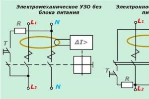
- The most reliable connection of wires is considered to be the welding method.. It has the lowest transition resistance, resulting in virtually no increased heating. In addition, over time, such a compound does not lose its properties.
Welding of wires in the junction box is carried out using a special welding transformer and a carbon electrode. The cost of such products is high enough for a simple replacement of wiring in an apartment, so you can often find homemade devices. Typically these are transformers up to 600 W and voltage 9 - 36V.
- The second place in reliability is the connection using the soldering method. This method is more accessible for home use because it does not require special equipment other than a regular soldering iron.

Soldering of wires in the junction box is carried out using conventional technology and does not impose any special requirements. The only point worth paying attention to is the quality of such connections. After all, if heated, the tin will heat up quickly enough and the contact will disappear. To prevent this, soldering is often combined with a twisted connection.
- Wire crimping has recently become increasingly popular. After all, a large number of fairly cheap tools for crimping wires have appeared on the market, and the price of consumables for this method is quite low.

- But the most common method is still the screw or spring clamp method. A huge number of buses and terminals currently on the market allow for a fairly reliable connection of wires.
Reading time ≈ 4 minutes
One of the important stages of electrical wiring installation is the connection of wires in the electrical junction box, which follows immediately after laying the cable. At first glance, some may think that using a junction box to connect wires is essentially a waste of time, but this assumption is wrong for several reasons.
Wire connection diagram in the junction box
During operation of the electrical wiring, malfunctions may occur - for example, a circuit break has occurred. If during electrical installation the workers did without distribution boxes, and the joints were simply rolled up with a finishing material such as plaster, then in order to get to the connections again, they will have to disturb the external finish - tear off the wallpaper, break a layer of plaster, etc. It is unlikely that anyone will be satisfied with such prospects. If in the future you need to install additional sockets, then in such cases it is not always convenient to pull wires from previously installed sockets; it is easier to organize the connection directly to the box.

If the wires are connected using terminal blocks, then you will have to drill a fairly deep channel into the wall, which is much more labor-intensive than simply connecting the wires in a junction box.

Finally, from a fire safety point of view, the advantage of using junction boxes is undeniable. For the correct organization of electrical installation work, there are special Rules for the Construction of Electrical Installations (PUE), which also regulate the procedure for connecting electrical wires.
Methods for connecting wires in a junction box

According to these rules (PUE), there are the following methods for connecting wires in a junction box:
- Connection using terminal blocks is the most preferred method: the terminal blocks are small in size and can easily fit into the distribution box, and it is not difficult to buy them. All that remains is to cut the wires to a certain length, connect the corresponding wires and place the resulting assembly in the box.
- Connecting wires in a junction box soldering method- a method more suitable for professionals who have sufficient experience in carrying out such a procedure. Without experience, a person will spend a lot of time on soldering, and it is not a fact that the result will be a high-quality connection.
- Connecting wires in the distribution box crimping method can be considered the most reliable permanent connection. However, this is quite labor-intensive work that requires skills, special devices and materials - these are press jaws, copper or aluminum sleeves and heat-shrinkable tubing. Pre-stripped conductors should be inserted at both ends of the sleeve until they stop and the connection should be crimped. Immediately before crimping, a heat-shrink tube should be put on one of the switched wires, and after crimping, slide the tube onto the sleeve and heat it to the shrinkage temperature.

The twisting method is the simplest connection option. However, if we talk about whether such a connection of wires in a junction box is reliable, PUEs allow such a method only as a temporary one and prohibit twisting without subsequent full modification of the connection.
For those who are faced with such a task as connecting wires in a junction box for the first time, the photos and videos presented in the article will help to visualize as clearly as possible how this procedure is carried out in all the ways listed above.

The main wiring elements switched in the box are lamps and sockets, and the wire connection diagram in the distribution box will be different for them. The socket will require a simple connection of wires by color. There will be three colors in total: phase (gray, brown or black), zero (blue or cyan), ground (yellow with a green stripe). There are also wires without grounding, then the cable will be two-core, and instead of three colors there will be two. For a lamp with a single-key switch, only 2 wires will need to be connected in the box: the zero will be connected to the wire going directly to the lamp, and the phase will pass to the lamp through the switch. For a chandelier with a 2-key switch, the only difference will be that in this case, 2 wires will go to the chandelier from the switch, responsible for different groups of light bulbs, and the zero will remain common.
Video of connecting wires in a junction box
Did you know that 70% of errors occur when installing electrical wiring because those who take on this work without experience have no idea how to connect the wires in a junction box. But if performed incorrectly, there may be weak contact, or it may disappear altogether. Most often, this kind of problem associated with an unreliable connection occurs in junction boxes or sockets, in lamps, in switches. This can also occur due to an unacceptably large load due to the connection of powerful electrical appliances.
How should the wires be connected?
The generalized answer is simple - so that there is good contact. Let's look at a few common methods:
- twist;
- crimping;
- welding;
- soldering;
- screw terminals;
- bolted;
- self-clamping.
Now in more detail.
Twist

According to the seventh edition of the regulatory document PUE, in Chapter 2, paragraph 2.1/21, twisting is officially prohibited. Therefore, there is no need to talk about the reliability of such fastening for wiring designed for heavy loads, since the contact area is small, and when heated, such a connection can weaken even more.

For crimping, a connecting sleeve is used. It is selected according to the diameter of the bundle, and whether it is aluminum or copper depends on the material from which the wire is made. Reliability is ensured by compressing this sleeve using a special tool - press pliers (pliers cannot be used for these purposes). This technology is in accordance with the requirements of regulatory documents.
Operating procedure:
- Considering the length of the sleeve, remove the insulation.
- Twist the wires into a bundle and insert them into the sleeve.
- Crimp with press pliers.
- Insulate with electrical tape or heat shrink.

Thanks to the use of the fusion method, it turns out to be a solid wire that is not afraid of oxidation, and, of course, such a connection will not weaken over time.
To perform such work, in addition to the ability to operate welding equipment, you will need:
- 24-volt welding machine with a power of at least 1 kW;
- carbon electrode;
- flux, which will subsequently protect the melt from exposure to oxygen;
- welding glasses;
- welder gloves.

With all this in place, the welding process itself is not particularly difficult. Remove the insulation and sand the wires until shiny. After twisting, pour flux into the recess of the electrode, pressing the wires against it, and hold it until a ball is formed, which is called the “contact point”. Clean it from flux, polish and insulate it.

This method differs from welding in that it uses solder melted with a soldering iron.
The fastening is reliable, but is not suitable for use in places where the wire can become very hot.
Also, such a connection will not be reliable under mechanical stress. You also need to know how to solder, otherwise the unheated wire will tear under tension load.
To work you will need:
- soldering iron;
- solder (tin-lead);
- flux (rosin);
- a special brush with which flux is applied to the core;
- fine sandpaper.

Soldering technology differs from welding only in that it is not the metal itself that melts, but the solder, which must be monitored so that when melted, it flows into the twist. Copper wires are mainly connected by soldering, but if you have special solder, you can also solder aluminum.

Screw clamps can be used to connect different metals for which contact is contraindicated, since they come into contact with each other in the presence of moisture (copper with aluminum). Due to their compactness and ease of operation, they have found application not only for the contact of dissimilar metals. In addition, their use is permitted and provided for by regulatory documents, however, they have a significant drawback - when used for aluminum wires, the latter must be periodically crimped.
Bolted connections

This type is very bulky and is not suitable for hiding in a junction box. When using it for dissimilar metals, you need to insert a steel washer between them. The method is very simple and the connection can be made from scrap materials. A washer is put on the bolt, then one of the wires, then another washer, the second - and all this is tightened with a nut. Naturally, everything needs to be insulated, which will further increase the size.
Self-clamping connections

Today, such clamps are the most popular, as they are easy, convenient and quick to work with. In addition, inside such connections there is a paste that prevents the metal from oxidizing, so dissimilar metals can be inserted into the block without fear of them oxidizing.
Video
We bring to your attention a video on the topic of our article.