The operating principle of the Levitron toy, which clearly demonstrates the state of weightlessness, is based on the action magnetic field, holding small objects in the air.
Such toys, unfortunately, are not yet produced by the domestic industry, so the demand for them cannot be satisfied. There is, of course, the opportunity to order Levitron from abroad, but the cost of the toy (already quite high - $35) increases significantly due to the delivery price.
But nothing can stop you from making a Levitron with your own hands using one of two well-known methods: using an electromagnet or using permanent magnets.
The second of these methods is much simpler than the first, moreover, it does not require specific knowledge in the field of physics, and this device also does not need electrical power.
Materials for making Levitron
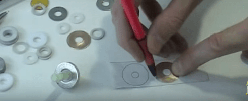
So, to make a toy, we need three ring-shaped magnets with sufficient power. Magnets from low-frequency speakers whose service life has long expired are quite suitable for our purpose.
In order to make a top, you will need a neodymium magnet. You can take it from the speaker, which has the inscription “Neodium transducer”. Similar speakers are used in cell phones. The strongest permanent magnet today is neodymium, created from an alloy that includes neodymium, boron and iron. Heat will negatively affect it, so this magnet should be protected from heat. So the magnet is from cell phone It may be of two types - in the form of a round plate or in the form of a ring. A ring magnet is placed on the top itself strictly in the center, and a tablet-shaped magnet is glued to the axis of the top from below. The material for the top itself should be a lightweight material, such as a composite or plastic.
Setting up Levitron
The setup should be approached with particular scrupulousness, because this part of the work is crucial and is the most labor-intensive. Ring magnets must be connected to each other with opposite polarities. A plate (not made of metal) up to 1 cm thick should be installed on top of them. The top will be carefully installed at the base of the Levitron - the center of the magnet. If you notice that the top deviates to the side, then the magnet needs to be replaced with another one with a larger diameter.
To launch the top, you will need several more elements with which you can adjust the thickness of the platform in order to achieve normal rotation of the top. We will need plexiglass plastic with paper sheets. If the top is spinning normally, we begin to smoothly lift the platform until it flies up.
If our top flies up too quickly, its weight should be increased. If it deviates in one direction, then the situation can be corrected by placing paper sheets under the opposite direction. These steps allow us to adjust the base of our toy so that it is clearly at sea level.
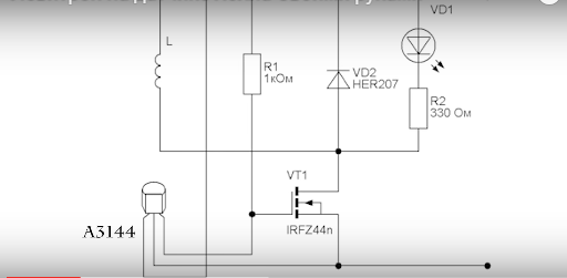
Working principle: In this circuit, an attractive force is generated between an electromagnet and a permanent magnet. The equilibrium position is unstable, and therefore an automatic monitoring and control system is used. The control sensor is a magnetically controlled position sensor based on the Hall effect MD1. It is located in the center of the end of the coil and is secured. The coil is wound with varnished wire 0.35-04 mm, and has about 550 turns. LED HL1 shows by its glow that the circuit is working. Diode D1 ensures the speed of the coil.
The scheme works as follows. When turned on, current flows through the coil, which creates a magnetic field and attracts the magnet. To prevent the magnet from turning over, it is stabilized by attaching something to it from below. The magnet takes off and is attracted to the electromagnet, but when the magnet gets into the range of the position sensor (MD1), it turns it off with its magnetic field. The sensor, in turn, sends a signal to a transistor, which turns off the electromagnet. The magnet falls. Having left the sensitivity zone of the sensor, the electromagnet turns on again and the magnet is again attracted to the electromagnet. Thus, the system continuously oscillates around a certain point.
Scheme:
For assembly we need:
1) resistors 270Ohm and 1kOhm (0.125W)
2) transistor IRF 740
3) LED
4) diode 1N4007
5) Hall sensor AH443
6) development board
7) varnished wire 0.35-0.4mm
+ case, soldering iron, etc.
Scheme:
We assemble the coil. The frame can be made using a thin sheet of fiberglass and an old felt-tip pen.
Cut out: (approximate coil size: height - 22mm, diameter - 27mm)
Glue together:
We wind approximately 550 turns: (varnished wire 0.35-0.4mm, in bulk, but we try to wind more or less evenly)
Soldering the control board: (I used a regular 3.5 mm miniJack as a power connector)
Pinout:
For ease of assembly, you can use pin connectors:
We cut out all the necessary holes in the body:
Let's put everything in its place:
Now you need to make a mount for the coil:
We screw it to the body and attach the coil:
This is how you need to bend the Hall sensor, solder the wires to it:
Let's connect everything to the heap:
After we take out the magnet, we need to determine which side to orient it towards the electromagnet. To do this, we place and temporarily fix the Hall sensor at the very bottom of the coil. We turn on the Levitron (the LED should light up) and bring the magnet. If it is attracted to the coil, then the magnet is oriented correctly, but if the magnetic field of the coil pushes it out, then the magnet must be turned over. Something lightweight needs to be attached to the bottom of the magnet. In my case it's an LED.
By moving the Hall sensor we achieve stable hovering at the maximum distance from the coil. Let's fix it:
Levitron, as you know, is a top rotating in the air above a box in which a source of magnetic field operates. You can make a Levitron from a popular hall sensor.
What is Levitron
ATTENTION! A completely simple way to reduce fuel consumption has been found! Don't believe me? An auto mechanic with 15 years of experience also didn’t believe it until he tried it. And now he saves 35,000 rubles a year on gasoline!
Levitron is a toy. There is no point in buying it if you know the manufacturing options homemade device. There will be nothing complicated in the design of such a Levitron if there is a regular hall sensor, for example, purchased for a car distributor and left for future use.
You should know that the levitation effect is always observed in a fairly narrow zone. Such realities somewhat limit the freedom of action of craftsmen, however, with patience and time, you can always set up the Levitron efficiently and effectively. It will practically not fall or jump.
Levitron from hall sensor
Levitron for a hall sensor and the idea of its manufacture is simple, like everything ingenious. Thanks to the force of the magnetic field, a piece of any material with electromagnetic properties rises into the air.

To create the effect of “hovering”, floating in the air, the connection is made with high frequency. In other words, the magnetic field seems to lift and throw the material.
The design of the device is too simple, and even a schoolchild who has not sat through physics lessons in vain will be able to build everything on his own.
- You need an LED (its color is selected depending on individual preferences).
- Transistors RFZ 44N (although any field device close to these parameters will do).
- Diode 1N 4007.
- Resistors 1 kOhm and 330 Ohm.
- Actually, the hall sensor itself (A3144 or another).
- Copper winding wire measuring 0.3-0.4 mm (about 20 meters will be enough).
- Neodymium magnet in the form of a tablet 5x1 mm.
- 5-volt charger designed for mobile phones.
Now in detail about how the assembly is carried out:
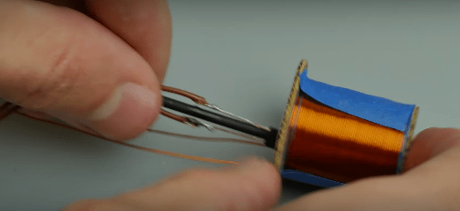
- A frame for the electromagnet is made with exactly the same parameters as in the photo. 6 mm is the diameter, about 23 mm is the winding length, 25 mm is the diameter of the cheeks with a margin. The frame is made from cardboard and a regular notebook sheet, using superglue.

- The end of the copper wire is fixed on the reel and then wound (approximately 550 turns). It doesn’t matter which way you wind it. The other end of the wire is also fixed, the coil is put aside for now.
- We solder everything according to the diagram.
- The hall sensor is soldered onto the wires and then placed on the coil. You need to insert it inside the coil and secure it with improvised means.
Attention. The sensitive area of the sensor (it can be determined from the documentation for the hall sensor) should look parallel to the ground. Therefore, before inserting the sensor into the coil, it is recommended to bend this place a little.
- The coil is suspended and power is supplied to it through a previously soldered board. The coil is fixed using a tripod.

Now you can check how Levitron works. Any electrified material can be brought to the coil from below. It will either be attracted to the coil or repelled, depending on the polarity. But we need the material to hang in the air, to float. This will be the case if the shape of the material is not too small in relation to the coil.
Note. If the tablet-shaped magnet is small, then it will not levitate very effectively. It may fall. To eliminate errors in work, you need to shift the center of gravity of the material to the bottom - an ordinary piece of paper will do as a load.
As for the LED, you don’t have to install it. On the other hand, if you want more effect, you can organize a backlit show.
Homemade Levitron in a classic version without a sensor
As you can see, thanks to the presence of a hall sensor, it was possible to produce a quite impressive toy. However, this does not mean at all that it cannot be done without a sensor. Against, homemade levitron in the classic version, it is only a large magnet from the speaker (13-15 cm in diameter) and a small ring magnet for the top (2-3 cm in diameter), without using a sensor.
The axis of the top is usually made from old pen or pencil. The main thing is that the rod is selected so that it fits tightly in the center of the ring magnet. The excess part of the handle is then cut off (about 10 cm in length along with the attached magnet for the top, which is what you need).
The classic manufacturing scheme for a Levitron also implies the presence of a dozen different washers cut from thick paper. What are they needed for? If in the case described above, paper was also used, and as we remember - to shift the center of gravity down or, more simply, for adjustment. It's the same here. Washers will be needed for ideal adjustment of the top (if necessary, they are placed after the ring magnet on the rod).
Attention. In order for a homemade top to levitate perfectly, in addition to adjusting it with washers, you need to not make a mistake with the polarity. In other words, install the ring magnet coaxially with the large magnet.

But that's not all. Both in the first case (using a hall sensor) and in the second, it is necessary to achieve ideal evenness of the source of attraction. In other words, placing a large magnet on an ideal flat surface. To achieve this, use wooden coasters of various thicknesses. If the magnet does not sit level, stands are placed on one side or on several sides, thus adjusting the evenness.
Platform Levitrons
The platform circuit of the Levitron differs, as a rule, by the presence of not one, but several source magnets. In this case, the material or top floating in the air will tend to fall onto one of the magnets, shifting from the vertical axis. To avoid this, you need to be able to adjust the central zone of attraction, and do it perfectly accurately.
And here those same coils come to the rescue, with a hall sensor inserted inside. Let there be two such coils, and they should be placed exactly in the middle of the platform, between the magnets. In the diagram it will look like this (1 and 2 are magnets).

From the diagram it becomes clear that the purpose of controlling the coils is to create a horizontal force, a center of gravity. This force is formally called Fss, and it is directed towards the equilibrium axis when a displacement occurs, indicated in the diagram as X.
If you connect the coils so that the pulse creates a zone with reverse polarity, you can solve the issue with the offset. Any physicist will confirm this.
Any old DVD player can be used as a housing for the platform Levitron design. All the “insides” are removed from it, magnets and coils are installed, and for beauty purposes, the upper part is closed with a practical lid made of thin, can be transparent material(transmitting magnetic field).
Hall sensors must protrude through the holes of the platform and must be soldered on the straightened legs of the connectors.
As for magnets, these can be round elements 4 mm thick. It is desirable that one of the magnets be larger in diameter than the second. For example, 25 and 30 mm.
There are more complex options Levitrons, made according to the scheme of spinning a top located inside a small globe. These Levitrons can also be built using Hall sensors - effective components that have made a whole revolution in the automotive industry and other areas of human activity.
0.Preface
I read all sorts of things on the Internet and decided to build my own Levitron, without any digital nonsense. No sooner said than done. I post the pains of creativity for everyone to see.1. Brief description
Levitron is a device that keeps an object in balance with the forces of gravity using a magnetic field. It has long been known that it is impossible to levitate an object using static magnetic fields. In school physics this was called a state of unstable equilibrium, as far as I remember. However, with a little desire, knowledge, effort, money and time, it is possible to levitate an object dynamically by using electronics as feedback.This is what happened:
2.Functional diagram

Electromagnetic sensors located at the ends of the coil produce a voltage proportional to the level of magnetic induction. In the absence of an external magnetic field, these voltages will be the same regardless of the magnitude of the coil current.
If there is a permanent magnet near the lower sensor, the control unit will generate a signal proportional to the magnet field and amplify it to the required level and transmit to PWM to control the current through the coil. Thus, there arises Feedback and the coil will generate a magnetic field that will keep the magnet in balance with the forces of gravity.
Something went wrong, I’ll try it differently:
- There is no magnet - the induction at the ends of the coil is the same - the signal from the sensors is the same - the control unit produces a minimum signal - the coil works at full power;
- They brought a magnet close - the induction is very different - the signals from the sensors are very different - the control unit produces the maximum signal - the coil turns off completely - no one is holding the magnet and it begins to fall;
- The beckoning falls - moves away from the coil - the difference in signals from the sensors decreases - the control unit reduces the output signal - the current through the coil increases - the induction of the coil increases - the magnet begins to attract;
- The magnet is attracted - it approaches the coil - the difference in signals from the sensors increases - the control unit increases the output signal - the current through the coil decreases - the induction of the coil decreases - the magnet begins to fall;
- It’s a miracle - a magnet does not fall and is not attracted - or rather, it falls and is attracted several thousand times per second - that is, it arises dynamic equilibrium- the magnet just hangs in the air.
3.Design
The main element of the design is an electromagnetic coil (solenoid), which holds a permanent magnet with its field.78 meters of enameled copper wire with a diameter of 0.6 mm are tightly wound onto a plastic frame D36x48, about 600 turns. According to calculations, with a resistance of 4.8 Ohm and a power supply of 12V, the current will be 2.5A, power 30W. This is necessary for selection external unit nutrition. (In fact, it turned out to be 6.0 Ohm; it’s unlikely that they cut more wire, but rather saved on the diameter.)
A steel core from door hinge diameter 20mm. Sensors are attached to its ends using hot-melt adhesive, which must be oriented in the same direction.
The coil with sensors is mounted on a bracket made of aluminum strip, which, in turn, is attached to the housing, inside of which there is a control board.
On the case there is an LED, a switch and a power socket.
The external power supply (GA-1040U) is taken with a power reserve and provides a current of up to 3.2A at 12V.
An N35H magnet D15x5 with a Coca-Cola can glued on is used as a levitating object. I’ll say right away that a full jar is not good, so we make holes at the ends with a thin drill, drain the valuable drink (you can drink it if you’re not afraid of shavings) and glue a magnet to the top ring.

4.Schematic diagram

Signals from sensors U1 and U2 are fed to the operational amplifier OP1/4, connected in a differential circuit. The upper sensor U1 is connected to the inverting input, the lower U2 is connected to the non-inverting input, that is, the signals are subtracted, and at the output OP1/4 we obtain a voltage proportional only to the level of magnetic induction created by the permanent magnet near the lower sensor U2.
The combination of elements C1, R6 and R7 is the highlight of this circuit and allows you to achieve the effect of complete stability; the magnet will hang rooted to the spot. How it works? The DC component of the signal passes through the divider R6R7 and is attenuated 11 times. The variable component passes through the C1R7 filter without attenuation. Where does the variable component come from anyway? The constant part depends on the position of the magnet near the lower sensor, the variable part arises due to oscillations of the magnet around the equilibrium point, i.e. from changes in position in time, i.e. from speed. We are interested in the magnet being stationary, i.e. its speed was equal to 0. Thus, in the control signal we have two components - the constant is responsible for the position, and the variable is for the stability of this position.
Next, the prepared signal is amplified at OP1/3. Using variable resistor P2, the required gain is set at the tuning stage to achieve equilibrium, depending on the specific parameters of the magnet and coil.
A simple comparator is assembled on OP1/1, which turns off the PWM and, accordingly, the coil when there is no magnet nearby. Very convenient thing, you do not need to remove the power supply from the outlet if you have removed the magnet. The response level is set by variable resistor P1.
Next, the control signal is supplied to the pulse-width modulator U3. The output voltage swing is 12V, the output pulse frequency is set by the values of C2, R10 and P3, and the duty cycle depends on the input signal level at the DTC input.
PWM controls the switching of power transistor T1, which, in turn, controls the current through the coil.
The LED1 LED may not be installed, but the SD1 diode is required to drain excess current and avoid overvoltage when the coil is turned off due to the phenomenon of self-induction.
NL1 is ours homemade reel, to which a separate section is devoted.
As a result, in equilibrium mode, the picture will be something like this: U1_OUT=2.9V, U2_OUT=3.6V, OP1/4_OUT=0.7V, U3_IN=1.8V, T1_OPEN=25%, NL1_CURR=0.5A.
For clarity, I am attaching graphs of the transfer characteristic, frequency response and phase response, and oscillograms at the output of the PWM and coil.


5.Selection of components
The device is assembled from inexpensive and accessible components. It turned out to be the most expensive copper wire WIK06N, for 78 meters WIK06N paid 1200 rubles, everything else taken together was much cheaper. There is generally a wide field for experimentation; you can do without a core, you can take thinner wire. The main thing is not to forget that the induction along the axis of the coil depends on the number of turns, the current through them and the geometry of the coil.Analog Hall sensors SS496A with a linear characteristic up to 840G are used as magnetic field sensors U1 and U2, this is just right for our case. When using analogues with a different sensitivity, you will need to adjust the gain at OP1/3, as well as check the level of maximum induction at the ends of your coil (in our case with a core it reaches 500G) so that the sensors do not become saturated at peak load.
OP1 is an LM324N quad operational amplifier. When the coil is turned off, it produces 20 mV instead of zero at output 14, but this is quite acceptable. The main thing is not to forget to choose from a bunch of 100K resistors those closest in actual value to install as R1, R2, R3, R4.
The values C1, R6 and R7 were chosen by trial and error as the most best option for stabilizing magnets of different calibers (N35H magnets D27x8, D15x5 and D12x3 were tested). The R6/R7 ratio can be left as it is, and the value of C1 can be increased to 2-5 µF if problems arise.
If you use very small magnets, you may not have enough gain, in which case reduce the value of R8 to 500 ohms.
D1 and D2 are ordinary 1N4001 rectifier diodes, any will do.
The common TL494CN chip is used as a pulse-width modulator U3. The operating frequency is set by elements C2, R10 and P3 (according to the 20 kHz scheme). The optimal range is 20-30 kHz, at lower frequencies the coil whistle appears. Instead of R10 and P3, you can simply put a 5.6K resistor.
T1 is an IRFZ44N field-effect transistor; any other one from the same series will do. When choosing other transistors, you may need to install a radiator; be guided by the minimum values of channel resistance and gate charge.
SD1 is a Schottky diode VS-25CTQ045, here I grabbed it with a large margin, a regular high-speed diode will do, but it will probably get very hot.
LED1 yellow LED L-63YT, here, as they say, it depends on taste and color, you can set them more so that everything glows with multi-colored lights.
U4 is a 5V L78L05ACZ voltage regulator for powering the sensors and operational amplifier. When using an external power supply with an additional 5V output, you can do without it, but it is better to leave the capacitors.

6.Conclusion
Everything worked out as planned. The device operates stably around the clock and consumes only 6W. Neither the diode, nor the coil, nor the transistor gets hot. I'm attaching a couple more photos and the final video:


7. Disclaimer
I'm not an electronics engineer or a writer, I just decided to share my experience. Maybe something will seem too obvious to you, something too complicated, and something you forgot to mention at all. Feel free to make constructive suggestions both on the text and on improving the diagram, so that people can easily repeat it if they so desire.A short video about what a made Levitron is like:
www.youtube.com/watch?feature=player_embedded&v=vypjmqq9...
If someone is not afraid to do the same interesting thing, then here you go detailed instructions:
A little theory
Let's start, perhaps, with the mechanical diagram of the platform Levitron, which has developed in my understanding. For the sake of brevity, I will here call the magnet that hovers above the platform the word “chip.”
Levitron platform sketch(above) is shown in Fig. 1.

In Fig. 2 – power diagram of a vertical section along the central axis of the platform (as I imagine it) at rest and without current in the coils. Everything is fine, except that the state of rest in such a system is unstable. The chip tends to shift from the vertical axis of the system and forcefully plop onto one of the magnets. When the chip “feels” the space above the magnets, a force “hump” is felt above the center of the platform with the top lying on the central axis.

mg – chip weight,
F1 and F2 are the forces of interaction between the chip and the platform magnets,
Fmag is the total impact balancing the weight of the chip,
DH – Hall sensors.
In Fig. 3. The interaction of the chip with the coils is depicted (again, according to my understanding), and the remaining forces are omitted.

From Figure 3 it can be seen that the purpose of controlling the coils is to create a horizontal force Fss, always directed towards the equilibrium axis when a displacement occurs X. To do this, it is enough to turn on the coils so that the same current in them creates a magnetic field in the opposite direction. There is only one small thing left: measure the displacement of the chip from the axis (the value X) and determine the direction of this displacement using Hall sensors, and then pass currents in the coils of suitable strength.
Simple repetition of electronic circuits is not in our traditions, especially since:
- two TDA2030A are not available, but TDA1552Q is available;
- there are no SS496 Hall sensors (available for about $2 apiece), but there are sensors similar to the HW101, 3 pieces for free in each CD or DVD drive drive;
- too lazy to bother with bipolar power supply.
Datasheets:
SS496 - http://sccatalog.honeywell.com/pdbdownload/images/ss496.seri...HW101- http://www.alldatasheet.com/datasheet-pdf/pdf/143838/ETC1/HW101A.html
The circuit consists of two identical amplification channels with differential inputs and bridge outputs. In Fig. Figure 4 shows the complete diagram of only one amplification channel. LM358 (http://www.ti.com/lit/ds/symlink/lm158-n.pdf) and TDA1552Q (http://www.nxp.com/documents/data_sheet/TDA1552Q_CNV.pdf) chips were used.

A pair of Hall sensors is connected to the input of each channel so as to supply a difference signal to the amplifier. The sensor outputs are connected in opposite directions. This means that when a pair of sensors is in a magnetic field with the same strength, a zero difference voltage is supplied to the amplifier input.
Balancing resistors R10 are multi-turn, old, Soviet ones.
In trying to squeeze a high enough gain out of the amplifier, I got banal self-excitation, presumably due to a mess on the circuit board. Instead of “cleaning”, frequency-dependent RC circuits R15C2 were introduced into the circuit; they are not required. If you still had to install them, then the resistance R15 must be selected to be the highest, at which the self-excitation goes out.
The power supply for the entire device is a 12V 1.2A adapter (pulse), reconfigured to 15V. Power consumption in normal condition (with the fan turned off) ended up being quite modest: 210-220 mA.
Design
The housing chosen is a 3.5” drive casing, which approximately corresponds to the dimensions of the prototypes. To level the platform
the legs are made from M3 screws.
A shaped hole is cut out in the upper part of the body, clearly visible in Fig. 5. Subsequently, it is covered with a decorative mirror plate made of chrome-plated brass, secured with screws from hard drives.

1 – installation locations for magnets (bottom) and balance indicators (optional)
2 – “pole pieces” of the coils
3 – Hall sensors
4 – backlight LEDs (optional)
Hall sensors are located in the holes of the fiberglass base of the platform and are soldered on the straightened legs of the connectors (I don’t know the type). The connectors looked like in Fig. 6.

The sensors are soldered from the CD or DVD drive motors. There they are located under the edge of the rotor and are clearly visible in Fig. 7. For one channel you need to take a pair of sensors from the same engine - this way they will be as identical as possible. Soldered sensors are shown in Fig. 8.


For the reels, plastic spools were purchased for sewing machines, but there was not enough space for winding on them. Then the cheeks were cut off from the spools and glued to pieces of thin-walled brass tube with an outer diameter of 6 mm and a length of 14 mm. The tube used to be a segment of a telescopic rod antenna. On four such frames, windings are wound with 0.3 mm wire “almost layer by layer” (without fanaticism!) until filled. Resistance is aligned at 13 ohms.
Magnets - rectangular 20x10x5 mm and disk magnets with a diameter of 25 and 30 mm, thickness 4 mm (Fig. 9) - I still had to buy... Rectangular magnets are installed under the base of the platform, and chips are made from disk magnets.

View of the device from below and from behind (upside down) - in Fig. 10 and 11 (one legend for both figures). The mess is, of course, picturesque...
The U2 TDA1552Q chip (3) is located on the heatsink (9), which previously worked on the video card. The radiator itself is fixed with screws on the bent parts top cover housings. The radiator (9) also has a power socket (1), control sockets (2) and a thermal control unit (5).
A piece of fiberglass, which used to be a keyboard, serves as the base of the platform. The coils (7) are secured to the base with M4 screws and nuts. Magnets (6) are attached to it using clamps and self-tapping screws.
The test sockets (2) are made from a computer power connector and are attached to the back of the device near the balancing resistors (10) so that they are easily accessible without disassembly. The sockets are connected, naturally, to the outputs of both channels of the amplifier.
The circuit of the preamplifier and its power stabilizer, including balancing resistors (10), is mounted on breadboard and as a result of adjustments it turned into a picturesque pigsty, which I had to refrain from taking macro photographs of.


1 – fastening the power socket
2 – control sockets
3 – TDA1552Q
4 – power switch
5 – thermal control unit
6 – magnets under the clamps
7 – coils
8 – magnetic shunts
9 – heat sink
10 – balancing resistors
Setup
Setting zeros at the outputs of both channels every time the debug is turned on is mandatory. Without fanaticism: +–20 mV is quite acceptable accuracy. There may be some mutual influence between the channels, so if the initial deviation is significant (more than 1-1.5 volts at the channel output), it is better to set zeros twice. It is worth remembering that with an iron case, the balance of a disassembled and assembled device is two big differences.
Checking channel phasing
The chip must be taken in your hand and placed above the center of the platform of the turned on Levitron at a height of approximately 10-12mm. Channels are checked one by one and separately. When moving the chip by hand along the line connecting the sensors opposite from the center, the hand should feel noticeable resistance created by the magnetic field of the coils. If resistance is not felt, but the hand with the chip is “blown away” from the axis, you need to swap the wires from the output of the channel being tested.
Adjusting the position of the floating chip
In videos about homemade platform Levitrons, you can often see that the chip floats in an inclined position, even if it is made on the basis of disk magnets, that is, it is quite well symmetrical. There was some distortion in the described design. Perhaps the metal case is to blame for this...
The first thought: move the magnets down on the side where the chip is too “propped up”.
Second thought: move the magnets further from the center on the side where the chip is excessively “propped up”.
Third thought: if the magnets are displaced, then the magnetic axis of the system permanent magnets the platform will be skewed relative to the magnetic axis of the coil system, which will cause the behavior of the chip to become unpredictable (especially if its weight is different).
The fourth idea: to make the magnets stronger on the side where the chip is tilted was discarded as unrealistic, because there was nowhere to get a wide range of magnets for fitting.
The fifth idea: making the magnets weaker on the side where the chip is too “propped up” turned out to be successful. Moreover, it is quite simple to implement. A magnet, as a source of a magnetic field, can be shunted, that is, part of the magnetic flux can be short-circuited, so that the magnetic field in the surrounding space becomes slightly weaker. Small ferrite rings (10x6x3, 8x4x2, etc.), freely picked out from dead space-saving lamps (8 in Fig. 10), were used as magnetic shunts. These rings just need to be magnetized to a too strong magnet (or two or three) on the side that is farthest from the center of the platform. It turned out that by selecting the number and size of shunts for each “too strong” magnet, you can quite accurately level the position of the floating symmetrical chip. Remember to perform electrical balancing after every change in the magnetic system!
Options
Options include: amplifier imbalance indicators, thermal control unit, backlight and adjustable platform legs.
Indicators of amplifier imbalance are two pairs of LEDs located at the same radii as the sensors, deep in the fiberglass base of the platform (1 in Fig. 5). LEDs, very small and flat, used to work in some kind of modem, but they will also work from an old mobile phone (in SMD version). The LEDs are recessed in the holes, since the chip, falling from the center, plops onto the nearest magnet and is quite capable of destroying the LED.
The indicator diagram for one channel is shown in Fig. 12. LEDs must have an operating voltage of 1.1-1.2 V, i.e. simple red, orange, yellow. At higher LED voltages (2.9-3.3 V for super-bright ones), the number of diodes in the D3-D6 chain should be recalculated to minimize the “dead zone” - the minimum voltage at the channel output at which none of the LEDs glows.

I positioned the indicators so that the one towards which the chip is offset from the center glows. Indicators help you easily hang the chip above the Levitron, as well as level the platform. In normal condition they are all extinguished.
The diagram of the thermal control unit is shown in Fig. 13. Its purpose is to prevent the final amplifier from overheating. At the output of the thermal unit, a 50x50 mm 12V 0.13A fan from the computer is turned on.

In the thermal unit circuit it is easy to recognize a slightly modified Schmitt trigger. Instead of the first transistor, a TL431 microcircuit was used. The type of transistor Q1 is indicated conditionally - I plugged in the first NPN I came across that could withstand the operating current of the fan. A thermistor found on an old motherboard in the processor socket was used as a temperature sensor. The temperature sensor is glued to the heatsink of the final amplifier. By selecting resistor R1, you can adjust the thermal unit to operate at a temperature of 50-60C. Resistor R5, together with the collector current Q1, determines the amount of hysteresis of the circuit relative to the voltage at the control input U1.
In the diagram in Fig. 13, resistor R7 is introduced to reduce the voltage on the fan and, accordingly, the noise from it.
In Fig. 14 you can see how the fan is embedded in the bottom cover of the case.

Another way to use a thermal unit is to connect the final amplifier chip to the MUTE control pin (Fig. 15). The value of the R5 value indicated on the diagram assumes that MUTE (pin 11 of the U2 chip in Fig. 4) is connected to the power supply through a 1 kOhm resistor (NOT directly, as in the datasheet!). In this case, a fan is not needed. True, when the MUTE signal is applied to the amplifier, the chip falls, and after the MUTE signal is removed, it (for some reason?) does not take off.

Backlight – 4 bright LEDs with a diameter of 3 mm, located obliquely to the center in the holes of the base of the platform and the decorative plate in those places where the chip does not fall. They are connected in series and through a 150 Ohm resistor to the general power supply circuit of the 15V device.
Conclusion
Load capacity
To “finish off” the topic, the “cargo characteristics” of the Levitron with chips 25 and 30 mm in diameter were removed. Here I called the cargo characteristics the dependence of the height of the chip hovering above the platform (from the decorative plate) on the total weight of the chip.
For a chip with a 25 mm magnet and a total weight of 19 g, the maximum height was 16 mm, and the minimum was 8 mm with a weight of 38 g. Between these points the characteristic is almost linear. For a chip with a 30 mm magnet, the load characteristic turned out to be between the points of 16 mm at 24 g and 8 mm at 48 g.
From a height below 8 mm from the platform, the chip falls, being attracted to the iron cores of the coils.
DO NOT do like me!
Firstly, you should not skimp on sensors. “Bare” Hall sensors, removed in pairs for each channel from two engines (that is, almost identical!) - still exhibit their outrageously large temperature coefficient of resistance. Even with the same power circuits and counter-differential connection of the sensor outputs, you can get a noticeable zero shift at the channel output when the temperature changes. Integrated sensors SS496 (SS495) have not only a built-in amplifier, but also thermal stabilization. An internal sensor amplifier will make the overall gain of the channels significantly higher, and their power supply circuit will be simpler.
Secondly, you should, if possible, refrain from placing the Levitron in an iron case.
Thirdly, bipolar power supply is still preferable, because controlling the gain and adjusting the zeros is easier.
Thank you for your attention!


