The controller for the machine can easily be assembled and House master. Setting the necessary parameters is not difficult; it is enough to take into account a few nuances.
Without the right choice controller for the machine, it will not be possible to assemble the controller itself for the CNC on Atmega8 16au with your own hands. These devices are divided into two types:
- Multichannel. This includes 3 and 4 axis controllers for stepper motors.
- Single channel.
Small ball motors are most effectively controlled by multi-channel controllers. The standard sizes in this case are 42 or 57 millimeters. This great option for self-assembly of CNC machines whose working field is up to 1 meter in size.
If you independently assemble a machine on a microcontroller with a field of more than 1 meter, you must use motors available in standard sizes up to 86 millimeters. In this case, it is recommended to organize the control of powerful single-channel drivers, with a control current of 4.2 A and higher.
Controllers with special driver chips have become widespread when it is necessary to organize control of the operation of machines with table-type milling machines. The best option there will be a chip designated as TB6560 or A3977. This product has a controller inside that helps generate the correct sine wave for modes that support different half-steps. Winding currents can be set programmatically. With microcontrollers, achieving the result is easy.
Control
The controller is easy to control using specialized software installed on a PC. The main thing is that the computer itself has at least 1 GB of memory, and a processor of at least 1 GHz.
You can use laptops, but desktop computers provide top scores. And they cost much less. The computer can be used to solve other problems when the machines do not require control. It’s good if it is possible to optimize the system before starting work.
The parallel LPT port is the detail that helps organize the connection. If the controller has a USB port, then a connector of the appropriate shape is used. At the same time, more and more computers are being produced that do not have a parallel port.
Making the simplest version of the scanner
One of the most simple solutions For homemade creation CNC machine - the use of parts from other equipment equipped with ball motors. Old printers perform this function perfectly.
We take the following parts extracted from previous devices:
- The chip itself.
- Stepper motor.
- A pair of steel bars.
When creating a controller case, you need to take the old one cardboard box. It is acceptable to use boxes made of plywood or PCB, the source material does not matter. But the easiest way to process cardboard is using regular scissors.
The list of tools will look like this:
- Soldering iron together, complete with accessories.
- Glue gun.
- Scissor tool.
- Wire cutters.

Finally, making the controller will require the following additional parts:
- Connector with wire for convenient connection.
- Cylindrical socket. Such structures are responsible for powering the device.
- Lead screws are rods with a specific thread.
- Nut with dimensions suitable for the lead screw.
- Screws, washers, wood in the form of pieces.
We begin work on creating a homemade machine
The stepper motor along with the board must be removed from the old devices. The scanner just needs to remove the glass and then remove a few bolts. You will also need to remove steel rods that will be used later to create a test portal.
The ULN2003 control chip will become one of the main elements. It is possible to purchase parts separately if the scanner uses other types of chips. If the desired device is present on the board, carefully unsolder it. The procedure for assembling a controller for CNC on Atmega8 16au with your own hands is as follows:
- First, heat the tin using a soldering iron.
- Removing the top layer will require the use of suction.
- Place one end of the screwdriver under the microcircuit.
- The soldering iron tip should touch each pin of the microcircuit. If this condition is met, the tool can be pressed.

Next, the microcircuit is soldered onto the board, also with the utmost care. For the first trial steps, you can use mock-ups. We use the option with two power buses. One of them is connected to the positive terminal, and the other to the negative terminal.
At the next stage, the output of the second parallel port connector is connected to the output in the chip itself. The terminals of the connector and the microcircuit must be connected accordingly.
The zero pin is connected to the negative bus.
One of last stages– soldering the stepper motor to the control device.
It’s good if you have the opportunity to study the documentation from the device manufacturer. If not, you will have to look for a suitable solution yourself.
The wires are connected to the terminals. Finally, one of them is connected to the positive bus.
Busbars and power sockets need to be connected.
Hot glue from a gun will help secure the parts so they don't break off.

We use Turbo CNC - a control program
Turbo CNC software will definitely work with a microcontroller that uses the ULN2003 chip.
- We use a specialized website from where you can download software.
- Any user will understand how to install.
- This program works best under MS-DOS. Some errors may appear in compatibility mode on Windows.
- But, on the other hand, this will allow you to build a computer with certain characteristics that are compatible with this particular software.
- After the first launch of the program, a special screen will appear.
- You have to press spacebar. This is how the user ends up in the main menu.
- Press F1, and then select Configure.
- Next, you need to click the “number of Axis” item. Use the Enter key.
- All that remains is to enter the amount of soybeans that you plan to use. In this case, we have one motor, so we click on number 1.
- To continue, use Enter. We will need the F1 key again, after using it in the Configure menu, select Configure Axis. Then press the space bar twice.
Drive Type - this is the tab we need, we reach it by numerous Tab presses. The down arrow helps you get to the Type item. We need a cell called Scale. Next, we determine how many steps the engine takes during just one revolution. To do this, just know the part number. Then it will be easy to understand how many degrees it rotates in just one step. Next, the number of degrees is divided into one step. This is how we calculate the number of steps.

The rest of the settings can be left as is. The number obtained in the Scale cell is simply copied to the same cell, but on another computer. The value 20 should be assigned to the Acceleration cell. The default value in this area is 2000, but it is too high for the system being built. The initial level is 20, and the maximum is 175. Next, all that remains is to press TAB until the user reaches the Last Phase item. Here you need to put the number 4. Next, press Tab until we reach the row of X’s, the first in the list. The first four lines should contain the following items:
1000XXXXXXXX
0100XXXXXXXX
0010XXXXXXXX
0001XXXXXXXX
No changes need to be made to the remaining cells. Just select OK. That's it, the program is configured to work with the computer and the actuators themselves.
For self-assembly milling machine you need to select a CNC control controller. Controllers are available as multi-channel: 3 and 4 axis stepper motor controllers, and single-channel. Multichannel controllers are most often found to control small stepper motors, standard size 42 or 57mm (nema17 and nema23). Such motors are suitable for self-assembly of CNC machines with a working field of up to 1 m. At self-assembly For a machine with a working field of more than 1 m, stepper motors of standard size 86 mm (nema34) should be used; to control such motors, powerful single-channel drivers with a control current of 4.2 A and higher will be needed.
To control desktop milling machines, controllers based on specialized SD driver microcircuits are widely used, for example, TB6560 or A3977. This microcircuit contains a controller that generates the correct sinusoid for different half-step modes and has the ability to programmatically set winding currents. These drivers are designed to work with stepper motors up to 3A, motor sizes NEMA17 42mm and NEMA23 57mm.
Controlling the controller using specialized or Linux EMC2 and others installed on a PC. It is recommended to use a computer with a processor frequency of at least 1 GHz and 1 GB memory. A desktop computer gives better results than laptops and is much cheaper. In addition, you can use this computer for other tasks when it is not busy controlling your machine. When installing on a laptop or PC with 512MB memory, it is recommended to carry out.
To connect to a computer, a parallel LPT port is used (for a controller with a USB interface, a USB port). If your computer is not equipped with a parallel port (more and more computers are being released without this port), you can purchase a PCI-LPT or PCI-E-LPT port expander card or a specialized USB-LPT controller-converter that connects to the computer via a USB port .
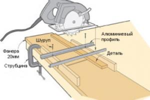
With a desktop engraving and milling machine made of aluminum CNC-2020AL, complete with a control unit with the ability to adjust spindle speed, Figure 1 and 2, the control unit contains a stepper motor driver on a TB6560AHQ chip, power supplies for the stepper motor driver and a spindle power supply.

picture 1

Figure 2
1. One of the first control controllers for CNC milling machines on the TB6560 chip was nicknamed “blue board”, Figure 3. This version of the board was discussed a lot on the forums, it has a number of disadvantages. The first is the slow PC817 optocouplers, which requires, when setting up the MACH3 machine control program, to enter the maximum allowable value in the Step pulse and Dir pulse = 15 fields. The second is poor matching of the optocoupler outputs with the inputs of the TB6560 driver, which can be solved by modifying the circuit, Figure 8 and 9. The third. - linear stabilizers for the board's power supply and, as a result, high overheating; switching stabilizers are used on subsequent boards. The fourth is the lack of galvanic isolation of the power supply circuit. The spindle relay is 5A, which in most cases is not enough and requires the use of a more powerful intermediate relay. The advantages include the presence of a connector for connecting a control panel. This controller is not used.

Figure 3.
2. The CNC machine control controller entered the market after the “blue board”, nicknamed the red board, Figure 4.
Higher frequency (fast) optocouplers 6N137 are used here. Spindle relay 10A. Availability of galvanic isolation for power supply. There is a connector for connecting the fourth axis driver. Convenient connector for connecting limit switches.

Figure 4.
3. The stepper motor controller marked TB6560-v2 is also red, but simplified, there is no power decoupling, Figure 5. Small size, but as a result of this, the size of the radiator is smaller.

Figure 5
4. Controller in aluminum housing, Figure 6. The housing protects the controller from dust and metal parts; it also serves as a good heat sink. Galvanic isolation for power supply. There is a connector for powering additional +5V circuits. Fast optocouplers 6N137. N low-impedance and Low ESR capacitors. There is no relay for controlling the spindle turning on, but there are two outputs for connecting a relay (transistor switches with OK) or PWM for controlling the spindle rotation speed. Description of connecting relay control signals on the page

Figure 6
5. 4-axis controller of a CNC milling and engraving machine, USB interface, Figure 7.

Figure 7
This controller does not work with the MACH3 program; it comes with its own machine control program.
6. CNC controller of the machine on the SD driver from Allegro A3977, Figure 8.

Figure 8
7.Single-channel stepper motor driver for CNC machine DQ542MA. This driver can be used when self-production a machine with a large working field and stepper motors with a current of up to 4.2A, can also work with Nema34 86mm motors, Figure 9.

Figure 9
Photo of the modification of the blue stepper motor controller board on the TB6560, Figure 10.

Figure 10.
Scheme for fixing the blue stepper motor controller board on the TB6560, Figure 11.

Since I assembled a CNC machine for myself a long time ago and have been using it regularly for hobby purposes for a long time, I hope my experience will be useful, as will the source codes of the controller.
I tried to write only those points that I personally found important.
The link to the controller sources and the configured Eclipse+gcc shell, etc. are located in the same place as the video:
History of creation
Regularly faced with the need to make one or another small “thing” of a complex shape, I initially thought about a 3D printer. And he even started doing it. But I read the forums and assessed the speed of the 3D printer, the quality and accuracy of the result, the percentage of defects and the structural properties of thermoplastic, and I realized that this is nothing more than a toy.The order for components from China arrived within a month. And after 2 weeks the machine was working with LinuxCNC control. I assembled it from whatever crap I had at hand, because I wanted to do it quickly (profile + studs). I was going to redo it later, but, as it turned out, the machine turned out to be quite rigid, and the nuts on the studs did not have to be tightened even once. So the design remained unchanged.
Initial operation of the machine showed that:
- Do not use a “china noname” 220V drill as a spindle best idea. It overheats and is terribly loud. The lateral play of the cutter (bearings?) can be felt by hand.
- The Proxon drill is quiet. The play is not noticeable. But it overheats and turns off after 5 minutes.
- A borrowed computer with a bidirectional LPT port is not convenient. Borrowed for a while (finding PCI-LPT turned out to be a problem). Takes up space. And generally speaking..
Why people still stubbornly torment 8-bit ATMega for relatively complex tasks, and even through Arduino, is a mystery to me. They probably love difficulties.
Controller development
I created the program after thoughtfully reviewing the LinuxCNC and gbrl sources. However, I did not take either of the sources for calculating the trajectory. I wanted to try to write a calculation module without using float. Exclusively on 32-bit arithmetic.The result suits me for all operating modes and I haven’t touched the firmware for a long time.
Maximum speed, selected experimentally: X: 2000 mm/min Y: 1600 Z: 700 (1600 step/mm. mode 1/8).
But it is not limited by controller resources. It’s just that the disgusting sound of skipping steps even on straight sections through the air is higher. The budget Chinese stepper control board on the TB6560 is not the best option.
In fact, I don’t set the speed for wood (beech, 5mm depth, d=1mm cutter, step 0.15mm) to more than 1200mm. The likelihood of cutter failure increases.
The result is a controller with the following functionality:
- Connection to an external computer as a standard usb mass storage device (FAT16 on an SD card). Working with standard G-code format files
- Deleting files through the controller user interface.
- View the trajectory of the selected file (as far as the 640x320 screen allows) and calculate the execution time. In fact, emulation of execution with time summation.
- View the contents of files in test form.
- Mode manual control from the keyboard (moving and setting “0”).
- Start execution of a task using the selected file (G-code).
- Pause/resume execution. (sometimes useful).
- Emergency software stop.
After creative experiments in cutting out hand-drawn reliefs on wood, and experiments with acceleration settings in the program, I also wanted additional encoders on the axes. Just on e-bay I found relatively cheap optical ecocoders (1/512), the division pitch of which for my ball screws was 5/512 = 0.0098 mm.
By the way, using high-resolution optical encoders without a hardware circuit for working with them (the STM32 has one) is pointless. Neither interrupt processing, nor, especially, software polling will ever cope with the “bounce” (I’m saying this for ATMega fans).
First of all, I wanted for the following tasks:
- Manual positioning on the table with high precision.
- Control of missed steps with control of deviation of the trajectory from the calculated one.
However, I found another use for them, albeit in a rather narrow task.
Using encoders to correct the trajectory of a machine with stepper motors
I noticed that when cutting out a relief, when setting the Z acceleration to more than a certain value, the Z axis begins to slowly but surely creep down. But, the time for cutting relief with this acceleration is 20% less. Upon completion of cutting out a 17x20 cm relief with a step of 0.1 mm, the cutter can go down 1-2 mm from the calculated trajectory.
Analysis of the situation in dynamics using encoders showed that when lifting the cutter, 1-2 steps are sometimes lost.
A simple step correction algorithm using an encoder gives a deviation of no more than 0.03 mm and reduces processing time by 20%. And even a 0.1 mm protrusion on wood is difficult to notice.
Design

I considered it an ideal option for hobby purposes. desktop version with a field slightly larger than A4. And this is still enough for me.
Movable table
It still remains a mystery to me why everyone chooses a design with a movable portal for tabletop machines. Its only advantage is the ability to process a very long board in parts or, if you have to regularly process material that weighs more than the weight of the portal.During the entire period of operation, there was never a need to cut out a relief piece by piece on a 3-meter board or engrave on a stone slab.
The movable table has the following advantages for tabletop machines:
- The design is simpler and general case, the structure is more rigid.
- All the internals (power supplies, boards, etc.) are hung on a fixed portal and the machine turns out to be more compact and more convenient to carry.
- The weight of the table and a piece of typical material for processing is significantly lower than the weight of the portal and spindle.
- The problem with cables and spindle water cooling hoses practically disappears.
Spindle
I would like to note that this machine is not for power processing. The easiest way to make a CNC machine for power processing is on the basis of a conventional milling machine.In my opinion, a machine for power processing of metal and a machine with a high-speed spindle for processing wood/plastics are absolutely different types equipment.
Create conditions at home universal machine at least it makes no sense.
The choice of a spindle for a machine with this type of ball screw and guides with linear bearings is straightforward. This is a high speed spindle.
For a typical high-speed spindle (20,000 rpm), milling non-ferrous metals (steel is out of the question) is an extreme mode for the spindle. Well, unless it’s really necessary and then I’ll eat 0.3 mm per pass with watering the coolant.
I would recommend a water-cooled spindle for the machine. During operation, you can only hear the “singing” of the stepper motors and the gurgling of the aquarium pump in the cooling circuit.
What can be done on such a machine?
First of all, I got rid of the housing problem. The body of any shape is milled from “plexiglass” and glued together with a solvent along ideally smooth cuts.
Fiberglass has become a universal material. The precision of the machine allows you to cut seat under the bearing, into which it will go cold, as it should be, with a slight tension, and then you can’t pull it out. Textolite gears are perfectly cut with an honest involute profile.
Wood processing (reliefs, etc.) is a wide scope for the realization of one’s creative impulses, or, at a minimum, for the realization of other people’s impulses (ready-made models).
I just haven’t tried the jewelry. There is nowhere to calcinate/melt/cast the flasks. Although a block of jewelry wax is waiting in the wings.
This is my first CNC machine assembled with my own hands from available materials. The cost of the machine is about $170.
I have been dreaming of assembling a CNC machine for a long time. I mainly need it for cutting plywood and plastic, cutting some parts for modeling, homemade products and other machines. My hands itched to assemble the machine for almost two years, during which time I collected parts, electronics and knowledge.
The machine is budget, its cost is minimal. In what follows I will use words that to an ordinary person may seem very scary and this can scare away self-built machine, but in fact it’s all very simple and easy to master in a few days.
Electronics assembled on Arduino + GRBL firmware
The mechanics are the simplest, a frame made of 10mm plywood + 8mm screws and bolts, linear guides made of a metal angle 25*25*3 mm + bearings 8*7*22 mm. The Z axis moves on an M8 stud, and the X and Y axes on T2.5 belts.
The CNC spindle is homemade, assembled from a brushless motor and collet clamp+ toothed belt drive. It should be noted that the spindle motor is powered from the main 24 volt power supply. IN technical specifications The motor is stated to be 80 amps, but in reality it consumes 4 amps under heavy load. I can’t explain why this happens, but the motor works great and does its job.

Initially, the Z axis was on homemade linear guides made from angles and bearings, later I remade it, photos and description below.

The working space is approximately 45 cm in X and 33 cm in Y, 4 cm in Z. Taking into account the first experience, I will make the next machine with larger dimensions and will install two motors on the X axis, one on each side. This is due to the large arm and the load on it, when work is carried out at the maximum distance along the Y axis. Now there is only one motor and this leads to distortion of the parts, the circle turns out to be a bit elliptical due to the resulting flexion of the carriage along the X.

The original bearings on the motor quickly became loose because they were not designed for lateral load, and this is serious. Therefore, I installed two on the top and bottom of the axle large bearing with a diameter of 8 mm, this should have been done right away, now there is vibration because of this.

Here in the photo you can see that the Z axis is already on other linear guides, the description will be below.


The guides themselves are very simple design, I somehow accidentally found it on Youtube. Then this design seemed ideal to me from all sides, minimum effort, minimum details, easy assembly. But as practice has shown, these guides do not work for long. The photo shows the groove that formed on the Z axis after a week of my test runs of the CNC machine.

I replaced the homemade guides on the Z axis with furniture ones; they cost less than a dollar for two pieces. I shortened them, leaving a stroke of 8 cm. There are still old guides on the X and Y axes, I won’t change them for now, I plan to cut out parts for a new machine on this machine, then I’ll just disassemble this one.


A few words about cutters. I have never worked with CNC and I also have very little milling experience. I bought several cutters in China, all of them have 3 and 4 grooves, later I realized that these cutters are good for metal, but for milling plywood you need other cutters. While new cutters cover the distance from China to Belarus, I am trying to work with what I have.
The photo shows how a 4 mm cutter burned on 10 mm birch plywood, I still didn’t understand why, the plywood was clean, but on the cutter there was carbon deposits similar to pine resin.

Next in the photo is a 2 mm four-flute cutter after an attempt to mill plastic. This piece of melted plastic was then very difficult to remove; I had to bite it off a little bit with pliers. Even at low speeds the cutter still gets stuck, 4 grooves are clearly for metal :)

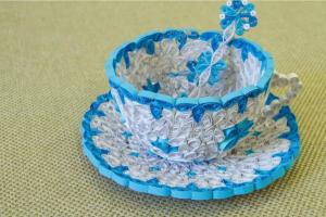
The other day it was my uncle's birthday, on this occasion I decided to make a gift on my toy :)
As a gift, I made a full house for a plywood house. First of all, I tried milling on foam plastic to test the program and not spoil the plywood.


Due to backlash and bending, the horseshoe could only be cut out the seventh time.


In total, this full house (in its pure form) took about 5 hours to mill + a lot of time for what was spoiled.

I once published an article about a key holder, below in the photo is the same key holder, but already cut on a CNC machine. Minimum effort, maximum precision. Due to the backlash, the accuracy is certainly not maximum, but I will make the second machine more rigid.


I also used a CNC machine to cut gears out of plywood; it’s much more convenient and faster than cutting it with my own hands with a jigsaw.
Later I cut out square gears from plywood, they actually spin :)
The results are positive. Now I’ll start developing a new machine, I’ll cut out parts on this machine, manual labor practically comes down to assembly.
You need to master cutting plastic, because you are working on a homemade robot vacuum cleaner. Actually, the robot also pushed me to create my own CNC. For the robot I will cut gears and other parts from plastic.
Update: Now I buy straight cutters with two edges (3.175 * 2.0 * 12 mm), they cut without severe scoring on both sides of the plywood.
The article describes homemade machine with CNC. Main advantage this option machine tool - a simple method of connecting stepper motors to a computer via the LPT port.
Mechanical part
bed
The bed of our machine is made of plastic with a thickness of 11-12mm. The material is not critical, you can use aluminum, organic glass, plywood and any other available material. The main parts of the frame are attached using self-tapping screws; if desired, you can additionally decorate the fastening points with glue; if you use wood, you can use PVA glue.
Calipers and guides
Steel rods with a diameter of 12mm, length 200mm (Z axis 90mm), two pieces per axis, were used as guides. The calipers are made of textolite with dimensions 25X100X45. Textolite has three through holes, two of them for the guides and one for the nut. The guide parts are fastened with M6 screws. The X and Y supports have 4 threaded holes at the top for attaching the table and Z axis assembly.

Caliper Z
The Z axis guides are attached to the X support through a steel plate, which is a transition plate, the dimensions of the plate are 45x100x4.


Stepper motors are mounted on fasteners, which can be made of sheet steel with a thickness of 2-3mm. The screw must be connected to the axis of the stepper motor using a flexible shaft, which can be a rubber hose. If you use a rigid shaft, the system will not work accurately. The nut is made of brass, which is glued into the caliper.

Assembly
Assembly homemade CNC machine, is carried out in the following sequence:
- First you need to install all the guide components in the calipers and screw them to the sidewalls, which are not first installed on the base.
- We move the caliper along the guides until we achieve smooth movement.
- Tighten the bolts, fixing the guide parts.
- We attach the caliper, guide assembly and side frame to the base; we use self-tapping screws for fastening.
- We assemble assembly Z and, together with the adapter plate, attach it to support X.
- Next we install lead screws along with couplings.
- We install stepper motors by connecting the motor rotor and the screw with a coupling. We pay strict attention to ensure that the lead screws rotate smoothly.
Recommendations for assembling the machine:
Nuts can also be made from cast iron; there is no need to use other materials; screws can be purchased at any hardware store and trim to suit your needs. When using screws with M6x1 thread, the nut length will be 10 mm.
Machine drawings.rar
Let's move on to the second part of assembling a CNC machine with our own hands, namely the electronics.
Electronics
power unit
A 12Volt 3A unit was used as a power source. The block is designed to power stepper motors. Another voltage source of 5 Volts and a current of 0.3 A was used to power the controller microcircuits. The power supply depends on the power of the stepper motors.
Here is the calculation of the power supply. The calculation is simple - 3x2x1=6A, where 3 is the number of stepper motors used, 2 is the number of powered windings, 1 is the current in Amperes.

Controller
The control controller was assembled using only 3 555TM7 series microcircuits. The controller does not require firmware and has a fairly simple schematic diagram, thanks to this, this CNC machine can be made by a person who is not particularly versed in electronics.

Description and purpose of the LPT port connector pins.
| Vvyv. | Name | Direction | Description |
| 1 | STROBE | input and output | Sets the PC after each data transfer is completed |
| 2..9 | DO-D7 | conclusion | Conclusion |
| 10 | ASK | input | Set to “0” by an external device after receiving a byte |
| 11 | BUSY | input | The device indicates that it is busy by setting this line to "1" |
| 12 | Paper out | input | For printers |
| 13 | Select | input | The device indicates that it is ready by setting this line to "1" |
| 14 | Autofeed | ||
| 15 | Error | input | Indicates an error |
| 16 | Initialize | input and output | |
| 17 | Select In | input and output | |
| 18..25 | Ground GND | GND | Common wire |
For the experiment, a stepper motor from an old 5.25-inch was used. In the circuit, 7 bits are not used because 3 engines are used. You can hang the key to turn on the main engine (mill or drill) on it.
Driver for stepper motors
To control the stepper motor, a driver is used, which is an amplifier with 4 channels. The design is implemented using only 4 transistors of the KT917 type.

You can also use serial microcircuits, for example - ULN 2004 (9 keys) with a current of 0.5-0.6A.

The vri-cnc program is used for control. Detailed description and instructions for using the program are located at.


By assembling this CNC machine with your own hands, you will become the owner of a machine capable of performing mechanical processing (drilling, milling) of plastics. Engraving on steel. Also, a homemade CNC machine can be used as a plotter; you can draw and drill printed circuit boards on it.


Based on materials from the site: vri-cnc.ru