Among the various devices created for pumping all kinds of liquids, the centrifugal pump turned out to be the most practical: the operating principle of this unit provides a combination high performance and good pressure, but at the same time allows you to make the design extremely simple.
Most household pumps and pumping stations used for irrigation summer cottages and organizations autonomous water supply in private homes belong precisely to this type.
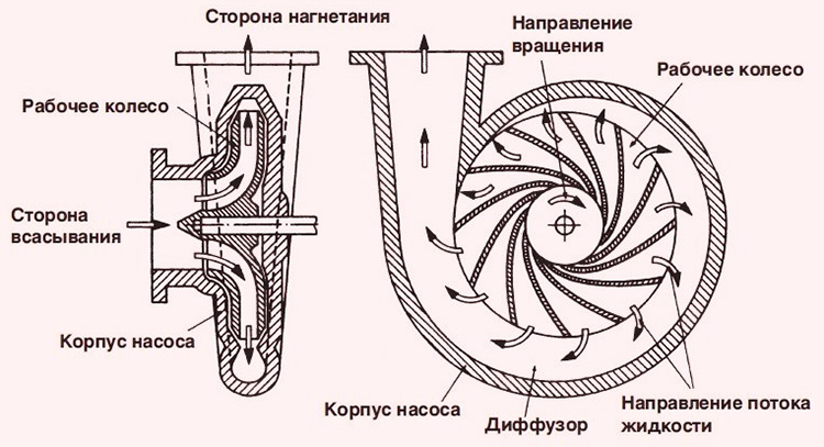
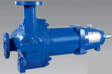
![]() The working part of a centrifugal pump in its simplest design consists of a housing that looks a little like a spiral or volute, a shaft located inside it and an impeller mounted on this shaft.
The working part of a centrifugal pump in its simplest design consists of a housing that looks a little like a spiral or volute, a shaft located inside it and an impeller mounted on this shaft.
The transmission of rotation from the shaft to the wheel is carried out by means of a key.
The impeller consists of two disks and several blades fixed between them. The blades have a curved shape and are turned with the convex side in the direction of rotation.
The pump body is made of steel or cast iron; the impellers in many models, especially those intended for domestic water supply, are made of polymers.
The impeller shaft can be either double-supported or cantilever. Bearings are installed in the support units.
The shaft shank comes out of the housing and is connected through a coupling to the rotor of an electric engine or the crankshaft of a diesel engine, which acts as a drive.
The hole in the pump body through which the shaft shank passes has a seal that prevents leakage of the pumped substance.
When choosing a centrifugal pump, it is better to give preference to models with a mechanical shaft seal. It is more reliable than stuffing box packing, which is considered obsolete. In addition, the mechanical seal will be able to ensure the tightness of the housing even when the impeller shaft is displaced or vibrations occur.
![]()
Centrifugal pump device
Water or other media enters the working chamber of the pump through an opening in the center of the front part of the housing. Its injection is carried out through a smooth outlet in the upper part, which gives the body a resemblance to a snail.
In addition to the main parts (housing and drive), which actually constitute the pump, the delivery set includes elements without which operation of the unit would be difficult or even impossible:
- mesh filter;
- check valve for the suction line;
- valve (installed in front of the suction pipe);
- vacuum gauge (allows you to control the degree of vacuum at the entrance to the working chamber).
If the purchased pump is intended to be used to supply drinking water, you must ensure that all parts in contact with it are made of appropriate materials. In this case, the body must be made of high quality of stainless steel, the impeller is also made of stainless steel or food-grade plastic.
Quite popular are models with a body made of ordinary, “non-food” material, inside of which a stainless steel liner is installed.
Such a unit will cost less than a completely stainless one. Repairing it will also cost less: instead of restoring the body, it will be enough to replace the worn liner.
Operating principle
After the drive motor starts, the pump shaft with the wheel mounted on it begins to rotate. The wheel blades also cause the substance in the working chamber to rotate.
As soon as the fluid begins to move in a circle, it is subjected to centrifugal force directed from the center. Moreover, the greater the modulus of this force, the further the molecules of the pumped medium are displaced from the center of rotation.
Operating principle of a centrifugal pump
Eventually the liquid is discharged to the periphery of the impeller and then into the upward curved outlet pipe. Thus, the pressure or, as they also say, pressure in the discharge line is maintained due to centrifugal force.
Classification
Pumps of this type can be classified according to a number of characteristics.
By number of steps
- Single stage: have only one impeller. This design, considered classic, has been described in detail above.
- Multistage: such pumps are used when it is necessary to develop significant pressure. They have several impellers mounted on a common shaft. The operating principle of a multistage centrifugal pump: each wheel, together with its working chamber, forms a stage. The pump housing is designed in such a way that water or other liquid sequentially passes from one stage to another until it reaches the outlet pipe. In this case, the pressure with which it is supplied is equal to the sum of the pressures developed by each stage.
In the direction of the axis of rotation
- With a horizontal shaft: the most popular type due to ease of maintenance.
- WITH vertical arrangement shaft: such pumps require less space for installation, since the engine is located above the body. The majority belong to this type borehole pumps who have to work in rather cramped conditions. The disadvantage of this design is that the engine often has to be removed to repair or service the housing.
 To provide autonomous water supply most often purchased submersible pumps. When choosing a unit, it is important to take into account safety parameters. In this plan the best option will . Automation will provide protection against dry running and voltage surges, which will guarantee long-term operation of the equipment.
Why are pumps needed to increase water pressure, read.
If you need to deliver water from a well to your home for drinking or for watering your garden, then the Rucheek pump is suitable for you. Although it is not very powerful, it will cope with such minimal functions, and you will benefit from the price. Here you will learn everything about the characteristics and operation of the pump.
By installation method
- Surface: located near the source or at some distance from it. They are the cheapest, are constantly in sight, and are easily accessible for visual inspection and maintenance. Disadvantage: the water level in the source must be at least 8 m relative to the pump installation level, therefore such units cannot work with deep wells or boreholes.
- Semi-submersible: pumps with a vertical shaft. They are installed so that part of the body is immersed in the source. Most often they are used for pumping out liquid substances from pits.
- Submersible: in deep wells and boreholes, pumps are used that, being suspended on a cable or chain, are completely immersed in water.
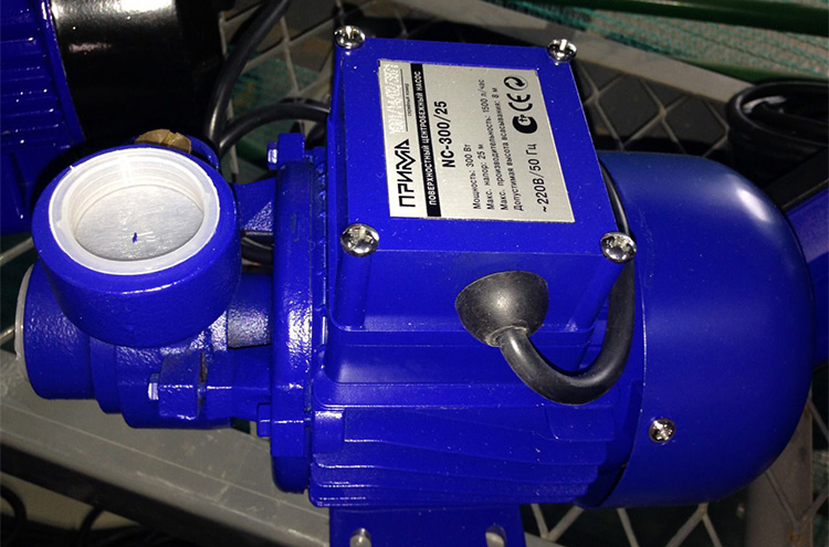
Domestic surface centrifugal pump
In order for the latter method of operation to be possible, the unit must meet several requirements:
- all external elements must be resistant to corrosion;
- Not only the housing, but also the electrical part must be sealed;
- The design of the pump and the quality of assembly must completely eliminate leaks of machine oil, the removal of which from a well or well is very expensive.
It is clear that under such conditions a submersible pump is more expensive than a surface pump, but it is impossible to lift water from great depths in any other way.
For owners of shallow wells (up to 25 - 30 m), we can recommend a compromise option that combines the advantages of surface and submersible models.
We are talking about pumps with a remote ejector. The pump itself is installed at the top, which is very convenient, and its part - the ejector - is lowered into the well to a great depth.
By method of water intake
- Normal suction pumps: This type includes all submersible pumps, as well as some surface ones, into which water flows by gravity (for example, when pumping water from a tank with a tap located below). Before the first start-up, the cavity of the unit must be filled with water; in the future, you no longer have to worry about this.
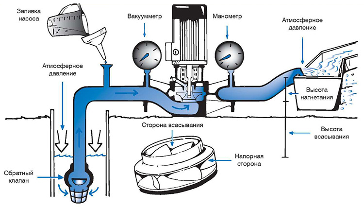
- Self-priming: this is the name given to pumps that can lift water from a certain depth. Theoretically, it is 10.34 m, but in practice it does not exceed 8 m. The self-priming pump must be primed every time after a relatively long period of inactivity, and not only the cavity of the unit, but also the suction hose must be filled with water. The latter must have reinforcement that prevents its compression due to vacuum.
Self-priming water pump - operating principle
Launch self-priming pump and its operation in intermittent mode would be impossible without the most important element - check valve on the suction line. During pouring and during short pauses in the operation of the unit, it retains water, preventing rupture of the water column.
Not all household pumping stations have this mechanism included. Thus, a tempting offer with a price “lower than others” may turn out to be a catch.
According to the location of the inlet and outlet pipes
- Classic: the suction and supply pipes are located as described above: the first is in the front (center), the second is on top.
- In-Line pumps: differ from conventional models in that both pipes (suction and supply) are located on the same axis.
For pumping toxic, chemically aggressive and other hazardous substances Another type is used - sealed centrifugal pumps. They are designed in such a way that leakage of the pumped substance becomes absolutely impossible.
There are two types of execution:
- The motor is located inside the housing, and the impeller is mounted on its shaft.
- The engine and the absolutely sealed housing are made separately, and torque is transmitted to the impeller via a magnetic coupling.
Characteristics of centrifugal pumps
 The operating parameters of the pumps are:
- power consumption (W);
- productivity (cubic m/h or l/min);
- outlet pressure, usually referred to as pressure (measured in meters of water column, abbreviated as m.w.c.).
The peculiarity of centrifugal pumps is that their performance depends on the pressure.
How greater pressure the unit has to be developed to lift water to a greater height or “push it” through a long pipeline with high hydraulic resistance, the smaller the volume of water it can pump per unit of time.
The basic equation of a centrifugal pump is for the first time general view was obtained in 1754 by L. Euler and bears her name.
Considering the movement of liquid inside the impeller, we will make the following assumptions: the pump pumps ideal liquid in the form of jets, i.e., there are no types of energy losses in the pump. The number of identical pump blades is infinitely large (z = µ), their thickness is zero (d = 0), and the angular speed of rotation of the wheel is constant (w = const.).
Liquid is supplied axially to the impeller of a centrifugal pump at a speed Vo, i.e. in the direction of the shaft axis. Then the direction of the liquid jets changes from axial to radial, perpendicular to the shaft axis, and the speed due to centrifugal force increases from the value V1 in the space between the blades of the impeller to the value V2 at the exit of the wheel.
In the inter-blade space of the impeller, when the fluid moves, absolute and relative flow velocities are distinguished. Relative speed flow - speed relative to the impeller, and absolute - relative to the pump housing.
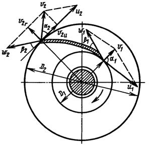
Rice. Diagram of fluid movement in the impeller of a centrifugal pump
The absolute speed is equal to the geometric sum of the relative fluid speed and the peripheral speed of the impeller. The peripheral speed of the fluid exiting between the impeller blades coincides with the peripheral speed of the wheel at a given point.
Peripheral fluid velocity (m/s) at the impeller inlet
Peripheral speed of liquid at the outlet of the impeller (m/s)
Where n-impeller rotation speed, rpm; D1 And D2- internal and external diameters of the impeller, m, w- angular speed of rotation of the impeller rad/s
When the impeller moves, fluid particles move along the blades. Rotating together with the impeller, they acquire a peripheral speed, and moving along the blades - a relative speed.
The absolute speed v of the fluid movement is equal to the geometric sum of its components: the relative speed w and district u, i.e. v = w + i.
The relationship between the velocities of liquid particles is expressed by a parallelogram or triangles of velocities, which makes it possible to give an idea of the radial and circumferential components of absolute velocity.
Radial component
![]()
circumferential component
![]()
where a is the angle between the absolute and peripheral speeds (at the impeller inlet a1 and at the outlet a2).
The angle b between the relative and peripheral speeds characterizes the outline of the pump blades.
We study the change in 1 since the moment of momentum of the mass of the liquid t = rQ, Where r- liquid density; Q- pump supply.
Using the theorem of mechanics on the change in angular momentum in relation to the movement of liquid in the channel of the impeller, we will derive the basic equation of a centrifugal pump, which will allow us to determine the pressure (or pressure) developed by the pump. This theorem states: the change in time of the main angular momentum of a system of material points relative to a certain axis is equal to the sum of the moments of all forces acting on this system.
The moment of momentum of the fluid relative to the axis of the impeller in the inlet section
![]()
Moment of momentum at the impeller exit
![]()
where r1 and r2 - distances from the wheel axis to the input V1 and output V2 speed vectors, respectively.
According to the definition of the moment of the system, we can write:
Since according to Fig.
![]()
![]()
Groups of external forces - gravity, pressure forces in the design sections (inlet-outlet) and on the side of the impeller and fluid friction forces on the streamlined surfaces of the impeller blades - act on the mass of liquid filling the inter-blade channels of the impeller.
The moment of gravity forces relative to the axis of rotation is always equal to zero, since the leverage of these forces is equal to zero. For the same reason, the moment of pressure forces in the design sections is also equal to zero. If the friction forces are neglected, then the moment of the friction forces is zero. Then the moment of all external forces relative to the axis of rotation of the wheel is reduced to the moment Mk the dynamic effect of the impeller on the fluid flowing through it, i.e.
![]()
Work Mk by relative speed is equal to the product of flow rate and theoretical pressure PT, created by the pump, i.e. equal to the power transmitted to the fluid by the impeller. Hence,
![]()
This equation can be represented as
Dividing both parts into Q, we get
Considering that pressure N = P/(pg) and substituting this value we get
If we neglect friction forces, we can obtain dependencies called basic equations of a vane pump. These equations reflect the dependence of the theoretical pressure or head on the main parameters of the impeller. The transfer speeds at the entrance to the axial pump and at the exit from it are the same, so the equation takes the form
![]()
In most pumps, liquid enters the impeller almost radially and, therefore, the speed V1 » 0. Taking into account the above
 or
or ![]()
The theoretical pressure and pressure developed by the pump, the greater, the greater the peripheral speed on the outer circumference of the impeller, i.e., the larger its diameter, rotation speed and angle b2, i.e., the “steeper” the impeller blades are located.
The actual pressure and pressure developed by the pump are less than the theoretical ones, since the actual operating conditions of the pump differ from the ideal ones accepted when deriving the equation. The pressure developed by the pump decreases mainly due to the fact that with a finite number of impeller blades, not all fluid particles are deflected uniformly, as a result of which the absolute speed decreases. In addition, part of the energy is spent on overcoming hydraulic resistance. The influence of the finite number of blades is taken into account by introducing a correction factor k(characterizing a decrease in the circumferential velocity component V2u), a decrease in pressure due to hydraulic losses - by introducing a hydraulic coefficient useful action hr. Taking these corrections into account, the total pressure
 and full pressure
Coefficient value hr depends on the design of the pump, its size and quality of workmanship internal surfaces wheel flow part. Usually the value hr is 0.8...0.95. Meaning k with the number of blades from 6 to 10, a2 = 8...14 0 and V2u = 1.5...4 m/s, it ranges from 0.75 to 0.9.
When the impeller of a centrifugal pump rotates, the liquid located between the blades, thanks to the developed centrifugal force, is thrown through the volute chamber into the pressure pipeline. The escaping liquid frees up the space it occupies in the channels on the inner circumference of the impeller, so a vacuum is formed at the entrance to the impeller, and at the periphery - overpressure. Under the influence of the difference in atmospheric pressure in the receiving tank and the reduced pressure at the inlet to the impeller, the liquid flows through the suction water supply into the inter-blade channels of the impeller.
A centrifugal pump can only operate if its internal cavity is filled with the pumped liquid not lower than the pump axis, therefore pumping unit equipped with a device for priming the pump.
The liquid is supplied to the impeller of a centrifugal pump axially, i.e. in the direction of the shaft axis, at a speed v. In the impeller, the direction of the liquid jets changes from axial to radial, perpendicular to the shaft axis (Fig. 2.7).
The liquid enters the channels of the impeller (i.e., into the space between the blades) at a speed v 1, which increases in the channels and reaches the value v 2 at the exit from the impeller (we will use the index “1” to denote the speeds and angles at the entrance to the impeller, and index “2” - at the exit from it).
Moving along the channel of the impeller, the liquid particles undergo a complex movement: rotational - together with the wheel at a peripheral speed and translational - relative to the surfaces of the blades at a speed w. The relative speed is directed tangent to the surface of the blade at a given point, and the peripheral speed u is directed tangent to the circle on which this point lies. At the exit from the impeller, the peripheral speed is u2=π*D2n, where D2 is the diameter of the impeller, m; n - wheel rotation speed, s -1.
For simplicity of mathematical generalizations, we further assume that the fluid motion in the impeller is a jet and the trajectories of each moving particle coincide with the outline of the blade. As a result of the conclusions obtained on the basis of such an assumption, it will be necessary in the future to make adjustments (coefficients) that take into account the actual movement of the fluid.
The absolute velocity of the fluid v is equal to the geometric sum of its components v = w+u.
Let us also introduce the concept of the radial and circumferential components of the absolute velocity v. Radial component of absolute speed (meridional speed) vr=v sin a,
where a is the angle between the absolute speed v and the tangent to the circle at the point where the fluid particle leaves the blade (or enters it).
Circumferential component of absolute speed vu = v cos a.
For further conclusions, we also introduce the concept of angle β - the angle between the relative speed w and the tangent to the circle at the point of departure of a fluid particle from the blade (or entry to it).
The basic equation of a centrifugal pump, which allows us to determine the power it develops pressure or pressure, can be derived using the theorem on the change in angular momentum, which is formulated as follows: the change in time of the main angular momentum of a system of material points relative to a certain axis is equal to the sum of the moments of all forces acting on this system.
Applying this theorem to the movement of liquid through a pump impeller, let us assume that this movement is steady, jet, without hydraulic losses. Let us consider the change in the angular momentum of a liquid mass over 1 s. In this case, the mass of the fluid involved in the movement will be m = pQ (p is the density of the fluid, Q is the pump flow).
The moment of momentum relative to the axis of the impeller in the inlet section at the speed of movement in this section v 1: M 1 =pQv 1 r 1.
Moment of momentum at the exit from the impeller: M 2 =pQv 2 r 2 , where r 1 and r 2 are the distances from the wheel axis to the input and output speed vectors, respectively.
Sum of moments of forces:
![]()
Since, in accordance with Fig. 2.7
That
The mass of liquid filling the inter-blade channels of the impeller is affected by three groups of external forces: gravity, pressure forces in the design sections (inlet - outlet) and from the impeller, and fluid friction forces on streamlined surfaces.
The moment of gravity is always zero, since the arm of these forces is zero (they pass through the axis of rotation of the wheel). For the same reason, the moment of pressure forces in the design sections is also equal to zero. Since the friction forces are neglected, the moment of the friction forces is equal to zero. Consequently, the moment of all external forces relative to the axis of rotation of the wheel is reduced to the moment Mk of the dynamic action of the impeller on the fluid flowing through it, i.e.
The power transmitted to the fluid by the impeller, i.e., the product of Mk and the relative speed, is equal to the product of the flow rate and the theoretical pressure RT created by the pump. Hence.
Taking into account expressions (2.6) and (2.7), equation (2.5) can be represented as
The portable speeds of movement in the sections under consideration at the entrance to the wheel and exit from it are respectively equal
![]()
Substituting their values into equation (2.8) and dividing both sides by O, we obtain
As is known from hydraulics, pressure H = p/pg or p = pgH. Substituting this value into equation (2.9), we obtain
Dependencies (2.9) and (2.10) are called the basic equations of a vane pump. Equations (2.9) and (2.10) are derived from the condition of neglecting friction forces, therefore they reflect the dependence of the theoretical pressure or head developed by the pump on the main parameters of the impeller.
For axial pumps, due to the fact that the transfer speeds at the inlet and outlet are the same, equation (2.9) takes the form
The liquid enters the impeller of most pumps practically radially (a1=0°, therefore, u1=0), so equations (2.9) and (2.10) are simplified and take the form:
![]()
The basic equations of a centrifugal pump show that the theoretical pressure and head developed by the pump are the greater, the greater the peripheral speed on the outer circumference of the impeller, i.e., the greater its diameter, speed and angle b2 (see Fig. 2.7), i.e., the “steeper” the impeller blades are located.
The actual pressure and pressure developed by the pump are less than the theoretical ones, since the actual operating conditions of the pump differ from the ideal ones accepted when deriving the equation. The pressure developed by the pump decreases mainly due to the fact that with a finite number of impeller blades, not all fluid particles are deflected uniformly, as a result of which the absolute speed decreases. In addition, part of the energy is spent on overcoming hydraulic resistance. The influence of a finite number of blades is taken into account by introducing a correction factor k, which characterizes the decrease in the value of v2u. The decrease in pressure due to hydraulic losses is taken into account by introducing a hydraulic efficiency coefficient.
Taking these corrections into account, the total pressure is:
full head:
The value of the coefficient n depends on the design of the pump, its dimensions and the quality of the internal surfaces of the wheel flow part. Typically, the value of n is in the range of 0.8–0.95. The value of k with the number of blades from 6 to 10, a2 = 8/14° and v2u = 1.5/4 m/s ranges from 0.75 to 0.9.


