Most often used by car enthusiasts to press out and replace the driveshaft crosspiece. This procedure can be carried out using a hammer, but then you can damage both the cardan and the cross itself. Therefore, we will consider how to dismantle the crosspiece in a more humane and in a simple way using this device.
What is a crosspiece puller and why is it needed?
Puller for cardan shaft crosspieces is a tool that is used to dismantle various parts and assemblies (pulleys, gears, bushings, wheels, couplings, bearings) that have an interference fit. This tool consists of two support plates, two ties, two nuts, two pieces of pipe and a bolt. As a rule, it is made of structural steel.
The cardan shaft crosspiece remover can be used without extra effort remove the bearings from their forks without damaging adjacent parts. The puller can also act as a device for repairing a universal joint, since universal joints serve an average of 70-80 thousand km, during which time they wear out sufficiently and require replacement. In this case, the puller helps to extend the working life. In this case, you need to know that the spikes of the cross wear out more intensively only on one side. Therefore, when removing the hinge, it is necessary to make appropriate notes, wash and lubricate its parts, and then reassemble and install it, while rotating the cross 180°C around one of the axes relative to the previous position, in this case the main load during operation will fall on less worn side. As a result, such a hinge will last for more than one thousand kilometers.

Types of pullers
Pullers of certain designs can be used for different tasks and specific situations. Therefore, in order to figure out which crosspiece puller is best to use, you need to understand its types and purpose.
There are several types of pullers:
1.Hydraulic– they are designed for dismantling various parts and assemblies (pulleys, gears, bushings) that have an interference fit. In this category, devices with the following types of design are most often used:
- two-grip (for working in confined spaces);
- three-grip (to create a reliable grip).
2.Mechanical used for dismantling parts that are installed with interference, in the case when little effort is required to remove them. The puller jaw locking mechanism allows you to adjust or change the gripping points by simply rotating the locking nut.
3."Clamps", are used for dismantling gears, bearings, wheels, couplings, impellers, pulleys and other press-fitted parts that can be damaged when removed with conventional pullers. The design of the clamp provides a secure grip only when the shape of the part does not allow the use of a conventional puller.
4.Universal crosspiece puller- designed for dismantling parts installed with tension, such as gears, wheels, couplings, impellers, as well as thin-walled parts installed in holes (clips, bearings), which can be damaged when removed with conventional pullers. The Universal Puller is a unique combination of a clamp puller, a combined (external/internal) grip puller and a hollow rod jack that can be removed and used separately.
Since these are the best-selling pullers, let’s consider their types:
- Universal crosspiece puller JTC-5571 (cost RUB 7,800)
- Crosspiece puller Universal Autom 11210 (cost 760-1000 rub.)
- Crosspiece puller Universal Autom-2 (price 800 rub.)
There are also puller designs for internal and external gripping of the part. The cost of crosspiece pullers of all types varies from 500-7900 rubles. In the video presented, you can familiarize yourself with how to use the puller.

Using a puller to remove and install the driveshaft spider
How to use the puller
As mentioned earlier, the puller can be used to replace the driveshaft spider. Therefore, next we will consider in more detail the stages of removing the cross.
Step-by-step instructions for removing the cross:
- After removing the driveshaft, it is necessary to clean the joints from dirt.
- Then, on one side of the cardan, marks are applied that indicate the relative position of the cardan joints; these actions are primarily necessary in order to avoid violations.
- The next step to remove the cross will be to disassemble the universal joint.
- Using snap ring pliers, you need to remove the four corresponding rings.
- If you take into account the installation of bearings in the joint forks with interference, there is a possibility that the forks will be damaged when disassembling the cardan, especially due to corrosion. In this case, experts recommend treating the entire propeller shaft joint with a special penetrating lubricant in advance, and when dismantling the crosspieces, use a special puller instead of a hammer.
- With the help of a puller, the bearings are partially pressed into the tool cup, until the crosspiece does not rest against the fork, although the bearing itself comes out of the fork only 1/3 of its own height.
- In order not to deform the pipe, the driveshaft joint fork is clamped in a vice, and then blows with a hammer are applied to the eyes of the front shaft fork through a drift, causing the crosspiece to move all the way into the fork.
- Next, two half rings are made from a section of pipe, which are installed on the crosspiece tenon, immediately after the front cardan fork (along with it) has been moved in the opposite direction.
- After that, using a puller, the bearing is pressed out of the cardan fork, then the crosspiece is removed from the rear propeller shaft fork.
- In the same way, the bearing is removed from the front shaft fork, having first carefully clamped it in a vice, after which it is already possible to remove the crosspiece.
It is also worth paying attention that before replacing the crosspiece, you need to carefully prepare the universal joint eyes. To do this, they need to be cleaned of dirt and rust. The grooves of the retaining rings are cleaned in a similar way.
This instruction will help motorists not only save money, but also gain the necessary skills for work. Because today the cost of car repair services is too high, and not everyone can afford to have their car serviced at a car service center. Having such a device as a cardan shaft crosspiece remover will make it much easier to cope with the procedure of replacing the crosspiece or repairing the cardan shaft itself.
But if you don’t have such a thing in your garage, but have some enthusiasm, you can even make such a puller with your own hands, saving 500 rubles on purchasing a store-bought version.
How to make a crosspiece remover yourself

If the cross fits with an interference fit of 0.005-0.038 mm, then it can no longer be disassembled by impact without damaging the parts. In this case, pressing out will be necessary, but if the parts have been subjected to corrosion, then this process will be quite complicated. To make the task of replacing the cross easier, you can not only buy such a device, but also make it yourself.
In order to make a device for pressing out cardan shaft crosspieces, you will need to cut a bracket from sheet metal 16 mm thick, and then weld nuts with M22 threads to it (you can order it from a turner). Also for production you need a threaded screw, a knob and knob nuts. Other parts, such as the power screw and threaded parts, can be machined from durable steel. Although this will turn out to be a completely store-bought version of the crosspiece remover. There are simpler ways to do it - just use two strong bolts and weld the nuts to the plate.
Using the device, you need to gradually unscrew screw 1, and while tightening screw 5, gradually press the bearing into the hinge fork. And when the bearing, gradually moving in the eye hole, releases the groove of the retaining ring, then pressing should be stopped and the marked retaining ring should be installed in the groove. Next, pressing the crosspiece against the already pressed bearing, you should turn the hinge fork 180 degrees. In the same way we press in the second bearing and repeat this work twice more on the other universal joint fork.

There is also another manufacturing method devices, but for this you will need semi-automatic welding and reverse hammer.
You need to weld a bolt to the nut; to do this, we fill it with a grinder so that there is a sharp tip, drip welding onto the cup of the cross and weld the bolt. Then we screw in a reverse hammer and knock out the nut from the cross. This method is convenient provided that you have a semi-automatic machine. There are other ways, for example, sawing out the cross with a grinder, but then you need to knock out the nut in the same way.
The crosspiece puller has many advantages; the most important difference and advantage of using a puller is the absence of damage to adjacent parts. Also, another advantage is the saving of time when performing operations, because when using a puller, all actions are performed much faster than when using improvised means.
A must have for every true master. Sometimes there is a need to repair power tools, and specifically to replace bearings that sooner or later wear out. If you remove a bearing using a hammer, screwdrivers and other not very suitable solutions, there is a risk of damaging the axle, threads or individual components on the axle, and this often happens. And sometimes the bearing sits on the axle so firmly that it can be removed far away and not with every puller.
In this instruction you will learn how to make a simple, powerful puller that will always help you out in difficult situation. To assemble it you will need a piece of thick-walled pipe and a thick steel plate. If you wish, you can make yourself several pieces of these pullers for products of various sizes. Let's consider in order how to make such a device.
Materials and tools used
List of materials:
- thick-walled pipe;
- thick steel plate;
- bolt and nut (larger);
- a metal rod (a handle is made from it);
- dye.
List of tools:
- ;
- (cutting disc, metal brush, as well as a grinding disc);
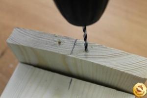
- a drill with large bits or a drilling machine;
- lathe, cutting machine(not necessary).
Puller manufacturing process:
Step one. Preparing the main part
The main part of the puller is a piece of thick-walled steel pipe; it acts as a frame. If the pipe is not strong enough and the loads are large. It can easily bend. The thickness of the pipe walls must be at least 3 mm.


We cut off the required piece from the pipe; the author uses a cutting machine for this, but everything can be done with a grinder. Now comes the hard part, you need to cut a window in the pipe. This can be done using a grinder; it takes a long time, but is quite doable.
Step two. We make the upper and lower supports
For the upper support, the author decided to use the thickest sheet steel possible. Cut out a circle of the required diameter. The author uses a grinder for work, first we cut out the “polygon”, and then using grinding wheel we bring it to perfection.
Cut out the other circle in the same way. Here the author used slightly thinner steel, but it’s better not to risk this, since the loads on both supports are approximately the same.


Finally, you need to finalize the supports. You need to drill a hole in the top support for the bolt. First we drill a small hole with a drill, and then drill it out to the desired diameter. The author used a lathe for these purposes.
As for the lower support, we also drill a hole in the center; its diameter should be slightly larger than the diameter of the axles from which you are thinking of removing the bearings. Then cut out a triangle shape for this hole. The supports are ready, let's move on!


Step three. Welding work
In this step we need to weld both supports to the body. The welding seam must be good and reliable; we set a higher current so that the metal melts well.


Having welded the supports, you now need to secure the nut. We wrap the bolt in it and insert it into the hole. We weld the nut well, but try not to overheat, as the metal may become soft. The author attaches the nut from above, but I would recommend fastening it from the inside, so it will rest on the support, and the tensile weld may not be very reliable.
Finally, all you have to do is secure the handle; for this, the author used a threaded rod. Using a handle will make it convenient to remove bearings that are not too rigid. Otherwise you can always use wrench.


Step four. Completion and testing
When you complete the welding work, you need to clean the welds, but this is more a matter of aesthetics; there is little practical benefit here. The author cleans off the slag using a wire brush, and cleans the seams with a grinding disc. The entire body can be polished. Now paint the homemade product so that the metal does not rust.


Finally, sharpen the end of the bolt so that it rests when screwed into the “hole” provided on any axis. Also, be sure to lubricate the threads well so that the puller will work easily and for a long time.
When carrying out repairs to the chassis and steering, there is almost always a need to remove ball joints or tie rod ends.
The special feature of these structural elements is that the support finger or tip has a conical shape, with which it fits into the seat.
During operation, the fit density increases so much that the surfaces of this joint practically stick to each other.
Additionally, moisture can get between the finger and the socket, causing pockets of corrosion that further seal the connection.
Therefore, to remove ball joints or tips, special pullers are used that allow you to press out the pin with minimal effort.
Types of pullers
The auto tools market offers wide choose such removable mechanisms, which can be divided into two types:
- Screw;
- Lever.
Screw pullers are considered universal and are suitable for working with almost any car.
The force in them is created by screwing the bolt into the puller body. The housing itself is put on the support eye, and when tightened, the bolt rests against the support pin and presses it out of the socket.
Lever removable mechanisms are no less effective, but they are larger in size, so they may not be suitable for every car.
For example, with such a puller on a VAZ-2107 you can still remove the upper ball joint, but you won’t be able to get to the lower one due to very limited space.
For these purposes, a special puller is used.

The essence of a lever puller comes down to the presence of two levers connected in the middle.
On the one hand, holes are made in them and a coupling bolt is installed.

To press out, one lever is installed between the eye and the support, while the second lever is placed under the finger.
When the bolt is unscrewed, due to the existing connecting axis, the ends of the levers begin to converge and the pin is pushed out.

But it is not necessary to purchase a removable mechanism; it can easily be made at home from improvised materials.
Puller type - WEDGE
The simplest puller is the so-called “wedge”. It does not belong to any type of removable mechanisms, but it is quite effective device for pressing out.
To make it, you only need an angle grinder (“grinder”), you can also use a machine with an abrasive wheel.
The blank will be a metal plate the size of a matchbox.
First, it is necessary to give the workpiece a wedge shape, for which we grind the metal with a grinder or machine so that the profile of the plate looks like a triangle. Then, using the same grinder, we make a cut in the middle 2/3 of the length of the workpiece from the side of the apex of the triangle, that is, from the thin side of the wedge. The width of the cut should be slightly larger than the thickness of the support pin, that is, you should get a kind of bracket.

If desired, you can weld a metal rod to the bracket, which will make it easier to work with the wedge in the future.
Pressing out a finger with a wedge is very simple. It is installed in the gap between the eye and the support body. And then the wedge is simply driven in with a hammer, which leads to the finger popping out of the socket.
The disadvantage of the wedge is that the boot will be damaged during the pressing process. Therefore, the wedge can only be used when replacing supports or tips.
If the suspension and steering mechanism are being repaired, which does not involve replacing the ball elements, it is better not to use a wedge.
Screw release mechanism
The second type of removable mechanism, which can be made from improvised means, is a screw release mechanism. It is perfect for replacing ball joints of classic VAZ models.
A special feature of the suspension design of these cars is that the upper and lower supports are located symmetrically to each other and the distance between them is not large.
It can be made at home only if you have drilling machine Or you will have to contact a turning workshop. This puller consists of only two parts.
To make it, you will need a square or hexagonal rod with 17 or 19 key edges, the length of which is 7 cm. Using a drilling machine, we make a hole in this rod and cut a thread for a bolt of 8. Screw in the bolt and that’s it – the puller is ready.

Let's look at how it works using the VAZ-2107 as an example. To press out the upper support, you need to unscrew the lock nut, but not completely, you do not need to remove it. Then we install the manufactured puller between the pins of the supports with the bolt screwed in until it stops.
To squeeze out the finger, we take two keys - with one we hold the manufactured body, and with the second we unscrew the bolt until the finger falls off the socket. After replacing the upper support, we do the same, but with the lower one.
Screw L-shaped
The third type of removable mechanism, which you can make yourself, is also a screw mechanism, but it has shown itself to be excellent and allows you to work on any car.
To make it you will need a round metal rod with a diameter of at least 10 mm and a length of 15-17 cm.
From it you need to make an L-shaped blank with a shoulder length of 5 cm. That is, we take a rod, measure 5 cm on it, clamp it in a vice and use a hammer to bend it 90 degrees.
We cut a thread on the long part of the workpiece and select a nut.
All that remains is to make the thrust bar. It can be made in the likeness of the wedge described above. That is, we take a plate, but 0.5 cm thick. On one side we make a cut for the support pin.
If necessary, you can reduce the thickness of the plate on the cut side by grinding off the metal layer. The main thing is that the plate fits into the gap between the support body and the eye, but it is not too thin, otherwise it will bend during the pressing process.
On the other hand, from the cut we make a hole for the L-shaped workpiece. All that remains is to put the plate on the long part of the rod. If the thread is not long enough to squeeze out the finger, you can place several washers under the nut.

This puller works like this: Unscrew the nut almost completely, install the plate in the gap between the support and the eye, and turn the rod so that the short arm rests against the finger.
Then we simply tighten the nut, while the plate will act as a stop, and the short arm of the rod will squeeze out the finger.


Screw made from angle
Another screw puller can be made from a metal corner and a welding machine.
To do this, take a corner with sides 7-8 cm and the same length, and a thickness of 0.3-0.5 cm.
We make a cut in one of the sides to secure the mechanism to the eye. From sheet metal 0.3 cm thick we cut out two triangles that will act as braces. They need to be welded on the sides to the corner. This will significantly increase the strength of the structure.
We take a 17 nut and a long bolt for it. We weld the nut itself perpendicular to the cut so that its hole faces the cut.
So that in the future the bolt can be easily positioned on the same axis with the pin, before securing the nut by welding, a spacer must first be welded onto the corner.
All that remains is to screw in the bolt and the puller can be used.


These are the simplest types of removable mechanisms that you can make yourself.
In general, there are a lot of options, and with a little imagination and basic knowledge of plumbing, you can easily come up with and make your own puller.
We offer some drawings for viewing.


Tool for unscrewing the support
We will consider another type, which is used not for pressing out the finger, but for removing the support itself.
The fact is that on a number of cars (Peugeot, Citroen) the ball joint is screwed into the lever. With time threaded connection turns sour, and it is quite difficult to unscrew this suspension element without a special tool.
But you can make the necessary puller yourself, rather than spending money on a factory one.
It is made from a thick-walled pipe 2\’\’ 8-9 cm long.

At the end of this pipe it is necessary to make 4 spikes with a width of 5 mm and a height of 7 mm, located at an angle of 90 degrees relative to each other.

That is, you should get 4 protrusions at the end of the pipe, evenly distributed around the circumference. This can be done using a hacksaw and a file, or with a grinder.
Very cool and useful thing. Bearing puller. A pipe, an iron plate, big washer, bolt nut.
First, mark on the pipe the size that needs to be cut. Weld a washer to the resulting segment. Place the nut evenly on the hole and weld it. Let's clean the uneven areas with a grinder.
Measure 1.5 centimeters and make a cut. On the other hand it's the same. Cut two small pieces from the plate. They will be inserted into two slots. The result is a puller.
How does this tool work? We put it on the bearing. We go behind him for two records. Rotate the bolt. It rests on the shaft and pulls the bearing off it. Using this device, you can easily remove it from the generator and electric motor. The outer diameter of the part should not exceed inner size pipes.
Video AVTO CLASS.
Second idea
Ayrat Valiakhmetov, the host of the youtube channel of the same name, has developed his own original idea. In the store, such tools are not cheap. So I decided to do it myself. I took a metal strip 30 mm wide and 4 mm thick. I cut it into strips. Cooked. Plates. Hooks to grip the bearing. Two cuts are made with a grinder. Two nuts are inserted and welded. I took the worm from an old Soviet clamp. Hardened steel. To make the tool universal, I made 4 holes on each side. Can be installed at any width. If necessary, the paws are pulled out and turned over to the other side. You can pull out the bearing.
When repairing electric motors, in addition to open-end wrenches and a set of heads, you must also have in your arsenal several pullers for tightening bearings.
One universal one simply won’t do. If you have electric motors from 1 kW to 100 kW on your site, then you need to have 2-3.
I have two bearing pullers in my arsenal. Now there is a large selection of pullers on the markets, and you can purchase them. But if you have the material, a lathe, gas and electric welding, and the desire, then you can make a puller yourself. And I assure you, it will serve you for decades.
You should definitely use three-jaw pullers: they are the most convenient. I will also indicate the dimensions of my pullers, which have long been tested during repairs. Let's start with a small one, with which you can remove bearings from sizes 202 to 308, large - 317 and more. We will need sheet metal 10 mm thick and

metal round timber with a diameter of 30 mm (for a large one - metal 15 mm and round timber with a diameter of 50 mm).
First of all, we make a drawing (pattern) of the puller legs. We make the length of the legs 200 mm (at the end of the article in PDF format I will post patterns of the legs of the small and large pullers). Next on sheet metal We draw a drawing according to the pattern. You need to cut the legs with a gas cutter (propane and oxygen). After cutting, we process the blanks using coarse sandpaper.
Gradually we bring the sizes of the three legs to the same size. There is no need to achieve too ideal dimensions; a difference of 1 mm will not play a negative role in the design. When the legs are made and adjusted, in the upper part we drill two holes (for a small expansion of possibilities) with a diameter of 8 or 10 mm bolts (for a large 12 or 14 mm there are 3 holes) for attaching the presser foot to the core of the puller. We do the same with the two remaining legs. We drill holes in them along the first leg, using it as a template. Here we must try to prevent the discrepancy in size from allowing the capture of the bearing to be removed to occur simultaneously. Here's a short description of how to make puller legs.
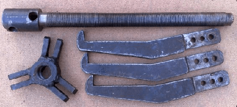
The next detail is the core. For the core for a small puller, we will need round metal with a diameter of 30 mm and a length of 35 mm (for a large one, 50x45 mm, respectively). In the workpiece, we drill a hole for a 16 mm thread (for a large puller, there is a hole in its workpiece with a diameter of 30 mm) and cut the thread, preferably with a fine pitch. In the prepared part for the core we apply markings, three marks at 120 degrees. And to these places we electric weld two to the marks of the paw holder (the distance between the holders should be as thick as the paw). I think there is no need to describe in detail how to prepare them, since there is no need to adhere to any strict rules and sizes. After welding work We process this part using coarse sandpaper. Now, having tried on the paw, we drill holes in the holders. The holes must be drilled at a distance from the center, so that the installed foot has good movement to the side to capture larger bearings.
And the third part of our puller is the screw. For the first puller we make it 350 mm long, the thread length is 280 mm, for the second - 500 mm long, for the thread 420 mm. Next on lathe we process the workpieces and cut the threads. In the upper part of the screw, where there is no thread, we drill through holes with a slight offset in height and perpendicular to each other. These are holes for mounting or a knob. Diameter is at your discretion. The beginning of the screw can be narrowed in diameter by a small distance. I don't describe the details. Everything can be seen in the photographs.
We made these pullers with a mechanic over 12 years ago. All these years I have had no problems with removing bearings and coupling halves. And most importantly, the quality turned out to be from Soviet times. Like this necessary tool you can easily do it yourself.