In today's article, I will tell you how to make a robot that bypasses obstacles based on the Arduino microcontroller with your own hands.


To make a robot at home, you will need the microcontroller board itself and an ultrasonic sensor. If the sensor detects an obstacle, the servo will allow it to go around the obstacle. By scanning the space on the right and left, the robot will choose the most preferred path to bypass the obstacle.
Codebender is a browser-based IDE, it's the easiest way to program your robot from a browser. You need to click on the "Run on Arduino" button and that's it, nowhere is easier.
Insert the battery into the compartment and press the function button once, and the robot will move forward. To stop movement, press the button again.
/* Arduino Obstacle Avoiding Robot with a servo motor and an ultrasonic sensor HC-SR04 LED and buzzer */ //Libraries #include #include "Ultrasonic.h" //Constants const int button = 2; // Button pin to pin 2 const int led = 3; // LED pin (via resistor) to pin 3 const int buzzer = 4; //Buzzer pin to pin 4 const int motorA1= 6; //positive (+) motor A pin to pin 6 (PWM) (from L298 module!) const int motorA2= 9; //negative pin (-) of motor A to pin 9 (PWM) const int motorB1=10; // positive (+) motor B pin to pin 10 (PWM) const int motorB2=11; // negative pin (-) of motor B to pin 11 (PWM) Ultrasonic ultrasonic(A4 ,A5); //Create an object ultrasonic(trig pin,echo pin) Servo myservo; //Create a Servo object to control the servos //Variables int distance; //Variable for storing the distance to the object int checkRight; int checkLeft; int function=0; //Variable for storing the robot function: "1" - movement or "0" - stopped. Stopped by default int buttonState=0; //Variable to store the state of the button. By default "0" int pos=90; //variable to store the position of the servo. By default 90 degrees - the sensor will look forward int flag=0; //useful flag for storing the state of the button when the button is released void setup() ( myservo.attach(5); //Servo pin connected to pin 5 myservo.write(pos); // tells the servo to go to position in variable " pos" pinMode(button, INPUT_PULLUP); pinMode(led, OUTPUT); pinMode(buzzer, OUTPUT); pinMode(motorA1,OUTPUT); pinMode(motorA2,OUTPUT); pinMode(motorB1,OUTPUT); pinMode(motorB2,OUTPUT) ; ) void loop() ( //Checking the state of the button buttonState = digitalRead(button); unsigned long currentMillis = millis(); //calculating... //Changes the main function (stopped/moving) when the button is pressed if (buttonState = = LOW) (//If the button is pressed once... delay(500); if (flag == 0)( function = 1; flag=1; //change the flag variable ) else if (flag == 1)( / /If the button is pressed twice function = 0; flag=0; //change the flag variable again ) ) if (function == 0)( //If the button is released or pressed twice, then: myservo.write(90); //set for servo 90 degrees - the sensor will look forward stop(); //robot stays still noTone(buzzer); //buzzer is off digitalWrite(led, HIGH);// and the diode is on ) else if (function == 1)(//If the button is pressed, then: //Read the distance... distance = ultrasonic.Ranging(CM); //Tip: Use "CM" for centimeters and "INC" for inches //Check for objects. .. if (distance > 10)( forward(); //Everything is clear, moving forward! noTone(buzzer); digitalWrite(led,LOW); ) else if (distance<=10){ stop(); //Обнаружен объект! Останавливаемся и проверяем слева и справа лучший способ обхода! tone(buzzer,500); // издаём звук digitalWrite(led,HIGH); // включаем светодиод //Начинаем сканировать... for(pos = 0; pos =0; pos-=1){ //идём от 180 градусов к 0 myservo.write(pos); // говорим серво пройти на позицию в переменной "pos" delay(10); // ждём 10 мс, пока сервопривод достигнет нужной позиции } checkRight= ultrasonic.Ranging(CM); myservo.write(90); // Датчик снова смотрит вперёд //Принимаем решение – двигаться влево или вправо? if (checkLeft checkRight){ right(); delay(400); // задержка, меняем значение при необходимости, чтобы заставить робота повернуться. } else if (checkLeft <=10 && checkRight <=10){ backward(); //Дорога перекрыта... возвращаемся и идём налево;) left(); } } } } void forward(){ digitalWrite(motorA1, HIGH); digitalWrite(motorA2, LOW); digitalWrite(motorB1, HIGH); digitalWrite(motorB2, LOW); } void backward(){ digitalWrite(motorA1, LOW); digitalWrite(motorA2, HIGH); digitalWrite(motorB1, LOW); digitalWrite(motorB2, HIGH); } void left(){ digitalWrite(motorA1, HIGH); digitalWrite(motorA2, LOW); digitalWrite(motorB1, LOW); digitalWrite(motorB2, HIGH); } void right(){ digitalWrite(motorA1, LOW); digitalWrite(motorA2, HIGH); digitalWrite(motorB1, HIGH); digitalWrite(motorB2, LOW); } void stop(){ digitalWrite(motorA1, LOW); digitalWrite(motorA2, LOW); digitalWrite(motorB1, LOW); digitalWrite(motorB2, LOW); }
By clicking the "Edit" button, you can edit the sketch for your needs.
For example, by changing the value "10" of the measured distance to an obstacle in cm, you will decrease or increase the distance that the Arduino robot will scan in search of an obstacle.
If the robot is not moving, it can change the contacts of the electric motors (motorA1 and motorA2 or motorB1 and motorB2).
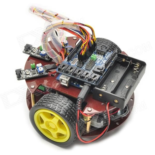
Step 7: Completed Robot

Your homemade robot that avoids obstacles based on the Arduino microcontroller is ready.
Hi all. This article is a short story about how do robot their hands. Why a story, you ask? All due to the fact that for the manufacture of such crafts it is necessary to use a significant amount of knowledge, which is very difficult to present in one article. We'll walk through the build process, take a peek at the code, and ultimately bring the creation of Silicon Valley to life. I advise you to watch the video in order to have an idea of \u200b\u200bwhat should happen in the end.
Before moving on, please note the following, that in the manufacture crafts used a laser cutter. You can refuse a laser cutter if you have sufficient experience in working with your hands. Accuracy is the key to completing a project successfully!

Step 1: How does it work?

The robot has 4 legs, with 3 servos on each of them, which allow it to move its limbs in 3 degrees of freedom. He moves with a "creeping gait". Let it be slow, but one of the smoothest.
First you need to teach the robot to move forward, backward, left and right, then add an ultrasonic sensor, which will help detect obstacles / obstacles, and after that a Bluetooth module, thanks to which the robot control will reach a new level.
Step 2: Required Parts

Skeleton made of plexiglass 2 mm thick.
The electronic part of the homemade product will consist of:

- 12 servos;
- arduino nano (can be replaced with any other arduino board);

- Shield for servo control;
- power supply (in the project, a 5V 4A power supply unit was used);

- ultrasonic sensor;
- hc 05 bluetooth module;
In order to make a shield you will need:

- circuit board (preferably with common lines (buses) of power and ground);
- inter-board pin connectors - 30 pcs;
- sockets per board - 36 pcs;

- wires.
Tools:
- Laser cutter (or skillful hands);
- Super glue;
- Hot glue.
Step 3: Skeleton

Let's use a graphics program to draw the component parts of the skeleton.
After that, in any available way, we cut out 30 parts of the future robot.
Step 4: Assembly

After cutting, remove the protective paper coating from the plexiglass.

Next, proceed to the assembly of the legs. Fasteners built into parts of the skeleton. All that remains to be done is to put the pieces together. The connection is quite tight, but for greater reliability, you can apply a drop of superglue to the fasteners.

Then you need to modify the servos (glue a screw opposite the servo shafts).

With this refinement, we will make the robot more stable. The refinement needs to be done only for 8 servos, the remaining 4 will be attached directly to the body.

We attach the legs to the connecting element (curved part), and it, in turn, to the servo on the body.
Step 5: Making the Shield

Making the board is quite simple if you follow the photos presented in the step.


Step 6: Electronics

Fix the servo pins on the arduino board. The pins must be connected in the correct sequence, otherwise nothing will work!


Step 7: Programming

It's time to bring Frankenstein to life. First, load the legs_init program and make sure that the robot is in the position shown in the picture. Next, load quattro_test to see if the robot responds to basic movements such as forward, backward, left, and right.

IMPORTANT: You need to add an additional library to the arduino IDE. The link to the library is given below:
The robot must take 5 steps forward, 5 steps back, turn left 90 degrees, turn right 90 degrees. If Frankenstein is doing everything right, we are moving in the right direction.

P. S: install the robot on the cup as a stand, so that each time it does not set it to the original point. Once the tests have shown the normal operation of the robot, we can continue testing by placing it on the ground / floor.
Step 8: Inverse Kinematics

Inverse kinematics is what actually controls the robot (if you are not interested in the mathematical side of this project and you are in a hurry to finish the project, you can skip this step, but knowing what drives the robot will always be useful).

In simple terms, inverse kinematics or IK for short is the "part" of the trigonometric equations that determine the position of the sharp end of the leg, the angle of each servo, etc., which ultimately determines a couple of preliminary settings. For example, the length of each step of the robot or the height at which the body will be located during movement / rest. Using these predefined parameters, the system will extract the amount by which each servo must be moved in order to control the robot with given commands.
A little about the robot. First of all, the project had to be as inexpensive as possible. The hull was created without any calculations and balancing, the main requirement for the hull is the minimum dimensions. So let's start collecting this robot.
Parts list:
1. A set of body parts and paws made of 1.5 mm plexiglass.
2. Arduino Mega or Uno (Mega is used) - 1 pc.
3. Micro servo (using TowerPro SG90) - 8 pcs.
4. Ultrasonic rangefinder HC-SR04 - 1 pc.
5. Battery size 18560, 3.7V (TrustFire 2400 mAh is used) - 2 pcs.
6. Battery holder size 18560 (using a converted container - packaging) - 1 pc.
7. PCB stand 25mm. (such racks are used) - 4 pcs.
8. Part of the breadboard.
9. Jumper wires.
10. Screw DIN 7985 M2, 8 mm. - 18 pcs.
11. Nut DIN 934 M2 - 18 pcs
Assembling the Z-RoboDog robot:
1. The body of the robot is made of 1.5mm transparent plexiglass. All parts are laser cut according to the drawing made in the CorelDraw program:
2. Glue the body with second glue. The strength of the glued body will be enough. When assembling, consider the position of the holes on the bottom cover (look at the photo), but rather attach the board and make sure everything matches. Fasten the side walls so that the holes for the wires are closer to the rear wall. The wider hole on the back wall is for the USB cable, please keep this in mind when assembling.


3. Mark and drill holes (drill 2 mm.). Fasten the servos to the housing using bolts and nuts (items 10, 11 from the list). The front servo shafts should be closer to the front wall. The rear servo shafts are closer to the rear wall.


4.1. Gather the paws. Take the upper parts of the paws (with two holes). Mark the middle of the part. Substituting the servo rocker, mark the attachment points with screws and drill holes (drill 1.5 mm). Fasten the rocking chairs so that the screw heads are on the side of the seats. Rocking chairs fasten from different sides and the seats for the shafts before were in the opposite direction.


4.2. Mark and drill the holes for mounting the servos (drill bit 2 mm). The shafts of the fixed servos should be closer to the narrow edge of the foot.


4.3. To prevent the paws from slipping, stick rubber on them, for example. But the front part of the paw should not be glued; when walking, the dog can catch and get stuck. I stuck strips of sticky mat from the car.

5. Mark and drill the holes for mounting the ultrasonic range finder (drill bit 2 mm). Mount the rangefinder with the contact legs pointing up.

6. Install the battery holder so that it is located in the middle of the case. Fix the Arduino board and connect all the components. Part of the breadboard was used to branch out the power supply.

Setting up and launching the Z-RoboDog robot:
At this point, you will have to install the legs yourself so that you can calibrate the steps. The main problem is rocking chairs, which are mounted on shafts only in certain positions. And also the servos themselves may differ in operating degrees.
This is how my dog's paws look like at the extreme points of the servo angles (variables zs1, zs2, zs3, etc.). Try to put the paws as in the photo. Visually, the paws should be in the same positions.

In the main stance, you can also expose the paws. After that, do not forget to screw the rocking chairs to the servo shafts.


Software part of Z-RoboDog:
The code is very simple, comments are added everywhere. All movements are in an array, so as not to get confused in the numbers, I used variables for each servo. For example, s1 is servo 1, s2 is servo 2, and so on. To make it easier to understand, I offer you the following scheme.

The paws are numbered on the diagram, each part of the paw is associated with a servo that moves it. Also, for each paw, the directions of movement are indicated, the plus and minus signs indicate where the paw will move when the angle increases or decreases. The initial angles are the corners of the main rack (s1, s2, s3, etc.). For example, if you need to extend the 2nd leg, you must increase the angle of s3 and s4, in the array it will look like this (s1,s2, s3+100,s4+50, s5,s6, s7,s8). Here is the complete sketch. The code was written by virtue of my knowledge, please let me know if I chose the wrong implementation path.
Video:
Sketch in archive: You do not have access to download files from our server
Our dear readers, we are opening a series of articles on creating a robot based on Arduino. It is assumed that the reader is a beginner and has only a basic knowledge of the subject. We will try to state everything as detailed and understandable as possible.
So, an introduction to the problem:
Let's start with a concept: we want a robot that can move around the room on its own, while avoiding all obstacles in its path. The task was set.
Now let's figure out what we need:
- Platform (case). There are options here: do everything yourself, buy parts and assemble them, or buy ready-made. Choose what you like


The kit usually comes with a platform and one motor for two driving wheels (caterpillar) and a battery compartment. There are options for all-wheel drive - on a 4-wheel motor. For beginners, we recommend taking tank-type platforms

Two driving wheels and a third support.
- Next, we need a rangefinder. Sonar (aka rangefinder, aka Ultrasonic module) As a rangefinder, initially the choice was between ultrasonic and infrared. Since the characteristics of ultrasonic are much better (the maximum range is about 4-5 meters, versus 30-60 cm), and the price is about the same, the choice fell on Ultrasonic. The most common model is HC-SR04.

- Engine driver.
How to be? The first thing that comes to mind is to put a transistor on the output of the microcontroller and feed the motors from it. This is certainly good, but it won’t work if we want to start the motor in the other direction ... But H will do this job well - a bridge, which is a slightly more complex circuit than a pair of transistors. But in this case, there are plenty of them in the form of ready-made integrated circuits, so I think there is no need to reinvent the wheel - we will buy a ready-made one. In addition, the price is favorable - 2-3 dollars ... Let's move on. For these purposes, we will buy an L293D chip, or even better, a Motor Shield based on it.


Motor shield on the L298N chip
- Sound Generation - Piezo Buzzer
The simplest option for generating sound is to use a piezo emitter.

Piezoceramic emitters (piezoelectric emitters) are electroacoustic sound reproduction devices that use the piezoelectric effect. (the effect of the occurrence of dielectric polarization under the action of mechanical stresses (direct piezoelectric effect). There is also an inverse piezoelectric effect - the occurrence of mechanical deformations under the influence of an electric field.
Direct piezo effect: in piezo lighters, to obtain a high voltage on the spark gap;
Inverse piezoelectric effect: in piezoelectric emitters (effective at high frequencies and have small dimensions);)
Piezo emitters are widely used in various electronic devices - alarm clocks, telephones, electronic toys, household appliances. The piezoceramic emitter consists of a metal plate, on which a layer of piezoelectric ceramics is deposited, having a conductive coating on the outer side. The plate and the coating are two contacts. The piezo buzzer can also be used as a piezoelectric microphone or sensor.
That's all we need for the first time. To begin with, we will consider, in the form of separate lessons, how to assemble and make these parts work separately.
Lesson 2
Lesson 3. Arduino and Motor Shield based on L298N
Lesson 4
Lesson 5
But also with the purchase of a ready-made full-fledged robot based on this board. For elementary school or preschool children, such ready-made Arduino projects are even preferable, because. The “non-living” board looks boring. This way suitable for those who are not particularly attracted to electrical circuits.
By purchasing a working robot model, i.e. actually finished high-tech toy, you can awaken interest in the independent design and creation of robots. Having played enough of such a toy and figured out how it works, you can start improving the model, take everything apart and start assembling new projects on Arduino using the freed board, drives and sensors. The openness of the Arduino platform allows you to make new toys from the same components.
We offer a small overview of ready-made robots on the Arduino board.
Arduino controlled car via Bluetooth
Bluetooth controlled car, costing just under $100. Supplied disassembled. In addition to the case, motor, wheels, lithium battery and charger, we get an Arduino UNO328 board, a motor controller, a Bluetooth adapter, a remote control, and more.
Video featuring this and another robot:
A more detailed description of the toy and the opportunity to buy on the website of the DealExtreme online store.
Arduino Turtle Robot
Robot Turtle Kit worth about $90. Only the shell is missing, everything else necessary for the life of this hero is included: Arduino Uno board, servos, sensors, tracking modules, IR receiver and remote control, battery.

Turtle can be bought from DealExtreme, a similar cheaper robot on Aliexpress.
Tracked car on Arduino, controlled from a cell phone
Tracked vehicle controlled via Bluetooth from a cell phone, costing $94. In addition to the caterpillar base, we get an Arduino Uno board and an expansion board, a Bluetooth board, a battery and a charger.

The tracked vehicle can also be bought on the DealExtreme website, there is also a detailed description. Maybe more interesting iron arduino tank on Aliexpress.
Arduino car driving through mazes
Car driving through labyrinths, costing $83. In addition to motors, the Arduino Uno board and other necessary things, it contains tracking modules and obstacle avoidance modules.
Finished robot or robot frame
In addition to the option of using ready-made kits for creating Arduino robots, discussed in the review, you can buy a separate frame (body) of the robot - it can be a platform on wheels or a caterpillar, a humanoid, a spider, and other models. In this case, the filling of the robot will have to be done independently. An overview of such cases is given in ours.
Where else to buy ready-made robots
In the review, we chose the cheapest and most interesting, in our opinion, ready-made Arduino robots from Chinese online stores. If there is no time to wait for a package from China, there is a large selection of ready-made robots in Amperka and DESSY online stores. ROBstore online store offers low prices and fast delivery. List of recommended stores.
You might also be interested in our overviews of Arduino projects:

Arduino training
Not sure where to start learning Arduino? Think about what is closer to you - assembling your own simple models and gradually increasing their complexity, or getting to know more complex, but ready-made solutions?


