Almost all pump owners have come across the concepts of cavitation and pump NPSH. It should be noted that having the right information on these issues will help prevent many unpleasant breakdowns, save money and extend the life of the device.
In order to understand what is the NPSH of a pump, it is necessary to know exactly the definition of cavitation.
Definition of cavitation
Cavitation also causes strong vibration and noise during the operation of the device, from which the service life of many components is sharply reduced. That is why cavitation of pumps and their elimination is an important task, which should be approached with special attention. Having dealt with the definition, we proceed to clarify the next question.
Pump NPSH
Strictly speaking, this is the amount necessary in order to maintain desired level pressure in the liquid to avoid cavitation. The data can be obtained from the company that produced the device, which are designated NPSHR. The installation and piping of the pump should be carried out based on the indicators of the stock and accurate calculations, made taking into account: terrain, water level, pressure, head, suction losses, etc.
Pump cavitation and their elimination- the main problem of many owners of pumps. There is a main rule, following which you can avoid it. It says: there must be more liquid at the inlet than at the outlet. To achieve this, you can use the following options:
- install suction pipe larger diameter;
- install the device near a water source;
- place the suction pipe in one plane, preferably without a large number of bends or with smooth turns, it is also worth purchasing a pipe from a material that does not cause strong resistance;
- you can try to increase the pressure on the suction side by raising the water level in the intake tank or by lowering the level of the pump itself.
It is also necessary to regularly check the operation of the device and, at the slightest suspicion of cavitation, take urgent measures. So the pump will last a long time without serious damage.
The cavitation energy reserve is the excess of the total specific energy of the liquid over specific energy its saturated vapors at the inlet to the pump. This specific indicator can be:
volumetric (per 1 cubic meter)
Mass (per 1 kg of mass)
![]() ;
;
weight (per 1 newton of weight)
![]() ,
,
With large cavitation reserves, cavitation phenomena are absent and the pressure and power values do not change at different cavitation reserves. The occurrence of cavitation leads to a decrease in pump head, power and efficiency. The mode in which the drop in pressure and power begins is called first critical. It corresponds to the first critical cavitation reserve Δh cr. With a further decrease in the cavitation reserve (i.e., an increase in suction vacuum), a sharp decrease in pressure and power occurs. The cavitation reserve in this mode is called second critical or stall Δh cf. For low-speed pumps, the first critical mode may not be detected. In this case, we have to limit ourselves to only the second critical mode.
The operation of the pump between the first and second critical mode can be allowed if there is no requirement for reliability or if the operation is short-term. To do this, so that it does not happen that the pump, due to insufficient consideration of all factors, operates in the cavitation mode, a slight excess of the permissible cavitation reserve over the critical one is prescribed (Δh add = φ h cr, φ = 1.1 ÷ 1.3). A large value of φ is assigned if the calculation of the allowable cavitation reserve is carried out according to the second critical reserve.
Knowing the permissible cavitation reserve for a given pump, it is possible to calculate the permissible vacuum and geometric suction height for certain modes of its operation according to the formulas:
P in x is the allowable absolute pressure at the pump inlet, referred to the pump axis, Pa;
R b - barometric pressure, Pa;
R o - overpressure on the suction surface, Pa;
P n is the vaporization pressure of the liquid, Pa;
Δh add - admissible cavitation energy reserve, m;
V in x is the speed at the pump inlet, m/s;
- total hydraulic losses in the suction pipeline, m.
In contrast to the permissible NPSH, the vacuum suction head depends not only on the design of the pump and its mode of operation, but also on the type and temperature of the liquid and barometric pressure.
Russian scientist Professor S.S. Rudnev established the dependence of the cavitation reserve Δh on the parameters of the pump. He proposed a formula for calculating the cavitation reserve, depending on the value of the parameters of the pump in the nominal mode.
 ,
,
here: n is the frequency of rotation of the pump rotor, rpm;
Q - pump flow, m 3 / s;
C is the cavitation coefficient of pump speed.
Using the Rudnev formula, we get:
 ,
,
where: n’ rpm, Δh kr m.st. liquids.
In contrast to H svak and Δh, the coefficient C for all geometric similar pumps during their operation in similar modes is constant.
Coefficient C is used as the main characteristic of the cavitation qualities of pumps and is called the cavitation coefficient of speed.
Having chosen its value depending on the purpose of the pump, the permissible critical suction height is calculated or, with a known value of Δh cr, the maximum speed of the pump rotor n' is determined.
For vane pumps with average cavitation qualities С=800-1000; pumps with increased cavitation qualities have C=1300 and more.
Vortex pumps have low cavitation qualities (C<600). Их кавитационные качества повышают путем применения предвключенных центробежных ступеней или осевых колес.
To identify the cavitation qualities of pumps, their cavitation tests are carried out, as a result of which experimental partial cavitation characteristics are obtained for a number of pump operation modes in terms of supply.
The partial cavitation characteristic (Fig. 4.1) is the dependence of the head H and power N of the pump on the cavitation energy reserve Δh at a constant supply Q and cleanliness of rotation n. According to private graphs of cavitation characteristics, the numerical value of the critical energy reserve Δh cr is determined (at the point at which the head according to the graph H = f (Δh) decreases by 2÷3% or the pump fails), the allowable vacuum suction height is calculated and graphs of generalized cavitation characteristics ![]() .
.
4.3 Description of the laboratory bench
Cavitation tests of the vortex pump are carried out on the same stand as the energy ones (laboratory work No. 3, Fig. 3.1). The installation consists of a vortex pump 3 driven by an asynchronous electric motor operating at a constant rotor speed. Water is sucked in from the tank 12 through the intake pipeline 1, which includes a complex
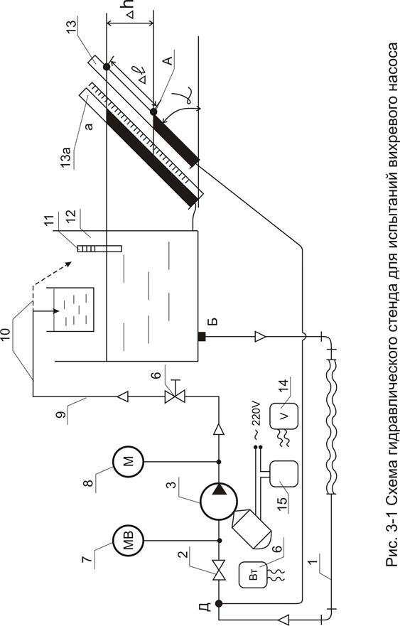
resistance between points B-D, used as a throttle flow meter, and a valve (variable resistance 2) with the help of which, during the experiments, the pressure at the pump inlet is changed, i.e. cavitation energy reserve of the liquid at the pump inlet. Through the pressure pipeline 9 and 10 (flexible hose), on which the control valve 6 is installed, the water returns to the tank.
When testing, the following instruments are used, installed on the stand: vacuum gauge 7, pressure gauge 8, micropiezometer with an inclined tube 13, which measures the pressure drop across the throttle flow meter - complex resistance (D-A); wattmeter 6 (or ammeter 15 and voltmeter), which measure the power consumption; thermometer 11 for measuring the temperature of the liquid.
The flow (pump operation mode) is set according to the readings of the micropiezometer 13, previously calibrated for flow.
4.4 Procedure for carrying out cavitation tests of the pump.
1. The most important private cavitation characteristic, the results of which determine the cavitation qualities of the pump, is the characteristic taken at the nominal (specification) operating mode. Based on the results of these experiments, the value of the cavitation coefficient of speed C of the tested pump is calculated. The pump flow in this mode is determined by the energy characteristics obtained when testing the vortex pump (see the graph η=f(Q) in the report on laboratory work No. 3). As a variant of the task, the teacher may offer to conduct tests with other parameters close to the nominal.
Cavitation reserve, specific suction rate and suction energyWhen designing pumping systems, it is important to provide adequate NPSH for proper pump operation. Insufficient NPSH can severely limit pump selection or even require costly redesign of the system. On the other hand, providing an overestimated NPSH may unnecessarily increase the cost of the system. Specific absorption rate can be of help in this situation.
Its value is defined as:
Where N- pump speed (rpm)
m3/h- Pump flow at the point of highest efficiency at the impeller inlet (For pumps with double suction impeller, the flow is halved)
NPSH- cavitation reserve of the pump at the point of highest efficiency.
For this pump, specific suction rate, in general case, constant - it does not change when the pump speed changes. Experience shows that 9000 is a sufficient value for the specific absorption rate. A pump with a minimum specific suction rate of 9000 is fully operational and has no reason for severe operating limitations.
Example:
Consumption 454 m3/h; head 183 meters. What value of NPSH is required?
Suppose: for a head of 180 meters, work is required at 3550 rpm 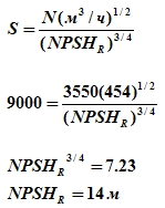
A related problem exists when selecting a new pump in existing systems, especially at high flow rates. Specific Suction Velocity will highlight applications where NPSH may limit pump selection.
Example:
Existing system: Flow 454 m3/h; head 183 meters: NPSHa 9 meters. What is the maximum speed at which the pump can operate without exceeding the NPSH? 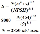
To operate the pump at this speed, a gearbox is required, and at this speed the pump may not develop the required head. At a minimum, NPSH limits pump selection.
The system is the same. Is it advisable to choose a double suction pump? For a double suction pump, the flow rate is halved. 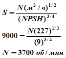
The use of a double suction pump is one way to ensure the NPSH of the system.
The amount of energy in the pumped liquid that instantly vaporizes and then collapses back into the liquid in the high pressure area as it enters the impeller determines the degree of noise and/or cavitation damage. Suction energy is defined as:
Where De= impeller inlet diameter (in inches)
Sg= Liquid density (1.0 for cold water)
High suction energy starts from 160x10 6 for single suction pumps and 120x10 6 for double suction horizontal pumps. Extremely high suction energy starts from 1.5 times the high suction energy. For calculation, the impeller inlet diameter is usually taken as 90% of the suction port size for single suction pumps and 75% of the suction port size for double suction pumps.
Example:
Specific suction rate 9000, pump speed 3550 rpm, suction port size 6", density 1.0, single suction pump. 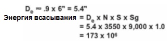
Since 173x10 6 >160x10 6 , this is a high suction energy pump.
CENTRIFUGAL PUMP OPERATION WITHOUT CAVITATION PROBLEMS
General
Exists a large number detailed publications on the importance of the value of the cavitation reserve. In practice, however, mistakes are made all the time, with damage to the pump and even failure of the entire system as a result. Therefore, these recommendations are intended to show how the NPSH of a system can be made more suitable using different parameters and what criteria are important when choosing a pump.
NPSH means admissible NPSH. A system that, for example, cold water flows into the pump from a height of 1m without pressure drop has an NPSH value of approximately 11m (not 1m).
NPSH=11m
A = available
In this case, only a pump with an NPSHr value of 10.5m or less can be used, for safety reasons there is a difference of 0.5m
NPSH=10.5m
R = required
Cavitation reserve of the system
Here is a standard formula that is fully consistent with practice. The latest designations are used in accordance with DIN 24 260 Part 1, edition September 1986. 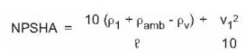
NPSHA (previously NPSHavail) in meters, NPSH
ρ1 (previously ρs) in bars
Excessive pressure in the suction pipe directly in front of the pump (if the pressure is below atmospheric, the value is taken with a minus sign)
ρ amb (previously ρ B) in bar abs.
Atmospheric pressure (typically 1.013 bar abs.)
ρv (previously ρD) in bar abs.
Saturated vapor pressure of a liquid at operating temperature.
ς in kg/dm3
Density of a liquid at operating temperature.
V1 (previously VS) in m/s
Velocity of the pumped liquid in the suction pipe.
This data refers directly to the center of the suction port. For simplicity, the free fall acceleration is assumed not to be 9.81 m/s2, but 10.0 m/s2.
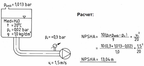 |
| Example 1 |
Tips for solving problems with NPSH.
NPSH r - cavitation wear reserve
This value can be roughly calculated, but is usually determined on a test rig, at a specific pump speed, at a specific impeller diameter, and at a specific feed rate. The NPSHR value of the pump is determined by refining the total pump head at various suction heads. In order to obtain various suction pressures, the pressure in the supply tank is reduced by means of a throttle device. A combination of these methods is often used to achieve reduced pressure.
The greater the vacuum at the impeller inlet, the greater the cavitation occurs. This weakens the overall head of the pump. The value at which the total head of the pump drops by 3% as a result of this cavitation is commonly referred to as the NPSHR value of the pump.
Several tests are needed at the same delivery and at different suction pressures before a 3% head drop is determined through repeated measurements, calculations, etc.
To determine the NPSHR pump NPSH curve, these measurements are made at various flows and at different meanings impeller diameter. Compiling a series of such curves is expensive.
Cavitation reserve of the NPSHa system< Кавитационный запас насоса NPSHr, что можно сделать?
Individual quantities in the formula related to the system:
ρ1 - increase the pressure in the suction pipe, i.e. more liquid supply, increase the liquid level in the supply tank, or raise the suction tank more high level or lower the pump, for example, one floor lower.
On the other hand, the nominal diameter of the suction pipe must be of the appropriate size, and it must also be ensured that valves and other pipeline accessories in the suction line has the lowest possible friction loss coefficient so that ρ1 in front of the pump is as high as possible. For example, the most suitable are ball valves that are completely open in cross section.
ρamb - no way to change.
ρv - in some cases, the liquid may be cooled before entering the pump in order to reduce the pressure of saturated vapors.
ς - there is no possibility to change.
V1 - if the value corresponds to the dimensions of the suction port of the pump, further consideration is not important. Of course, the value of V1 should be as small as possible, as already mentioned for ρv.
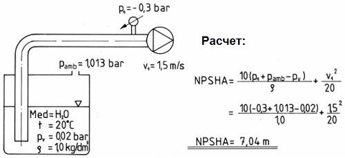 |
| Example 2 |
The following troubleshooting steps can be applied to the pump:
Feed rate reduction- The NPSH of the pump usually becomes smaller and the NPSH of the system increases. If necessary, distribute the flow to several pumps, for example, use a standby pump.
Installing a larger impeller- In many cases, the NPSH of the pump gets better, but the energy consumption, of course, also increases.
Decreasing Speed - Pumps running at lower speeds have better NPSH. In many cases, however, a larger pump becomes necessary.
Installing a larger impeller and reducing the speed- If the pump has a relatively small impeller, this solution is ideal in terms of hydraulics. (smoother operation, less wear).
Pump operation with cavitation- IN special occasions, the pump supplier and the system operator can agree that there may be a head drop of more than 3%. However, this must be carefully set so that a complete head drop does not occur.
Choose a pump with the best NPSH - Large pumps in many cases have the best value of the NPSH at the same supply. If necessary, it is possible to install special impellers specially designed for good suction.
Other
Plastic pumps are usually relatively insensitive to cavitation. It is also difficult to hear the phenomenon itself, because plastic is a good sound insulator.
Magnetic drive pumps can be considered single mechanical seal pumps. The temperature of the liquid must be at least 20°C below the boiling point.
Influence of saturated vapor pressure
In this context, the importance of saturation vapor pressure must again be emphasized:
Saturated vapor pressure is a function of temperature. Liquids that are pumped close to saturated vapor pressure are especially dangerous because even a slight increase in temperature can cause evaporation. Not only a general fluctuation in temperature, but also difficult cooling or uncontrolled heat input can cause an emergency shutdown. Insufficient heat dissipation can be, for example, due to too low a feed rate. Heat input can occur due to increased friction in the mechanical seal, increased friction in the bearings in hermetically sealed pumps with a magnetic drive, and also, especially, due to heat losses (eddy currents) in the metal bowl in pumps without a seal.
Pumps with double mechanical seals are the least sensitive, because contact surfaces are lubricated in a separate circuit.
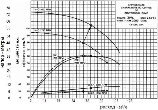
PUMP CURVES
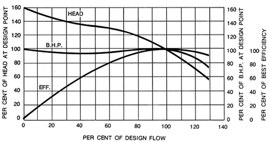
The characteristics of a centrifugal pump can be graphically shown on the characteristic curve. A typical characteristic curve shows total head, effective power, efficiency, and NPSH plotted as a function of pump flow.
Figures 1,2 and 3 show dimensionless curves that show general form curves for various types pumps. They show the head, power and efficiency shown as a percentage of their value depending on the type of pump or the point of maximum efficiency of the pump.
Rice. 1 shows that the head curve of a centrifugal pump is relatively flat and the head gradually decreases with increasing flow. Note that the power gradually increases over the entire flow range, and its maximum is usually at maximum flow.
Mixed flow centrifugal pumps and axial flow or propeller pumps have largely different characteristics shown in figures 2 and 3. The head curve for a mixed flow pump is steeper than for a radial flow pump. The head on a closed valve is typically between 150% and 200% of the design head. The power remains more or less constant over the entire flow range. For a typical axial flow pump, head and power increase steeply near a closed gate valve as shown in Figure 3.
The distinction between these three classes of pumps is not absolute, and there are many pumps with characteristics that lie somewhere in between. For example, a radial-axial impeller (Francis) will have characteristics between the class of radial pumps and a mixed flow pump. Most turbine pumps are also in this range depending on their specific speeds.
Fig. 4 shows a typical pump curve as provided by the manufacturer. This is a family of curves that tells at a glance how the pump operates at a given speed with various impeller diameters from maximum to minimum. Lines of constant power, efficiency, and NPSHr are superimposed over various head curves. They are compiled according to the results of measurements at various diameters.
 |
| Rice. 2 Mixed flow pump |
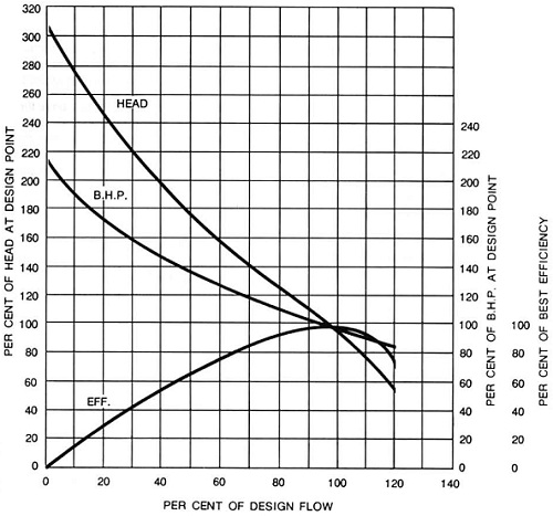 |
| Rice. 3 Axial pump |
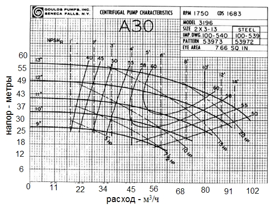 |
| Rice. 4 Operating curve family |
LAWS OF SIMILARITY
Similarity laws express the mathematical relationship between some quantities associated with the characteristics of the pump. They are applicable to all types of centrifugal and axial flow pumps. Laws of the following content:
1. Impeller diameter remains constant: 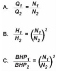
Where Q is the flow m3/hour.
H - head, in meters
BHP - engine power hp
N - pump speed, rpm
2. Pump speed remains constant: 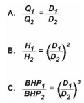
When the performance (Q 1 H 1 BHP 1) is known at some fixed speed (N 1) or wheel diameter (D1) formulas can be used to calculate the performance (Q 2 H 2 BHP 2) at a different speed (N2) or another wheel diameter (D2). Efficiency remains virtually unchanged with speed changes and with small changes in impeller diameter.
Example:
To illustrate the use of these laws, look at Figure 4. It shows the performance of a certain pump at a speed of 1750 rpm with different wheel diameters. Characterization data is determined by actual tests by the pump manufacturer. Now, let's say we have an impeller with a maximum diameter of 13 inches and want to use a belt drive to drive the pump at 2000 rpm.
The similarity laws shown in paragraph 1 above will be used to define a new characteristic with N 1 =1750 rpm and N 2 =2000. The first step is to read the flow, head and power from several points on the 13" diameter curve, fig. 5. For example, one point may be near the point of maximum efficiency where the flow rate is 68 m3 / h, the head is 49 meters and the power is about 20 hp. 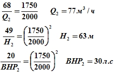
This will be the point of maximum efficiency on the new curve at 2000 rpm. By doing the same calculations for several other points on the 1750 rpm curve, a new curve can be drawn that is close to the pump response at 2000 rpm, fig.5.
Trial and error is required to solve the inverse problem. In other words, suppose you want to determine the speed required for a flow rate of 77 m3/h and a head of 63 meters. You need to select a pre-speed and apply the laws of scaling to convert the required performance to the corresponding 1750 rpm. When you reach the desired speed, in our case 2000 rpm, the point corresponding to 1750 rpm will fall on the curve of the impeller with a diameter of 13 inches.
 |
| Rice. 9 |
SYSTEM CURVES
To calculate impeller diameter and speed, centrifugal pumps have defined and predictable performance curves. The point on the curve where the pump operates depends on the characteristics of the system in which it is installed, this curve is usually called the system head curve or the ratio between flow and hydraulic losses* in the system. A graphical representation is possible, because friction losses are proportional to the area under the curve, the system curve has the shape of a parabola.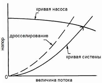
Plotting the system curve and the pump curve together allows you to determine:
1) Where on the curve the pump will operate.
2) What changes will occur if the head curve of the system or the pump characteristic changes.
No static pressure - only friction
When suction and discharge are at the same level (Fig. 6), there is no static head, and, therefore, the system curve starts from zero flow and zero head, its shape is determined only by friction losses. The duty point is at the intersection of the system head curve and the pump curve. The flow can be reduced by adjusting the valve.
positive static head
The parabolic appearance of the system curve is also determined by the frictional losses in the system, including all bends and gates. But in this case, a positive static head is involved. This static head does not affect the shape of the curve or its steepness, but it determines the head of the system curve at zero flow. The duty point is at the intersection of the system head curve and the pump curve. The flow rate can again be reduced by adjusting the gate valve on the discharge pipe.
*Hydraulic losses in the pipeline are the sum of friction losses in the pipe, on valves, in bends, and in other fittings, from losses at the inlet and outlet (inlet and outlet to the pipeline, at the beginning and end, and not to the pump) and losses from changes in pipe diameter, expansion or contraction.
Negative (gravitational) head
In this case, there will be some supply of liquid only due to the gravitational pressure. But in order to achieve high flows, the pump needs to overcome friction losses in the pipeline above the “H” level - the hydrostatic difference between the suction level and the discharge level. In other words, the curve of the system is plotted graphically in the same way as in other cases, taking into account the static head and the pressure to overcome friction, except that the static head is negative here. The system curve starts at negative value and shows the limit feed due solely to gravity. Large feeds require additional work.
Basically, the rise is small friction losses.
The head curve of the system in this case starts from the value of the static head “H” and zero flow. Because friction losses are relatively small (possibly due to large diameter pipes), the system curve is “flat”. In this case, the pump needs to overcome a relatively large static head before it can deliver any flow.
2.11.1 The concept of cavitation. Cavitation reserve
Cavitation is the process of discontinuity of the flow as a result of the formation of vapor or gas bubbles in the liquid flow in the area of low pressure, followed by their condensation in the area of high pressure.
In centrifugal pumps, cavitation occurs on the back side of the impeller blade near its inlet edge (see Figure 2.32), since here the pressure is much lower than the pressure in the suction pipe due to hydraulic losses in the pump inlet and a local increase in the relative velocity of the liquid .
Figure 2.32 - Diagram of the location of cavitation zones in the channels of the impeller of a centrifugal pump, depending on the cavitation mode:
І
–ІІІ
- modes of cavitation; 1
- cavity; 2
- hydrodynamic wake; 3
- drop liquid flow
In the inlet part of the channel, during cavitation, a lot of gas bubbles are formed, which, merging, form a cavity 1
. Next, there is a hydrodynamic trace 2
, in which the concentration of the vapor-gas phase is lower due to an increase in pressure, under the influence of which some of the bubbles condense or decrease in volume. The remaining space of the channels is filled with the fluid flow.
There are three modes of cavitation:
- The initial cavitation mode, in which only small caverns are formed and the cavitation zone, consisting of a cavern and a hydrodynamic wake, does not reach the outlet of the interblade channel and therefore does not affect the operation of the pump.
- The mode of developed cavitation (critical mode), in which the cavitation zone reaches the outlet area of the impeller, as a result of which the magnitude and direction of the absolute velocity changes and the pump head decreases.
- The supercavitation regime is observed when the cavitation zone almost completely covers the outlet area of the channel, as a result of which the flow and pressure of the pump are sharply reduced. This mode is also called lock mode.
Cavitation is accompanied by:
- decrease in flow, pressure, power and efficiency of the pump;
- sound phenomena (noise, crackling, shock) and vibration pumping unit;
- erosion of the channel wall material;
- decrease in the reliability of the pump.
Therefore, cavitation is an undesirable phenomenon in the operation of oil centrifugal pumps.
The phenomenon of cavitation occurs when the energy of the fluid at the pump inlet ( Ev) becomes equal to or less than the elasticity energy of saturated vapors of the liquid, namely:
Where E c - leveling mark of the pump axis; R c - pressure at the liquid inlet to the pump; w c - speed of oil in the suction pipe.
When calculating, as a rule, take zв = 0, and all other elevation marks are counted from the pump axis, so you can write
Where PS- pressure of elasticity of saturated vapors.
Critical NPSH Δ h cr corresponds to the occurrence of a developed cavitation phase in a centrifugal pump, at which a 2–3% head drop is observed. It is determined experimentally by taking partial cavitation characteristics of the pump. A private cavitation characteristic (Figure 2.33) is a graph of the dependence of pressure (or efficiency) on the cavitational reserve at constant flow, speed, viscosity and density of the liquid medium at the inlet to the pump.
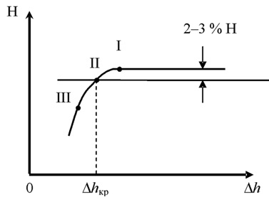
Figure 2.33 - Partial cavitation characteristic of a centrifugal pump:
I- initial cavitation mode; II- critical mode; III- supercavitation mode
Permissible cavitation reserve is the minimum value of the cavitation reserve at which the pump will operate without changing the main technical parameters. Permissible cavitation reserve is determined by the formula:
Where A k - cavitation reserve coefficient, depending on the coefficient of speed of the pump and physical properties liquids. For oil main pumps A k = 1.25; for other pumps - A k = 1.1–1.3.
The value of the critical and permissible cavitation reserve is determined experimentally at the manufacturer's plant when testing the pump on water and is given in the pump's passport characteristics in the form of a graph of the dependence of the cavitation reserve on the pump flow.
When operating on oil and oil products, the value of the cavitation reserve of the pump changes due to changes in the conditions of its suction. The strongest influence on the change in suction conditions is exerted by such properties of oils and oil products as saturated vapor pressure, the presence of soluble and insoluble gases in oil, thermodynamic properties and oil viscosity.
Saturated steam pressure oil and oil products depends not only on temperature, but also on the ratio of the vapor and liquid phases, since when the easily soluble fractions and dissolved associated gases pass into the gaseous state, a drop in the saturated vapor pressure of the remaining liquid oil phase is observed.
Therefore, to determine the pressure of saturated vapor elasticity, it is necessary to use formulas that take this circumstance into account.
The saturated vapor pressure of pumped liquids (in Pa) can be found from one of the following dependencies:
- for oils
- for aviation gasoline
- for stable gas condensate
Where T nk is the initial boiling point of oil or gasoline, K.
Information about the initial boiling point of some oils and the dependence of their saturated vapor pressure on temperature is given in Table 2.13.
Table 2.13 - Reference data for some oils
| Oil |
T, TO |
T nk , K |
PS 10–5, Pa |
Arlanskaya |
293 |
0,637 |
|
Bavlinskaya |
293 |
0,920 |
|
Mangyshlak |
313 |
0,5810 |
|
Mukhanovskaya |
303 |
0,804 |
|
Romashkinskaya |
303 |
0,680 |
|
Tuimazinskaya |
293 |
0,880 |
|
Ust-Balykskaya |
293 |
0,482 |
When pumping gas-saturated liquids under RS their saturation pressure at the pumping temperature should be understood.
Influence of thermodynamic properties of oil such as specific heat capacity, temperature and saturation vapor pressure gradient is expressed in the fact that a pressure drop below the saturation vapor pressure by the same amount in liquids with different thermodynamic properties can lead to the formation of different volumes of vapor.
To take into account the influence of the thermodynamic properties of oil on the NPSH, a thermodynamic correction to the NPSH is introduced, which can be determined by the formula
|
where ∆ ht- thermodynamic correction to the critical cavitation reserve; hS- head corresponding to the saturated vapor pressure of the liquid RS.
Influence of viscosity oil and oil products on cavitation in the pump is affected as follows:
- an increase in the viscosity of the pumped liquid leads to an increase in energy losses at the liquid inlet to the impeller, which in turn leads to an increase in the allowable cavitation reserve;
- an increase in viscosity leads to a slowdown in the growth of steam caverns and, ultimately, to a decrease in the possibility of cavitation.
In general, the effect of viscosity is taken into account by a hydrodynamic correction to the cavitation reserve Δ h n , which is determined by the formula
Thus, the allowable NPSH of the pump when pumping oil or oil product will be equal to
where ∆ h dop.n - permissible cavitation reserve when the pump is running on oil or oil product; Δ h dop.v - permissible cavitation reserve when the pump is running on water.
2.11.2 Calculation of suction capacity of main and booster pumps
When operating pumps at the pumping station, it becomes necessary to check whether the conditions for cavitation-free operation are met. This condition is as follows: in order for the pump to work without cavitation, it is necessary that the actual NPSH of the pump Δ h n was not less than the allowable cavitation reserve Δ h add.n with a given serve, that is:
Where z- the difference between the height marks of the free surface of the liquid in the tank and the axis of the pump, which is called the geometric suction height and is denoted H gv; H gv = z in + z n; z c - height of oil in the reservoir; z n - depth of pump penetration; R- absolute pressure on the oil surface in the reservoir; R c - absolute pressure at the pump inlet;
Head loss during the movement of oil between sections A–A and B–B.
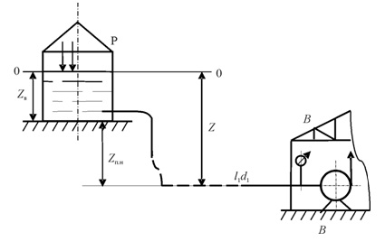
Figure 2.34 - Scheme for determining the cavitation reserve
Subtracting from the left and right sides of equation (2.83) the head
corresponding to the saturated vapor pressure and grouping the terms, we obtain
In general, the sign in front of the NGV can be either "-", as in this case, or "+", if the liquid level in the tank is below the pump axis. Therefore, we finally write the formula for determining the actual cavitation reserve of the pump in the form:
Checking the condition of non-cavitation operation of a group of series-connected pumps is performed for the first pump in the flow.
To check the conditions for cavitation-free operation of the main main pump, the Bernoulli equation is written for the cross section taken on the discharge line of the booster pump and for the cross section at the inlet to the main pump.
2.11.3 Improving the conditions for cavitation-free operation of pumps
Improving the conditions for cavitation-free operation of oil centrifugal pumps, as follows from expressions (2.86) and (2.87), can be done either by reducing the allowable cavitation reserve or by increasing the actual value of the pump cavitation reserve.
To reduce the permissible NPSH of the pump, it is necessary to make such changes in the design of the pump as:
- increase the diameter at the fluid inlet to the impeller D 1 , which in turn can lead to a decrease pump efficiency;
- increase wheel width at fluid inlet b 1 ;
- reduce the thickness of the blades at the fluid inlet to the impeller.
More effective way is the installation of an upstream screw (see figures 2.4 and 2.8) at the liquid inlet to the pump impeller, which is an axial wheel. In contrast to the centrifugal impeller, which consists of more short blades, the screw has several long blades, when passing between which the vapor phase has time to condense and there is still a sufficient part of the blade surface to impart the required pressure to the liquid. Therefore, the upstream screw is capable of passing large volumes of liquid vapor without a significant reduction in the total head. The upstream screw increases the pressure at the inlet to the impeller and thus ensures its cavitation-free operation. In order to improve the working conditions of the screw itself, the thickness of the blade at the liquid inlet to the screw is reduced, and its outer diameter is also increased.
An increase in the actual value of the NPSH (based on formula (2.87)) can be obtained by reducing the pressure loss in the suction line of the pump
and increasing the height of the pump z n.
The normal operation of a centrifugal pump can be ensured under certain so-called cavitation-free modes. Normal operation is maintained only if the pressure at all points of its internal cavity exceeds the saturated vapor pressure of the pumped liquid at a given temperature. This pressure is called critical p cr. If the pressure in the internal cavity of the pump is less than the critical one, then the formation of liquid vapors and the onset of the so-called cavitation are possible. During cavitation, due to the formation of a large number of bubbles filled with liquid vapor, there is a violation of the continuity of the flow. When cavitation bubbles enter the area where the liquid pressure is greater than the critical one (for example, on the surface of the impeller blades), they are destroyed and hydraulic shocks occur in microscopic zones. This leads to local destruction of the impeller metal. The occurrence of cavitation depends on many factors (material and coating on the surface of the impeller, pumping modes). Of greatest importance is the observance of the so-called cavitation-free operating modes of the pump, in which the pressure at the pump inlet pin must be greater than the critical pressure, i.e., the saturated vapor pressure of the pumped liquid. In the passport of each pump indicate the permissible cavitation reserve ∆h kr. For example, for the pump NM 10000-210 ∆h cr = 65m (water column) or p cr = 0.65 MPa. This means that the cavitation-free operation of this pump can only be ensured if the pressure in the inlet (suction) pipe is not less than 0.65 MPa. To ensure cavitation-free operating modes of main pumps, special booster pumps are installed at the head pumping stations, which pump oil or oil products from tanks and supply it under the right pressure on the suction pipes of the main pumps. At the intermediate pumping station, oil or oil product enters the suction pipes from the previous station at a pressure exceeding the permissible cavitation reserve. To ensure normal cavitation-free operation of horizontal booster pumps, they are installed at a mark below zero, i.e., buried booster pumps are used. pumping stations. Instead of horizontal ones, vertical booster pumps are increasingly being used; their normal cavitation-free operation is ensured without deepening below zero.
Where - the value of the allowable cavitation reserve obtained by pumping water; - allowable cavitation reserve of centrifugal pumps when operating on oil; - cavitation reserve coefficient; - coefficient determined by the geometry of the impeller; - thermodynamic correction, taking into account the influence of the thermodynamic properties of the liquid; - correction for the effect of fluid viscosity; - pressure, determined by the minimum pressure at the inlet to the pump; - minimum inlet pressure; - pressure determined by the pressure of saturated vapors.


