Based on the flow and total head specified for the fan or pump, and for the compressor - flow and specific work of compression - the shaft power is determined, in accordance with which the power of the drive motor can be selected.
For a centrifugal fan, for example, the formula for determining the power on the shaft is derived from the expression of the energy imparted to the moving gas per unit time.
Let F be the section of the gas pipeline, m2; m - gas mass per second, kg/s; v - speed of gas movement, m/s; ρ - gas density, m3; ηv, ηp - fan and transmission efficiency.
It is known that
![]()
Then the expression for the energy of the moving gas will take the form:
![]()
where is the power on the drive motor shaft, kW,
![]()
In the formula, groups of values can be distinguished corresponding to the supply, m3 / s, and the pressure of the fan, Pa:
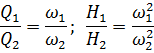
It can be seen from the above expressions that
Respectively
![]()
![]()
here c, c1 c2 are constants.
Note that due to the presence of static pressure and design features centrifugal fans the exponent on the right side can differ from 3.
Similarly to how it was done for the fan, you can determine the power on the shaft centrifugal pump, kW, which is equal to:


where Q - pump flow, m3/s;
Hg - geodetic head equal to the difference between the discharge and suction heights, m; Hc - total head, m; P2 - pressure in the tank where the liquid is pumped, Pa; P1 - pressure in the tank from which the liquid is pumped, Pa; ΔH - pressure loss in the line, m; depends on the section of the pipes, the quality of their processing, the curvature of the pipeline sections, etc.; ΔH values are given in the reference literature; ρ1 - density of the pumped liquid, kg/m3; g = 9.81 m/s2 - free fall acceleration; ηn, ηp - efficiency of the pump and transmission.
With some approximation for centrifugal pumps, it can be assumed that between the power on the shaft and the speed there is a relationship P = cω 3 and M = cω 2. In practice, the exponents y of the speed vary within 2.5-6 for various designs and operating conditions of pumps, which must be taken into account when choosing an electric drive.
The indicated deviations are determined for pumps by the presence of line pressure. We note in passing that a very important circumstance when choosing an electric drive for pumps operating on a high-pressure line is that they are very sensitive to a decrease in engine speed.
The main characteristic of pumps, fans and compressors is the dependence of the developed pressure H on the supply of these mechanisms Q. These dependencies are usually presented in the form of HQ graphs for various speeds of the mechanism.
On fig. 1 as an example shows the characteristics (1, 2, 3, 4) of a centrifugal pump at various angular speeds of its impeller. In the same coordinate axes, the characteristic of line 6, on which the pump operates, is plotted. The characteristic of the line is the relationship between the supply Q and the pressure necessary to lift the liquid to a height, overcome the excess pressure at the outlet of the discharge pipeline and hydraulic resistance. The intersection points of characteristics 1,2,3 with characteristic 6 determine the values of pressure and performance when the pump is operating on a certain line at various speeds.
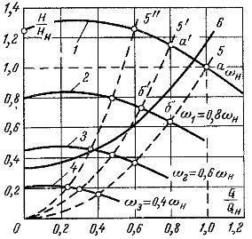
Rice. 1. The dependence of the head H of the pump on its supply Q.

Example 1. Construct characteristics H, Q of a centrifugal pump for various speeds 0.8ωn; 0.6ωn; 0.4ωн, if characteristic 1 at ω = ωн is set (Fig. 1).
1. For the same pump
![]()
Hence,
2. Let's construct the characteristic of the pump for ω = 0.8ωn.
For point b
![]()

For point b"
![]()

Thus, it is possible to construct auxiliary parabolas 5, 5", 5"... which degenerate into a straight line on the y-axis at Q = 0, and QH characteristics for different pump speeds.
The engine power of a reciprocating compressor can be determined from an air or gas compression indicator chart. Such a theoretical diagram is shown in fig. 2. A certain amount of gas is compressed according to the diagram from the initial volume V1 and pressure P1 to the final volume V2 and pressure P2.
Work is expended on gas compression, which will be different depending on the nature of the compression process. This process can be carried out according to the adiabatic law without heat transfer, when the indicator diagram is limited by curve 1 in Fig. 2; according to the isothermal law at a constant temperature, respectively, curve 2 in Fig. 2, or along the polytrope curve 3, which is shown as a solid line between the adiabat and isotherm.

Rice. 2. Gas compression indicator diagram.
The work during gas compression for a polytropic process, J/kg, is expressed by the formula
where n is the polytropic index, determined by the equation pV n = const; P1 - initial gas pressure, Pa; P2 - final pressure of compressed gas, Pa; V1 is the initial specific volume of gas, or the volume of 1 kg of gas at suction, m3.
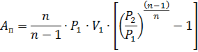
Compressor motor power, kW, is determined by the expression
here Q - compressor flow, m3/s; ηk - indicator efficiency of the compressor, taking into account the power loss in it during a real working process; ηp - efficiency of mechanical transmission between the compressor and the engine. Since the theoretical indicator diagram differs significantly from the actual one, and obtaining the latter is not always possible, when determining the compressor shaft power, kW, an approximate formula is often used, where the initial data are the work of isothermal and adiabitic compression, as well as efficiency. compressor, the values of which are given in the reference literature.
This formula looks like:
![]()
where Q - compressor flow, m3/s; Au - isothermal work of compression of 1 m3 of atmospheric air to pressure Р2, J/m3; Aa - adiabatic work of compression of 1 m3 of atmospheric air to pressure Р2, J/m3.
The relationship between the power on the shaft of a piston-type production mechanism and the speed is completely different from the corresponding relationship for mechanisms with a fan-type torque on the shaft. If a piston-type mechanism, such as a pump, works on a line where a constant pressure H is maintained, then it is obvious that the piston has to overcome a constant average force with each stroke, regardless of the rotation speed.
The power on the shaft of a centrifugal compressor, as well as that of a fan and a pump, subject to the reservations made earlier, is proportional to the third power of the angular velocity.
Based on the formulas obtained, the power on the shaft of the corresponding mechanism is determined. To select an engine, the nominal values of flow and pressure should be substituted into these formulas. Based on the power received, a continuous duty motor can be selected.
Design, principle of operation of a centrifugal pump. Delivery, total head (two-gauge rule), suction lift, efficiency, absorbed and useful power centrifugal pump.
Centrifugal pumps are one of the most common types of dynamic hydraulic machines. They are widely used: in water supply systems, water disposal systems, in thermal power engineering, in the chemical industry, in the nuclear industry, in aviation and rocket technology, etc.
Rice. 1 circuit diagram centrifugal pump:
5 - impeller blade;
6 - guide vane; 7 - discharge pipe;
8 - bearing; 9 - pump housing (support stand);
10 - hydraulic shaft seal (stuffing box);
11 - suction pipe.
On the impeller there are blades (blades), which have a complex shape. The liquid approaches the impeller along the axis of its rotation, then it is directed to the interblade channel and enters the outlet. The outlet is designed to collect the fluid leaving the impeller and convert the kinetic energy of the fluid flow into potential energy, in particular into pressure energy. The energy conversion indicated above must occur with minimal hydraulic losses, which is achieved by a special form of branch.
The pump housing is designed to connect all the elements of the pump into an energy hydraulic machine. A vane pump converts energies due to the dynamic interaction between the flow of a liquid medium and the blades of a rotating impeller, which is their working body. When the impeller rotates, the liquid medium in the inter-blade channel is thrown to the periphery by the blades, goes into the outlet and then into the pressure pipeline.
Centrifugal Pump Feed
The basis for the supply of a centrifugal pump, i.e. the amount of fluid flowing through the impeller per second can be the well-known fluid flow equation: Q = F υ.
For the case under consideration (Fig. 2.5.): QT = (π D 2 - z δ 2) b 2 c m2 (2.11)
where D2 is the outer diameter of the wheel; z is the number of blades; δ2 is the thickness of the blade along the circumference with the diameter D2;
b2 - wheel width on the outer diameter; сm2 is the velocity of fluid exit from the wheel in the meridional direction.
Rice. 2.5. Clear area at the liquid outlet from the impeller
 In equation (2.11), the free sectional area of the wheel on the outer circumference can be expressed:
F = λ π D 2 b 2
where λ is the coefficient of restriction of the fluid flow, taking into account the areas occupied by the ends of the blades.
This coefficient, depending on the number and thickness of the blades, is in the range of 0.92 ... 0.95.
Taking into account the fact that cm 2 \u003d c 2 sinα 2 and
after transformations we get: ![]()
Therefore, the theoretical flow of a centrifugal pump can be represented by the formula: Q T = 0.164 · λ · ψ · D 2 2 · b2 · n * ψ.
From this it can be seen that the supply of a centrifugal pump is proportional to the square of the outer diameter of the wheel, its width, the number of revolutions and the coefficient ψ, which depends on the change in the angles α2 and β2. Limits of change ψ = 0.09...0.13. The actual feed Q is slightly less than QT:
Q = ηO QT ,
where ηO is the leakage coefficient or volumetric efficiency, which takes into account slotted fluid losses through the gap between the wheel and the housing. These fluid leaks are due to the pressure difference between the discharge and intake of the wheel.
Therefore, the amount of liquid flowing through the wheel is greater than the actual delivery of the pump into the pressure line. To reduce leakage, the specified gap is made small - approximately 0.3 ... 0.6 mm. The value of ηO, depending on the design and dimensions of the pump, varies within 0.92...0.98. Thus, the pump flow can be determined from the expression:
Q = 0.164 λ ψ ηO D 2 2 b 2 n. (2.12)
The found value of the flow Q will approximately correspond to the normal flow of the pump at a given head H. In other modes of operation of the pump, the flow will vary depending on the changes in head according to the pump characteristic.
full head, developed by a centrifugal pump, is the sum of the vacuum suction head, the geometric discharge head and the head loss in the pressure pipe. Since the sum of the last two terms is measured with a pressure gauge, we can say that the total pressure developed by a centrifugal pump is the sum of the readings of the vacuum gauge and pressure gauge. If the pressure gauge and vacuum gauge are installed at different levels, then z (the difference in the point marks (connections of the vacuum gauge and the center of the pressure gauge) must be added to the sum of their readings).
 Pump suction head increases with an increase in pressure p0 in the receiving tank and decreases with an increase in pressure rvs, fluid velocity ωvs and head loss hp..ss in the suction pipeline.
If the liquid is pumped from an open container, then the pressure p0 is equal to atmospheric pa. The pressure at the pump inlet RVS should be more pressure pt of the saturated vapor of the pumped liquid at the suction temperature (pc > pt), because otherwise the liquid in the pump will start to boil. Hence, 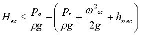
those. suction height depends on atmospheric pressure, speed and density of the pumped liquid, its temperature (and, accordingly, its vapor pressure) and the hydraulic resistance of the suction pipeline. When pumping hot liquids, the pump is installed below the level of the receiving tank in order to provide some support from the suction side, or create overpressure in the receiving container. High-viscosity liquids are pumped in the same way.
centrifugal pump efficiency, like any other mechanism, is the ratio of useful power to consumed. It is denoted by the letter η.
η under no circumstances can be greater than one, because there is no lossless drive. Power losses in the pump are made up of mechanical, volumetric, hydraulic losses.
Mechanical power losses are due to friction in the seals and bearings, as well as hydraulic friction on the surface of the impellers and balance discs. Mechanical efficiency of pumps varies within ηМ = 0.9...0.98.
Volumetric losses in centrifugal pumps are caused by fluid overflowing through the front wheel seal and the shaft sleeve seal. The values of volumetric efficiency η0 for modern centrifugal machines range from 0.96 to 0.98.
Hydraulic losses are associated with hydraulic friction, impacts and vortex formation in the flow path. Smoothly contoured impeller channels, no sharp turns, expansions or contractions, meticulous workmanship internal surfaces flow part provide high hydraulic efficiency of the pump. For modern pumps good workmanshipηГ values range from 0.85 to 0.96
The product η_O∙η_M∙η_G=η gives the total efficiency. A change in the values of the factors also gives a change in the value of the total efficiency. This change is given by the function of the flow in the pump curve.
Net power- this is the energy given to the liquid per unit of time during the operation of the pump. ![]() [W]
[W]
Power consumption is the energy consumed by the pump per unit of time.
The efficiency of any mechanism is the ratio of its useful power to the consumed. This relationship is denoted by the Greek letter n(this). Since there is no such thing as a "lossless drive", n always less than 1 (100%). For circulation pump heating systems, the overall efficiency is determined by the value of the motor efficiency nM(electrical and mechanical) and pump efficiency np. The product of these two values is the total efficiency ntot.
n tot = n M n p
pump efficiency different types and sizes can vary over a very wide range. For wet rotor pumps Efficiency ntot equal to 5% to 54% (high efficiency pumps); for dry rotor pumps ntot is from 30% to 80%. Even within the limits of the pump characteristic, the current efficiency at one time or another varies from zero to a maximum value. If the pump is running with the valve closed, a high pressure, but the water is not moving, so the efficiency of the pump at this point is zero. The same is true for open pipe. Despite a large number of pumped water, no pressure is created, which means that the efficiency is zero.
The greatest overall efficiency of the circulation pump of the heating system is achieved in the middle part of the pump curve. In the pump manufacturer's catalogues, this optimum performance is listed separately for each pump.
The pump never runs at constant flow. Therefore, when calculating pumping system, make sure the pump duty point is in the middle third of the pump curve most heating season. This ensures that the pump operates at optimum efficiency.
Pump efficiency is determined by the following formula:
n p \u003d Q H p / 3670 P 2
np= pump efficiency
Q [m3/h]= Submission
H [m]= Head
P 2 [kW]= Pump power
3670
= constant factor
p [kg/m3]= Density of liquid
The efficiency of a pump depends on its design. The following tables show the efficiency values depending on the selected motor power and pump design (glanded/dry).
Energy consumption of centrifugal pumps
The motor drives the pump shaft, on which the impeller is mounted. An increased pressure is created in the pump and the liquid moves through it, which is the result of the transformation electrical energy into hydraulic. The energy required by the motor is called the consumed energy. P1 pump.
Output characteristics of pumps
The output characteristics of centrifugal pumps are shown in the graph: the vertical axis, the ordinate, means the energy consumed P1 pump in watts [W]. The horizontal axis or abscissa shows the feed Q pump in cubic meters per hour [m3/h]. In catalogs, the characteristics of head and power are often combined to visually demonstrate the relationship. The output characteristic shows the following relationship: the motor consumes a minimum of energy at low flow. As the supply increases, the energy consumption also increases.
Pump characteristics
Influence of motor speed
When the pump speed changes and other system conditions remain unchanged, the energy consumption P changes in proportion to the frequency value n cubed.
P 1 / P 2 \u003d (n 1 / n 2) 3
Based on these considerations, by changing the speed of the pump, it is possible to adapt the pump to the required heat load of the consumer. When the speed is doubled, the feed is increased by the same proportion. The pressure increases four times. Therefore, the energy consumed by the drive is obtained by multiplying by about eight. By reducing the frequency, the flow, the pressure in the pipeline and the energy consumption are reduced in the same proportion.
Constant speed due to design
A distinctive characteristic of a centrifugal pump is that the pressure depends on the motor used and its speed. Pumps with frequency n > 1500 rpm are called high-speed pumps, and those with a frequency n are called slow-moving. Slow pump motors have more than complex structure which means they are more expensive. However, in cases where the use of a low-speed pump is possible or even necessary due to the characteristics of the heating circuit, the use of a high-speed pump may lead to unreasonably high energy consumption.
» understood special device, which serves to move the pumped medium (solid, liquid and gaseous substances). Unlike water-lifting mechanisms, which are also designed to move water, the pump increases the pressure or kinetic energy of the pumped liquid.
Net pump power- the power reported by the pump to the supplied liquid medium. But before moving on to the concept of power, it is necessary to consider two more parameters of the pump: the flow and pressure of the pump.
Pump flow is the amount of liquid supplied per unit of time and is indicated by the symbol Q.
The pump head is the increment of mechanical energy received by each kilogram of liquid passing through the pump, i.e. difference specific energies liquids at the exit from the pump and at the entrance to it. In other words, the head of the pump shows to what height in meters the pump will raise the column of water.
And finally, the third parameter of interest to us is the pump power N. Power is usually measured in kilowatts (kW). The total energy increment received by the entire flow in the pump per unit time, i.e. useful power Np of the pump is defined as
Nп = yQH/102 (kW), where y is specific gravity liquids.
Pump power N - power consumed by the pump - power supplied to the pump shaft from the engine.
The power of the pump is actually the power supplied to it by the electric motor. Circulation pumps installed in household systems have a fairly low power and, as a result, low power consumption. In fact, such pumps do not lift water to a height, but only facilitate its movement further along the pipeline, overcoming local resistances such as bends, taps and bends.
In addition to circulation pumps, pumps for increasing pressure can be mounted in the pipeline system.
When using a circulation pump in the pipeline, the efficiency of the home heating system is significantly increased. In addition, it becomes possible to reduce the diameter of the pipeline and connect a boiler with increased coolant parameters.
To ensure uninterrupted and effective work heating system, you need to perform a small calculation.
Required to define required power boiler - this value will be the base when calculating the heating system.
According to SNiP 2.04.07 " Heating network“Each house has its own heat consumption norms (for the cold season, i.e. minus 25 - 30 degrees Celsius).
for houses with 1-2 floors, 173 - 177 W / square meter is required
for houses with 3-4 floors, 97 - 101 W / square meter is required
if 5 floors or more, 81 - 87 W / square meter is needed.
Calculate the area of the heated premises of your house and multiply by the value corresponding to the number of storeys of your house.
The optimal water consumption is calculated using a simple formula:
Q=P,
where Q is the flow rate of the coolant through the boiler, l/min;
P - boiler power, kW.
For example, for a 20 kW boiler, the water flow is approximately 20 l/min.
To determine the coolant flow in a particular section of the route, we use the same formula. For example, you have a 4 kW radiator installed, which means that the coolant flow rate will be 4 liters per minute.
Next, you need to determine the power of the circulation pump. To determine the power of the circulation pump, we use the rule that 0.6 meters of pump head is required for 10 meters of the route. For example, with a route length of 80 meters, a pump with a head of at least 4.8 meters is required.
You can look at the pump for heating with the required parameters in our catalog.
It should be noted that the calculation presented in the article is for reference only. In order to determine the power of a centrifugal pump for your home, use the advice of our experts or the recommendations of heating engineers.
In order to ensure the constant functioning of the heating system, it is desirable to install two pumps. One pump will operate continuously, the second (installed on the bypass) will be on standby. In the event of a breakdown or some kind of malfunction of the working pump, you can always turn it off and dismantle it from the circuit, and the standby pump will start working. In the case when the installation of the bypass branch of the pipeline is difficult, another option is possible: one pump is installed in the system, and the other is in reserve in case of failure or breakdown of the first.
Pump power loss and pump efficiency.
Due to losses inside the pump, only part of the mechanical energy received by it from the motor is converted into the energy of the fluid flow. The degree of use of the energy of the engine is measured by the value of the total efficiency.
Efficiency - the efficiency of the pump - is one of its main quality indicators and characterizes the amount of energy loss.
Efficiency = Np / N
Pump Loss = 1 - Efficiency
By analyzing the causes of losses in the pump, you can find ways to increase its efficiency.
All types of losses are divided into three categories: hydraulic, volumetric and mechanical.
Hydraulic losses - part of the energy received by the flow from the pump wheel is spent on overcoming the hydraulic resistance when the flow inside the pump leads to a decrease in the head.
Mechanical losses - part of the energy received by the pump from the engine is spent on overcoming mechanical friction inside the pump. In the pump, there are: friction of the wheel and other parts of the rotor on the liquid, friction in the seals and friction in the bearings. Mechanical losses lead to a drop in pump performance.
Thus, the total efficiency of the pump is determined by the hydrodynamic improvement of the flow path, the quality of the internal seal system, and the amount of mechanical friction losses.
The selection of the required pump is carried out according to the catalog. Of the selected pumps, preference is given to those that consume less power and have a higher efficiency. After all, the power and efficiency indicators further determine the cost of electricity during the operation of the pump.


