Electronics engineers have a famous saying: “Electronics is the science of contacts.” It can be said, with a fairly large degree of coincidence, that plumbing systems also obey this statement.
Here, too, a lot depends on the quality of the connections and the condition of the pipelines. At the same time, there is one significant difference - if you are going to implement a well connection scheme, you must know, at least in general terms, both the principles of constructing the well itself and the type and design of the pump used.
Make sure your water lines follow the science of contact too.
Thus, let’s look at what pumps we have at our disposal in general according to their design:
- horizontal or vertical - depending on the orientation of the axis of rotation of the working shaft;
- with outriggers or internal supports;
- with axial or lateral water inlet;
- single-stage or multi-stage - depending on the number of water supply stages;
- sectional - each stage has a connector at the end;
- with end or axial connector;
- With protective coating inside or without;
- submersible - its location is below the water level;
- semi-submersible - the device itself is below the water level, and the engine is above;
- self-priming - automatically and independently fills the supply pipeline;
- adjustable – able to independently regulate the volume of water supply;
- sealed - contact of water with the atmosphere is excluded.
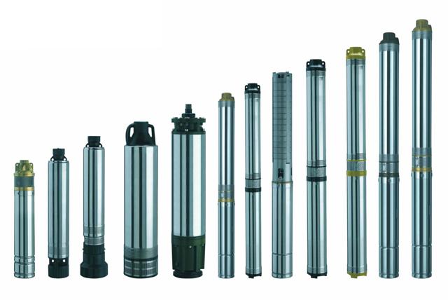
There are other design characteristics, but judging by the variety of design solutions presented, we can conclude that the market offers a huge number of pumps for.
But most often used:
- vertical - they are perfect for the application in question;
- monoblock - simplicity is needed here, taking into account the level of impurities;
- with internal supports;
- with axial entry - also according to the casing pipe configuration;
- single-stage – based on the principles of simplicity;
- with end connector;
- using internal protection surfaces;
- submersible, and
- sealed.
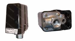
Submersible
One of the most famous submersible pump schemes is shown in photo “A”.
Here:
- A – pump part;
- B - filter;
- C—electric motor;
- D – pipe thread 1 inch;
- E – capacitor box;
- F – this model has a maximum internal case diameter of 105 mm.
Electrical connection
The schematic diagram for connecting such a pump looks like this:
- A – water heater;
- B – storage tank for 40-50 liters;
- C – pressure switch – for protection against overpressure;
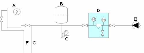
- D – coarse filter;
- E – placement of the device in the well;
- F – pipeline hot water to the house;
- G – pipeline cold water to the house.
Complete connection diagrams
There are several connection systems. We present some of them, the most typical.
Connection using a coffer chamber
If you decide to make a caisson chamber, then proceed with it last stage well equipment.
In this case, the complete connection will look like this:
- A – caisson chamber;
- B – constant water level;
- C – safety rope;
- D – pump;
- E – dry running sensors – pay attention to these very useful auxiliary elements systems, they are not installed often, but sometimes they are indispensable when analyzing the progress of work;
- F – well casing;
- G – control system electrical cable;
![]()
First of possible options connections - with caisson (see description in text)
- H – control panel;
- I – pressure switch – another important element controlling the system;
- J – fitting for five inputs;
- K - pipe head - we advise you to pay attention to the careful layout and condition of the head Special attention;
- L – water drain valve, as an element of the protective system;
- M – hydraulic accumulator;
- N – pressure gauge – it is necessary to know the pressure in the system at all times;
- P – of this circuit – the filter is already at the exit from the system;
- Q – check valve.
Connection with emphasis on the hydraulic accumulator
Please note that in the following figure, the filter is installed in the middle and you are using water freeze protection:
- 1 – well head;
- 2 – electrical cable;
- 3 - galvanized pipe - corrosion protection is very important for devices of this kind;
- 4 – safety rope;
- 5 – sealed cable coupling;
- 6 – adapter;
- 7 – pipe;
- 8 – cable ties;
- 9 – check valve;
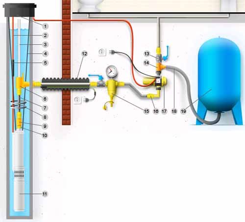
- 10 – nipple;
- 11 – borehole pump;
- 12 – frost protection;
- 13 – shut-off valve;
- 14 – tee;
- 15 – main filter;
- 16 – adapter;
- 17 – electronic automation unit;
- 18 – wiring;
- 19 – hydraulic accumulator.
Extreme attention to fittings
Another option demonstrates the most careful attitude to the entire connecting system, recalling that pipelines are also the science of contacts.
We pay attention to the sensor used in working and “dry” states:
- A - position of the sensor in the operating position of the pump, when there is enough water in the channel;
- B – well head;
- C – horizontal of the upper ground level;
- D – water heater;
- E—hydraulic accumulator;
- F – total depth;
- G – dynamic, constantly changing level;
- H – minimum distance from the edge;
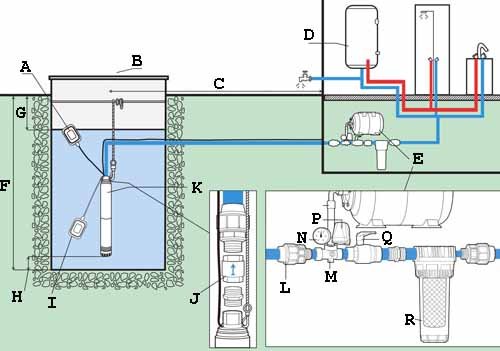
- I – sensor position when an emergency stop occurs due to lack of water, “dry” mode;
- J – position of the check valve, pay attention to the fitting system;
- K – submersible pump with float;
- L – coupling;
- M – fitting for 5 outlets;
- N - pressure gauge;
- P – pressure switch;
- Q – ball valve;
- R – pre-filter.
Surface pump connection
Introducing the connection of the surface pump:
- 1 – control system;
- 2 – power cord and plug;
- 3 – power cord and socket;
- 4 – circuit breaker– a mandatory element for protection against overloads and, nevertheless, maintaining the system in working order;
- 5 – power socket, the proposed circuit operates from a standard network of 220 V and 50 Hz;
- 6 – well;
- 7 – input strainer;
- 8 – check valve;
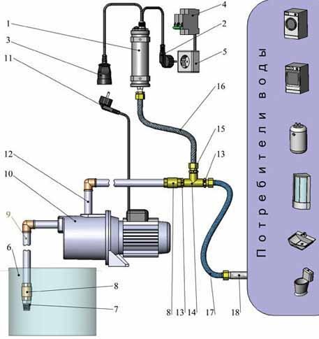
- 9 – suction pipeline;
- 10 – surface pump;
- 11 – pump power cord and plug;
- 12 – discharge pipeline;
- 13 - nipple;
- 14 - tee;
- 15 – transition nipple;
- 16 – flexible liner;
- 17 - eyeliner;
- 18 – pipeline to consumers.
Helpful advice!
When choosing a pump, we advise you to focus on the following criteria: its purpose, performance and required height of water rise, type of suction hose, if it is a surface pump - the shape and diameter of the internal section can reduce the performance of the pump, in what conditions the operation will take place - indoors or outdoors air.
conclusions
There are many options for connecting pumps to supply water from a well. Without experience, setting up these circuits with your own hands, even if there are instructions, will be very difficult. Let us take into account that the cost of possible mistakes is also too high.
Offer all the work to professionals. However, this does not exclude the need to know in detail all the nuances of the processes taking place, so be sure to watch the video in this article more than once.
Own water supply personal plot this is a huge plus, since it does not require much effort from the owner to obtain water for irrigation or water supply to the house. After installing a well or well in the yard, a system is needed to lift the liquid, as well as maintain pressure in the water supply on the way from the well to the house. Because of their ease of maintenance and unpretentiousness, submersible pumps, also called deep or borehole pumps, are installed in the well. From the name it becomes clear that the unit is completely in the water and raises it to the surface. In this article we will talk about how to connect a submersible pump to the network and water supply system with your own hands.
What do you need to prepare?
For uninterrupted supply, automation is needed that will monitor the water supply system and trouble-free operation.
The minimum kit for supplying water from a well or well consists of:
- deep-well pump;
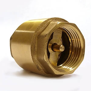
- check valve;
- float with sensor;
- pressure switch;
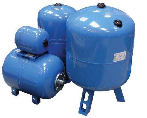
- hydraulic accumulator tank;
- electronic control unit.
Let's consider the purpose of these elements.
The pump is the main power element that lifts water from the well. A check valve is a bypass membrane that is installed directly at the outlet of the power unit, preventing the reverse flow of liquid from the pipe.
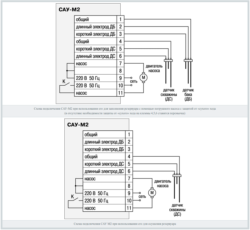
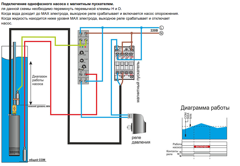
A float sensor is an automation element that monitors the water level in the well. It depends on its position whether permission to start the engine will be given or not. Also often, instead of a float, an electrode level sensor is installed. The sensor connection diagram is provided below:
The pressure switch is another element of automation that directly controls the start of a submerged unit and responds to changes in pressure in the water supply.
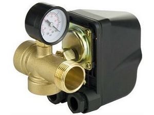
A hydraulic accumulator is a passive system for maintaining pressure in a pipe, smoothing out sudden surges and pressure drops. Works in conjunction with a pressure switch. Extends the life of the pump by increasing the time the engine is turned on and off by accumulating water in the reservoir.
We’ve sorted out the elements of the system, now let’s talk in more detail about how to connect a submersible pump to automation.
Procedure for installing a water pressure system
The location of the devices must provide access for maintenance and control of the operating mode. It is imperative to provide for the ease of replacement of non-working parts. Take care in advance about protection from precipitation and freezing. To connect the submersible pump to the electrical network, you must use a special cable marked VPP or KVV. The insulation of these wires is designed to last for a long time in water, without loss of flexibility and insulating properties. The imported analogue is labeled AQUA RN8.
We recommend connecting the well pump to electricity through, which is necessary to monitor the insulation of the included devices and cable. After all, a problem identified and resolved in time means a saved budget and nerves for the head of the family.
To install the pump and run water through the pipes we will need:
- the water-lifting unit itself;
- special tank - hydraulic accumulator;
- pressure switch, selected for the capacity of the hydraulic accumulator tank;
- American coupling for connecting the pressure switch to the hydraulic accumulator;
- collet coupling, for changing from size to size;
- brass adapters;
- fitting, plastic pipes, FUM tape.
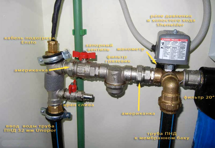
As a rule, the installation and connection of a submersible pump begins with tying up the hydraulic accumulator and installing equipment on it. All stages of assembly are presented in order in the photo:
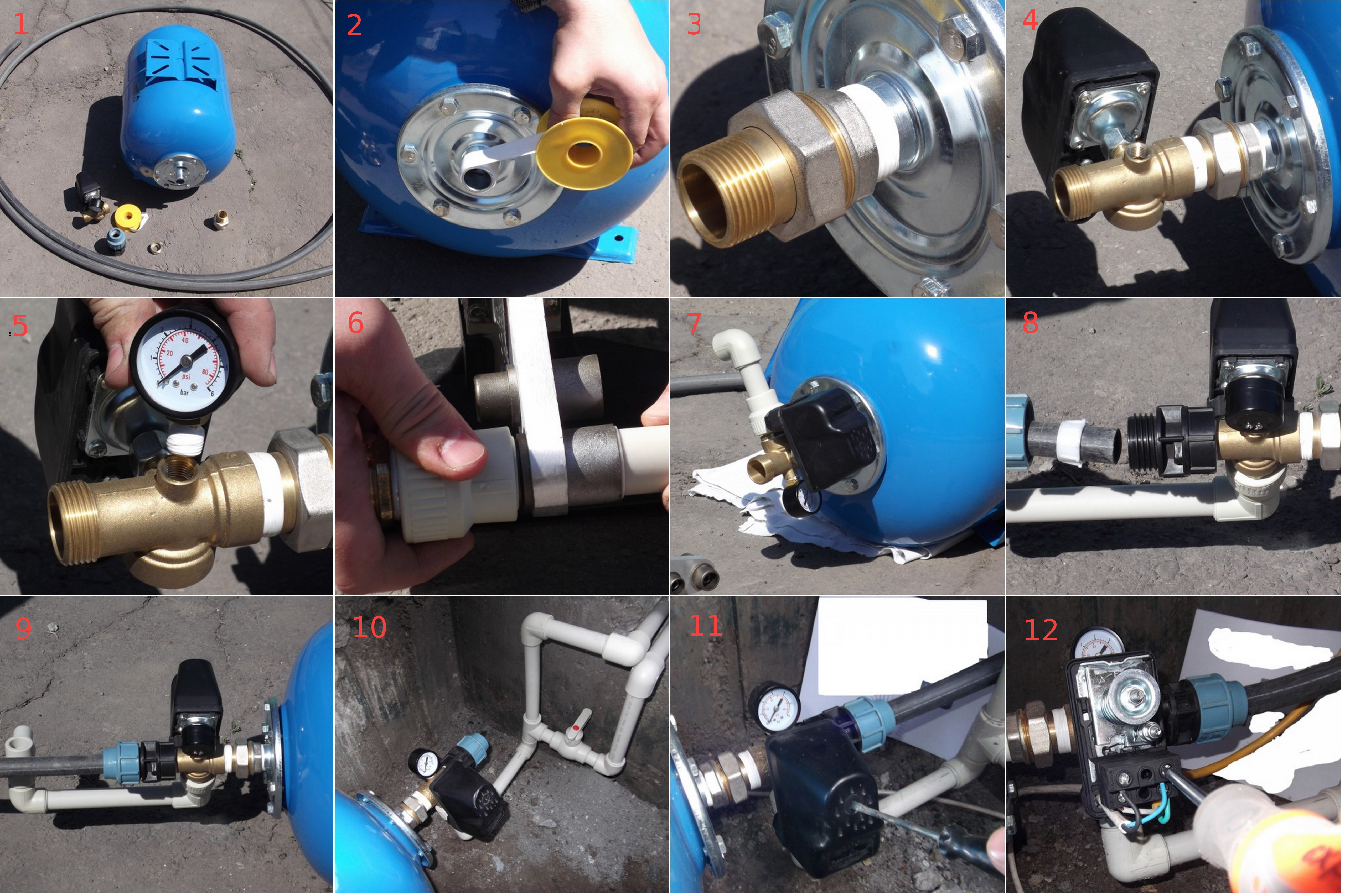
The first stage is the preparation process. In the second picture we use FUM tape to wind threaded connection. Next, we install the “American” connection, which allows us to further produce simple assembly and disassembly. The fourth and fifth pictures show the installation of a pressure switch and pressure gauge for visual monitoring of the process in the system. After this stage, the installation process of the outgoing elbow from PVC pipes to the tee with sensors. The eighth and ninth photos show the installation collet clamp and pressure water supply pipe. The tenth picture shows the installed group connected to the water supply. Well, the last steps are opening and connecting to the relay unit.
If your system consists of one automation unit, a pressure sensor, then at the terminals of this device designate input "LINE" and output "MOTOR". That is, the input from the “LINE” socket and the connection of the “MOTOR” submersible pump. More advanced automation consists of an electronic unit.
The pump start control unit ensures an uninterrupted supply of water to the system, protecting the engine from running dry, reacting to the presence and level of water around the pump. The block produces smooth start and smooth stop, prolonging the motor life of the engine, monitors the mode of its operation.
Control unit diagram:
Dry running is the operation of the engine without a sufficient amount of water or without it, which causes overheating of the working windings of the engine, destruction of the insulation, and failure of the motor. All because the water is in deep-well pumps plays the role of a cooler, because passes through it and cools the body.
Electrical connection of submersible pump and heating cable
The well pump and heating cable must be connected to the electrical network using a circuit breaker (3-6A). It is also necessary to use a differential current switch (RCD or differential circuit breaker with a leakage current of 10 mA).
We can recommend the following manufacturers: Schneider, Merlin Gerin, ABB (switches Russian production or from China it is better not to take). For external laying of the cable supplying the pump, it is recommended to use a copper three-wire cable VVG with a cross section of 1.5 sq. mm. The depth should be at least half a meter (in order to prevent damage to it). When laying cables, use plastic corrugation(red or orange color). On top of the cable, you need to lay a mechanical protective layer of brick or metal, brick (or place the cable in a plastic pipe). Above the protective layer you need to lay a bright signal tape.
It is recommended to take a photo or drawing of the cable routing diagram. Then from the outside well rings(or in another place, but always where water cannot reach) you should fix the outlet into which the pump will be turned on. The socket must have a cover and a moisture protection rating of Ip 44-Ip54. Of course, care should be taken to ensure proper grounding. Control submersible pump carried out by means of a pressure switch, which is installed on the manifold (to which a pressure gauge is then connected and damper tank).
The most reliable is the electromechanical relay. A good option it may be possible to use a combined relay equipped with protection against "dry running" (for example, the cost of such a Schneider brand relay is 1500 rubles). The use of a more expensive combined relay - Pedrollo (price 1800-2000 rubles) will allow you to do without a damper tank, since thanks to it the pump start-up becomes smooth.
However, water supply with a damper tank has its advantages. In particular, if a tank with sufficient volume is used, this reduces the number of pump starts, thus ensuring the accumulation of a reserve volume of water (a third of the tank volume) in case of a power outage.
It is considered most appropriate to install a damper tank of 50 or 100 liters. When a pumping station is used, the mandatory elements of the water intake head of the well part of the water supply system must be a strainer and a check valve. The pump (with proper automation) and the damper tank are located in the house as one unit.
Diagram 9. Connection pumping station supplying water to the house.


