The autonomous water supply system, which has already become familiar to many, will perform its functions uninterruptedly for a long time only when an expansion tank is present in its design. This fairly simple multifunctional device is available in various modifications. To choose the right equipment for your system, you need to accurately understand the principle of its operation and understand the main types of devices.
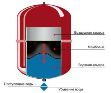
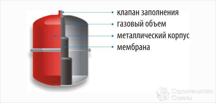
Let's consider the design of the device. Most often this is a closed membrane-type device. A rubber membrane divides the container into two chambers. The first contains air, the second contains water. Once activated, the pump begins to supply liquid to the water chamber. It fills and compresses the air. The amount of air in the tank decreases and the pressure increases. The moment it reaches the set value, the pump turns off.
As water from the tank is used for household needs, the volume of the air-filled chamber increases and the pressure, accordingly, drops. When it reaches the minimum permissible value, the pump starts up again. The cycle automatically repeats. The operating pressure range is selected by the user, the device settings are extremely simple.
The tank can be equipped with a pressure gauge, which will allow you to monitor the pressure in the system. The device performs several functions:
Protects pumping equipment from rapid wear, preventing frequent switching on/off of the device.
- Stores a certain amount of water, which allows you to use the water supply for some time after a power outage.
- Protects the water supply from water hammer, which can occur if air enters the pipeline or during voltage surges in the electrical network.
There are two types of expansion tanks on sale. The first is equipment with a stationary diaphragm rigidly fixed inside the tank. This significantly simplifies the design of the device and reduces the cost of its production. But at the same time, a rigidly fixed diaphragm also has disadvantages. First of all, the liquid contained in the water chamber comes into contact with the walls of the tank. This can lead to rapid corrosion of the container. Despite the fact that the inner surface of the device is coated with a special protective composition, it is rust that causes the device to fail.
Another disadvantage is the inability to replace the membrane if necessary. As soon as it deteriorates, the device will have to be replaced.
It must be admitted that the service life of this type of device is short. Expansion tanks with a replaceable diaphragm are more durable and reliable. An old element can easily be replaced with a new one through a special flange, which is located on the device body. Things happen a little differently with large devices. The membranes of such tanks are additionally secured to the nipple at the rear, which must be taken into account when changing the diaphragm.
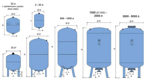
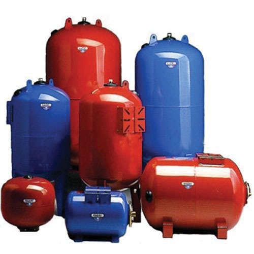
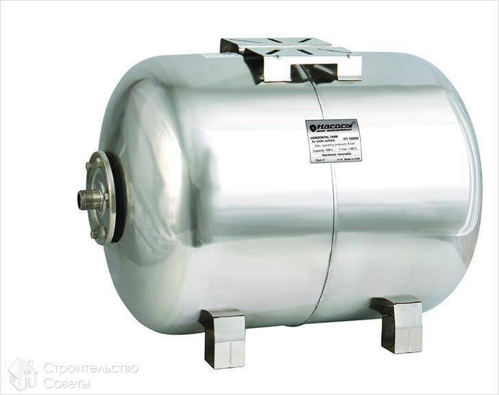
An advantageous feature of tanks with a replaceable membrane is that water is poured inside the rubber diaphragm. Thus, its contact with the walls of the tank is impossible, which reliably protects them from corrosion. In addition, contaminants cannot enter the water and it remains clean. Thus, the service life of membrane tanks of this type is much longer, but the cost is also higher. Both modifications are produced in horizontal and vertical versions.
Main characteristics membrane tank, which determines the choice of device is its volume. On average, it can vary from 20 to 100 liters. The main rule: the capacity of the device should be sufficient to satisfy all the household needs of the home owner. Therefore, when determining the volume of a membrane tank, the following factors must be taken into account:
Number of water points. This includes not only taps and shower heads, but also household appliances that use water, such as a washing machine or dishwasher.
- The number of residents who will use the water supply.
- The manufacturer’s maximum permissible number of pump starts and stops per hour.
- The likelihood of simultaneous operation of several water points.
When choosing the required volume of a membrane tank, you need to take into account a few more points. The smaller the container, the more often pressure surges will occur within the system. In addition, pumping equipment will turn on/off much more often than when working with a large tank. Therefore, other things being equal, it is worth choosing a larger expansion tank if possible.
If during operation it turns out that the capacity is small, you can install an additional tank. In this case, no dismantling work will be necessary; the new device is installed next to the existing one. After its installation, the size of the tank will be determined as the total volume of both tanks. When purchasing, you should not try to save as much as possible; it is better to purchase a high-quality device from a trustworthy manufacturer.
If you choose a model with a replaceable diaphragm, you should inquire about the cost of consumables. Some not the most conscientious manufacturers offer them at a clearly inflated price, which is very unprofitable.
Diaphragm tank – necessary element autonomous water supply. Its installation allows you to make the operation of the water supply system long-lasting, comfortable and uninterrupted. published
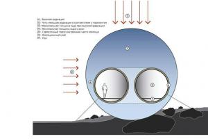
To ensure the normal uninterrupted functioning of centralized water supply systems, structures such as water towers or other types of storage tanks are used.
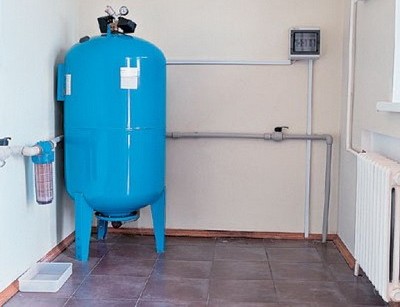
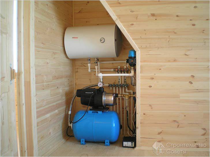
Despite the fact that in autonomous systems Since the volumes and required water consumption are much smaller, it is also impossible to do without an installation of this type. The role of a kind of water tower is played by an expansion tank for water supply, which, thanks to its small sizes can be installed in any heated room.
Installing this structural element water supply systems allow you to solve several technical problems:
- Creation of a certain reserve of water under pressure, ensuring supply to any water intake point. The average volume of the expansion tank (25-30 liters) is capable of providing flow per point for 2-3 minutes.
- Protection of network elements from possible water hammer, which can be caused by air entering the system or significant changes in the power supply network, which can cause unstable operation of pumping equipment.
- Reducing the number of pump on-off cycles, which can significantly increase its operating life.
|
|
Operating principle and design of the expansion tank
For the installation of autonomous water supply systems, closed expansion tanks of the membrane type are mainly used. Structurally, such a tank is a sealed container divided by a rubber membrane into two parts - water and air. The air in the chamber is under a certain pressure, providing the necessary water pressure.
The principle of operation of the device is quite simple. Water supplied pumping unit, fills the container, while the stretching membrane reduces the volume of the air chamber, while the pressure in it increases significantly. After the pressure is in expansion tank water supply reaches the set limit, the automation stops the pump.
The pressure created by the air chamber makes it possible to ensure water flow at all points of consumption, while the automatic pump starts working when the pressure drops below the set value. Depending on the operating conditions, you can adjust the pressure parameters for turning on and off the pumping equipment. A membrane-type tank is capable of providing stable, reliable water flow even in multi-storey residential buildings.
Types of expansion tanks
The membrane expansion tank for water supply is usually available in two modifications (depending on the type of membrane used):
- Models with a stationary membrane are considered cheaper. A diaphragm of this type is rigidly mounted in the body of the unit; it is durable with significant elasticity. When choosing such a modification of the tank, it is worth remembering that if the diaphragm breaks, the entire installation will have to be changed; it cannot be repaired or restored. To protect the inner surface of the tank, painting is used; its quality depends on the manufacturer, but you should not expect exceptional durability from products whose cost is low. On sale you can find models of vertical and horizontal type installation
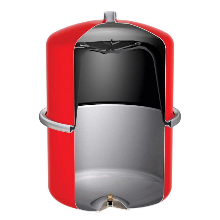
- Tanks with replaceable membrane are considered the more preferable option. Such a unit has a collapsible body (equipped with a twist-off flange), and the membrane has the shape of a bag, which ensures that there is no contact of water with internal surfaces tank. This ensures a longer working life of the device. Selection of expansion tank of this type should be based not only on the total cost of the product, but also on the price of components (membranes). Quite often you can find inexpensive models, the membranes for which are very difficult to find or their cost is quite high. Therefore, when purchasing, pay attention to this point.
How to choose an expansion tank without mistakes
The cost of components is not the only criterion that is worth paying attention to.
The main indicator is the volume of the device, which is selected depending on the following indicators:
- The maximum possible number of start-off cycles for the operating pumping equipment. Remember that the smaller the tank capacity, the more often the pump will be turned on, which can significantly affect its durability and performance.
- The number of water intake points, it is worth considering not only the bathtub, shower cabin, washbasin, but also household appliances(washing machine or dishwasher, etc.).
- The total number of people living in the house.
- Possibility of simultaneous water selection from several points.
All these parameters have an impact on the optimal capacity of the expansion tank.
Experts recommend using the following indicators as approximate data:
- If the pump capacity does not exceed 2000 liters per hour, and no more than 2-3 people live in the house, it is advisable to opt for a unit with a capacity of 20-24 liters, for example, a Reflex expansion tank.
- If it is necessary to meet the needs of a larger family (up to 8 people), a unit with a capacity of 50 liters is installed. In this case, the pump capacity should not exceed 3500 liters per hour.
- If greater water consumption is required, expansion tanks are used, the volume of which reaches 100 liters.
Advantage modern devices is that it is now possible to connect additional containers to increase the volume of expansion devices. That is, if the number of family members increases or there is a need to increase water consumption due to other circumstances, it is possible to connect an additional tank without disconnecting the already installed one. In this case, the total capacity of the installations will be equal to the total volume of all devices.
So, to meet the needs of a large family, you can purchase Gilex expansion tanks for water supply, with a capacity of 25 liters.
Experts do not advise giving preference to cheap installations from dubious manufacturers. Saving now can lead to overspending in the future. It is best to give preference to products famous companies, at the same time, make sure that you are not sold counterfeit products under the guise of products from popular brands.
Rules for installing expansion tanks
According to the type of installation, horizontal and vertical tanks are divided. Differences in technical specifications such models do not, this category simply must be taken into account during installation and connection. Installing an expansion tank for water supply, in principle, is not particularly difficult; it can be done independently (if you have experience in installing water supply networks).
But during installation it is necessary to take into account a number of rules:
- The unit is installed in such a way that access to it is provided for repair and maintenance work. Therefore, when choosing, it is worth considering the size of the room in which the tank will be installed.
- Connections to pipelines should be made using quick-release threaded fittings (American), this will provide the ability to disconnect from the network if necessary.
- The connected pipeline must have an equal or larger cross-section than the inlet pipe.
- The body of the expansion tank must be grounded; this will avoid electrocorrosion processes, which can significantly shorten the life of the device.
- There should be no devices between the pumping equipment and the tank that can increase the hydraulic resistance of the network.
Installing an expansion tank can significantly improve efficiency autonomous water supply. But it is worth remembering that competent selection and installation, in compliance with technological requirements, play a huge role.
If you do not have enough experience in these matters, then you should entrust their solution to a professional who can take into account all the nuances and install the most optimal model of the expansion tank. At the same time, do not try to save money on this unit; only high-quality certified installations can serve you for a long time without breakdowns and expensive repairs.
E. Polyakova
The task of any membrane tank - be it an expansion tank, a hydraulic shock compensator or a hydraulic accumulator - is to ensure reliable, safe and long-term operation of the elements engineering system. The completeness of its solution depends on how correctly the “membrane” is selected and installed.
You can subscribe to articles at
Place of the tank in the heating system
The function of the expansion tank (expansion tank) in the heating system is to compensate for the increase in water volume due to its thermal expansion.
The pressure at the point where the device is connected to the system is always equal to the static pressure at a given point at the existing temperature. It is very simple to prove this: if we assume that the pressure at the tank connection point changes, then we will have to admit that the volume of coolant in the tank has also changed. But this cannot be, because... take excess coolant into closed system nowhere, and he also can’t disappear without a trace. However, this rule only applies to systems with one expansion tank.
Thus, the operating parameters of all other elements of the heating system, the required initial pressure in the tank and its volume depend on the location of the expansion tank.
When choosing the location for connecting the expansion tank, remember that the higher the pressure in the heating system, the less likely it is to become airborne.
On rice. 1 There are several options for connecting a membrane tank to a heating system with the following height parameters:
. the excess of the top point of the system over the bottom ( H) - 10 m;
. The heat generator and safety valve are located 2 m above the lowest point of the system ( h 1);
. The expansion tank is placed 1 m above the point of its connection to the system ( h 2);
. static pressure at the lowest point of the system is 15 m of water. Art.
If the membrane tank is connected to the system immediately after circulation pump(scheme b), you should check that an anti-cavitation pressure reserve is maintained in front of the pump.
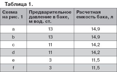
At the remote flags on rice. 1 the calculated values of operating pressure at characteristic points of each system are indicated (in m of water column).
Setting value safety valve accepted 33 m water. Art., pump pressure - 6 m of water. Art., system capacity - 200 l. The difference between the maximum and minimum coolant temperatures is 80 °C.
IN table 1 The calculated characteristics of membrane tanks for circuits with their different connections are given.
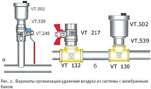
The coolant must enter the membrane tank from above. In this case, there is no chance of air getting into the liquid compartment of the tank. If this requirement cannot be met, it is recommended that the following rules be followed:
. the refill point should be as close as possible to the tank connection point;
. When filling the system with coolant, it is not allowed to use automatic air vents to bleed air (they must be closed).
. Air must be removed from the system through the fittings with taps provided for this purpose (Fig. 2a) or combined taps with drainage and manual air vent (Fig. 2b);
. If possible, use membrane tanks that have an upper pipe for connecting the air vent to the liquid cavity.
Tank selection
It is recommended to determine the sufficient volume of the membrane expansion tank using the formula:
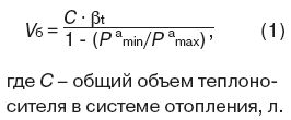
Includes the volume of water in pipes, boiler, radiators and other elements of the system. This indicator is calculated based on the actual capacity of each element of the system; P a min - initial (setting) absolute pressure in the expansion tank, bar; P a max - maximum absolute pressure possible in the expansion tank, bar.
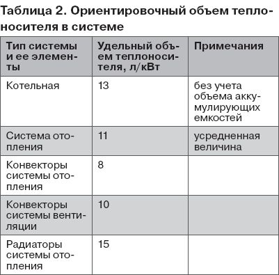
With a certain error, the value of the coolant volume in the system can be selected from table 2. When making calculations at the feasibility study stage, it is allowed to assume a specific capacity of the heating system of 15 l/kW.
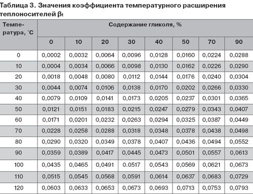
Values of the coefficient of thermal expansion of the coolant β t, corresponding to the maximum difference in water temperatures in an idle and operating system, it is recommended to take according to table 3.
The setting absolute pressure is calculated using the formula:

Absolute maximum pressure possible in the expansion tank:
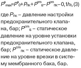
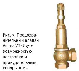
As the analysis shows formula 1, optimal choice The volume of the expansion membrane tank is directly related to the correct setting of the safety valve (according to SP 41-101-95 “Design of Heating Points”, this is a mandatory element for the expansion tank). Usually it is set to a pressure that exceeds the permissible value for the most vulnerable element of the system by 10% (taking into account the difference in height of the valve and the protected element). Therefore, for heating systems it is recommended to use valves with the ability to adjust the setting pressure. In addition, the valve must have a forced opening (“undermining”) device to periodically check its performance and to avoid sticking of the spool. An example of such a valve is shown in rice. 3.
Installing an expansion tank of insufficient volume or incorrect installation can cause the heating system to malfunction and even fail.
The tank setting pressure should not be lower than the hydrostatic pressure at the center of the tank by more than 1 m of water. Art. (0.1 bar). Otherwise, already in the process of filling the system, the useful volume of the tank will be filled with coolant, and with subsequent heating and expansion of the liquid, a smaller volume will be provided than necessary. In other words, if the set (factory) pressure in the tank is 1.5 bar, then the system must be filled to a pressure at the center of the tank that does not exceed 1.6 bar. If according to the project it is necessary to install a higher hydrostatic pressure in the system, then for this, before installing the tank, it is necessary to increase the pressure in it using an air pump.
A certain amount of coolant in the tank, ensured that it is “under-pumped” to hydrostatic by 1 m of water. Art., is necessary in case cooling of the filled coolant occurs. For example, if the system was filled during the day at a water temperature of 20 °C, and the boiler was not started for some reason, when the coolant cools at night, its volume will decrease, which can lead to a vacuum at the upper points of the system and intensive air suction through the air vents.
In two identical systems that differ only in the type of coolant, a larger expansion tank will be required in the system that uses a glycol-based antifreeze coolant (ethylene or propylene glycol). After all, the expansion coefficient of glycol solutions is slightly higher than that of water.
Thus, when switching from a water system to a glycol system, it may be necessary to replace the tank with a larger one or install an additional “membrane”.
A signal that the system needs a larger tank is the frequent operation of the safety valve.
The diameter of the supply line to the membrane expansion tank must be no less than calculated using the following formula:

Tying examples
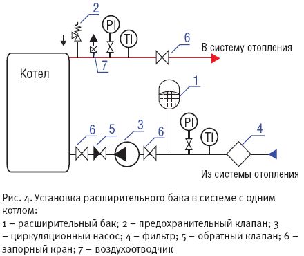
On rice. 4 shows the option of installing an expansion tank in a system with one boiler. In this case, the expansion valve is located on the return pipeline of the system, which allows it to be operated at a lower coolant temperature than if it were installed on the supply line. This solution allows you to extend the service life of the device. Connecting a tank to the pump suction pipe protects the pump from cavitation.
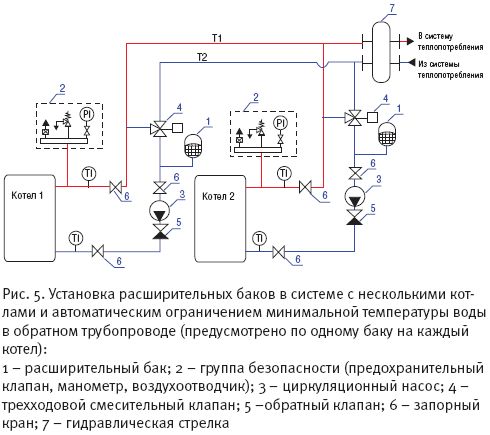
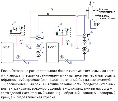
On rice. 5- installation diagram of expansion tanks in a system with several boilers and automatic limitation minimum temperature water in the return line. There is one expansion chamber per boiler. The capacity of each of them must be no less than that calculated for the entire system, i.e. if according to calculations she needs a tank with a capacity of 80 liters, then the capacity of each of the installed devices should be the same. This is due to the fact that when operating at reduced power, when the burner of one of the boilers is turned off, the corresponding circulation pump also turns off and the three-way valve closes. In this case, there is no water circulation through the disconnected boiler, and the expansion tank installed on this boiler is isolated from the rest of the system. The expansion chamber remaining in operation must provide compensation for the expansion of the coolant throughout the entire volume of the system. This provision is also true when using two-way valves that perform the function of blocking boilers.
A system with several boilers and automatic limitation of the minimum return water temperature may have one expansion tank. In this case, it must be mounted as shown in rice. 6.
Membrane tanks for hot water supply
The main difference between membrane tanks for water supply is that the water in them should not come into contact with the walls of the housing, as is allowed in heating systems. Therefore, they always use a membrane chamber type(in the form of a bag). In addition, the membrane material of water supply tanks is subject to increased requirements regarding the permissibility of contact with food liquids.
Today it is unthinkable to imagine a house without a water supply system. But sometimes there are cases when water cannot always reach one or another water point. Then a hydraulic accumulator comes to the rescue, regulating the pressure in the network. Next we will talk about which scheme for connecting a hydraulic accumulator to a water supply system is effective.
Hydraulic accumulator device
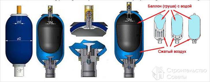
For normal operation of the water supply system in the house, in some cases, a hydraulic accumulator is installed on a section of the network, which is a container with a metal casing. Inside the tank there is a rubber “bulb” that acts as a membrane. The hydraulic accumulator, which is a link in the water supply system, accumulates a certain volume of water under pressure. When operating plumbing fixtures, a dishwasher or washing machine, the hydraulic accumulator supplies the network with water.
The rubber membrane is fixed to the container body with a flange, the design of which includes an inlet pipe. Inside, the accumulator is designed in such a way that between the inner walls of the cylinder and the rubber “bulb” there is air, which is compressed after it is pumped into the container by a pump - bicycle or car. When water is pumped into the tank, the volume of which is limited by the bulb, compressed air counteracts further expansion of the elastic rubber, thereby protecting it from rupture. In this case, compressed air provides the necessary pressure in the network.
If we take into account the design of a standard hydraulic accumulator, we can distinguish the following components:
- housing, which is a hermetically manufactured tank, which is designed for operating pressure in the range of 1.5–6 atmospheres. This value can be increased to 10 atmospheres under short-term load conditions;
- “pear”, which is an elastic membrane. It is attached to the inlet part of the tank and is located inside the cylinder. Water enters through a flow flange, which is equipped with a valve and is fixed to the neck of the accumulator tank.
- nipple, which is located on the other side of the body - opposite to the location of the flow flange. The nipple is designed to pump air through it into the battery space that is formed between outer surface“pears” and the walls of the body from the inside.
In addition to the main elements, legs located at the bottom of the housing and a support bracket for installing a surface-type pumping unit, which is located in the upper part of the cylinder, are welded to the storage tank for stability.
![]()
Depending on the place of application, hydraulic accumulators are divided into:
- products for working in cold water supply systems;
- devices for functioning in the hot water supply network;
- expansion tanks for heating systems.
Hydraulic accumulator for supply cold water it is designed in such a way that it accumulates and supplies liquid, and also has the ability to avoid water hammer in the network and protect the pumping unit from unnecessary switching on. Analog that supplies consumers hot water, has the same characteristics as the above product. The difference lies only in the properties of the membrane, which can withstand high temperatures. The purpose of the expansion tank in heating systems is to provide compensation in cases of water expansion.
Operating principle of a hydraulic accumulator
The water supply system, in the circuit of which there is a hydraulic accumulator, operates according to a certain scheme.
- Starting from the water intake, which can be a water supply system, a well or a well, water is supplied through a pipeline to the battery, namely, to the rubber “bulb”.
- In the rubber membrane, using a control relay that determines the lower and upper threshold of the required parameter, the pump creates a pressure, for example, 1–3 atmospheres.
- Once the pressure in the device reaches the set value, the pump automatically turns off.
- After the consumer opens the faucet on the sink or turns on dishwasher, the membrane begins to push water out of the accumulator and supply it through the network to the water distribution point.
- When the pressure in the device drops to a critically low level, the relay is activated and the pump automatically starts working. But first you need to connect the pump to the hydraulic accumulator.
The number of pump starts per unit time directly depends on the volume of the cylinder. The smaller the tank, the more frequently the pump will turn on. With this option, the pump and flange with valve will quickly run out of working resources. Since the balloon is not affected external loads, there is no need to additionally fix it to the floor. To ensure the stability of the hydraulic accumulator, its own legs are enough.
Options with a choice of hydraulic accumulator
There are hydraulic accumulators different designs and volumes - from compact devices of 24 liters to large products of 1000 liters. When choosing a storage tank, you need to take into account the volume of water that is used by consumers in the house. If no more than two people live in the house and a minimum of plumbing fixtures and household items are installed, then it is enough to purchase a tank with a volume of 24 liters. If, based on various factors, the water consumption is high, then a hydraulic accumulator must be installed bigger size and volume. It is necessary to calculate how many water points can operate simultaneously and, based on the calculated flow rate, select a suitable container. If the water supply system is already equipped, and the situation in the house has changed - the number of residents has increased or, for example, washing machine, then you need to change the battery to a larger one or deliver another tank.
Connection diagram for the version with a surface pump
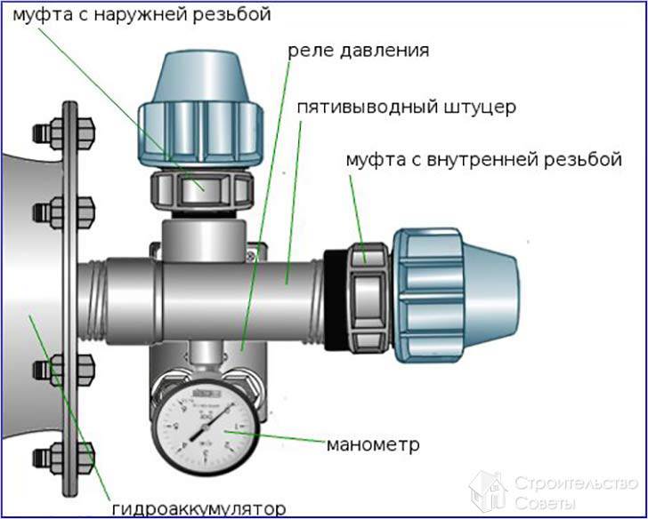
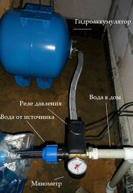
Before connecting the hydraulic accumulator for water supply, you need to check the air pressure in the tank. It should be less than the pump pressure when turned on, which is set on the relay, by a value of up to 1 bar. To connect the tank to the pump, you need to purchase a fitting with 5 outlets, a relay that regulates the pressure, a pressure gauge and sealant in the form of tow or FUM tape.
- One of important details When installing a hydraulic accumulator, there is a fitting with 5 outlets. Through this part, a pump, relay and pressure gauge are connected to the tank. Another 1 fitting outlet is intended for connecting a water supply system, which branches to water intake points. On initial stage the fitting is connected to the container through a rigid hose or directly through a flow flange with a valve. Then it is screwed to the separating part adjustable relay and a pressure gauge, as well as a pipe that is routed further from the pump.
- Particular attention must be paid to connecting the relay that controls pressure. The appliance has top cover which needs to be removed. Under it there will be 4 contacts with the inscriptions “network” and “pump”. Thanks to their presence, it is difficult to confuse the connection of wires. According to the marks, the wires connected from the pump and going to the network are connected.
Not all manufacturers put labels on relays, relying on the knowledge of the installer. If the person connecting the relay does not know which contact to connect this or that wire, it is better to contact a professional electrician.
All threaded connections must be carefully sealed. Tow or FUM tape are suitable for this work. Finally, you need to turn on the pump unit, after which you need to visually and by touch check the installation sites for leaks.
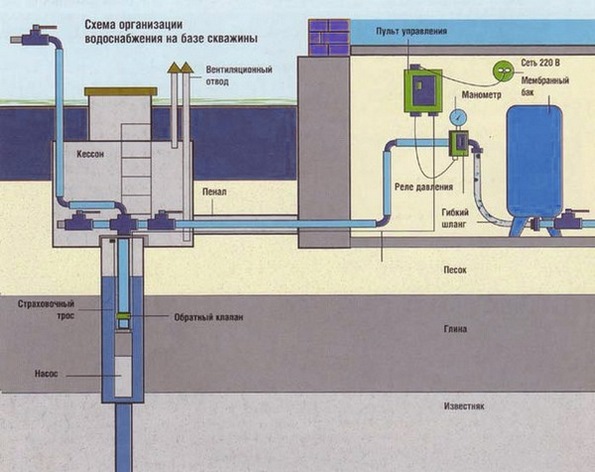
Connection diagram for the version with a submersible pump
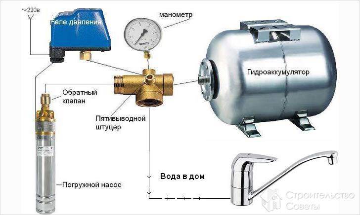
Already from the name you can understand that a submersible pump is placed in the aqueous environment of a well or well, from where water is supplied directly to the hydraulic accumulator. The water supply system with such a pump must be equipped with a check valve. This part prevents water from returning after the membrane to the deep water intake. Usually, check valve is mounted directly on the pump, while the other end is connected to the pressure pipeline. There are varieties of pumps in which the fitting on the cover has internal thread. Then during installation you need to use a part on which 2 external threads are cut. Following the check valve there is a pipe that is laid to the hydraulic accumulator.
When installing the pump, you need to take into account that the unit should not reach the bottom of the well or well by approximately 30 cm.
Video
The video provided clearly shows how the pump is connected to the accumulator.
A correctly selected hydraulic accumulator connection diagram for water supply systems will ensure ease of operation, as well as durability and cost-effectiveness of the system. The hydraulic accumulator is important node water supply system, which contains water and compressed air, separated by a membrane.
When the water flow parameters change (pressure decreases), the pump turns on and water is pumped into the accumulator, restoring the parameters of the required maximum pressure and then turns off. Further consumption water is coming from hydraulic device, preventing frequent switching on of the pumping unit, which occurs before next moment pressure drop to a minimum threshold. In addition, hydraulic accumulators can ensure the operation of the system for some time (depending on the volume of the tank) in the event of a power outage or damage to the pump.
IN general view All hydraulic accumulators consist of the following main parts:
- body with legs,
- membrane (in some models it is replaced by a rubber bulb located in the body according to the “vessel within a vessel” principle),
- air injection nipple, usually equipped with a protective cap.
Some products have distinctive design features:
- horizontal models are supplemented with a tap or valve for bleeding air,
- equipment for drinking water is supplied with “pears” made of special types of rubber, chemically neutral and not giving the liquid any foreign odors or tastes,
- hydraulic accumulators for heating systems are expansion tanks.
Based on the type of location, there are two types of models:
- Horizontal products are more often used for external pumps. In such cases, pumping units are installed on hydraulic accumulators.
- Vertical models are often equipped with water supply systems with submersible pumps.
The choice of configuration and installation of a hydraulic accumulator for water supply systems at the same time can be carried out based on the availability of free space for the installation of a particular model.
According to their purpose, the following types of hydraulic accumulators are distinguished:
- for cold water supply (the most popular option, used not only in houses with permanent residence, but also at dachas),
- for hot water supply, made from materials that can withstand high temperatures and installed during the installation of a complete system, including cold and hot water supply
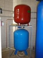
Heating accumulators are painted red, and equipment for water supply systems (hot water supply and hot water supply) are painted blue.
Connecting a hydraulic accumulator to a submersible pump
The connection diagram of the hydraulic accumulator to the submersible pump must be include check valve. Its presence will not allow compressed air to squeeze water back into the well through the membrane. The valve is mounted directly on the pump, before connecting other elements of the system.
 The photo shows a diagram of connecting a hydraulic accumulator to a submersible pump
 The first step is installation submersible pump. To do this, use a rope and a weight to determine the depth of the well, after which a place on the rope is marked to which the pumping unit will need to be lowered so that it is at a distance of 20-30 cm from the bottom. After fixing the pump, its pressure pipe or hose that goes to the surface is connected to the pressure switch using a manifold (fitting) with five connectors. A hydraulic accumulator and water supply system are connected in series to the same collector for supply to points of consumption. The remaining connector is used to connect the equipment control system.
Connecting a submersible pump to a hydraulic accumulator, like the other systems described below, necessarily requires sealing of all connections. For this purpose it is used FUM tape or tow with sealant.
Connection to surface pump
Before you begin connecting the hydraulic accumulator to the surface pump, you need to determine the required water supply parameters, in particular, decide what pressure is needed in the system. It is believed that water supply with a small number of consumption points can operate at a pressure of 1.5 atm. Depending on the availability of equipment that requires high pressure, this value can increase to 6 atm., more high pressure considered dangerous for communications and connecting elements.
Considering the selected pressure to be nominal, it is determined what reduction should be considered acceptable, that is, At what value will the pump turn on?. The critical value is set on the control relay, and from the nipple side the air pressure in the accumulator is measured when there is no water in it. The resulting value should be 0.5-1.0 atm below the minimum acceptable value.
 The connection diagram for the hydraulic accumulator to the surface pump is the same as for connecting pumping station, which already includes a hydraulic accumulator
 If no adjustment is required in this direction (for example, pumping), a hydraulic accumulator connection diagram for water supply systems is assembled
using a five-input collector. The hydraulic accumulator is installed first, then sequentially: pump pressure pipe, household water supply, pressure switch, pressure gauge.