Hello friends. Post topic - types and types circuit breakers(automatic, AB). I also want the results of the crossword puzzle tournament.
Types of machines:
Can be divided into AC switches, direct current and universal, working at any current.
Design - there are air, modular, in a molded case.
Rated current indicator. The minimum operating current of the modular machine is 0.5 Amperes, for example. Soon I will write about how to choose the right rated current for a circuit breaker, subscribe to blog news so as not to miss it.
Rated voltage, another difference. In most cases, ABs operate in networks with a voltage of 220 or 380 volts.
There are current-limiting and non-current-limiting.
All models of switches are classified according to the number of poles. They are divided into single-pole, two-pole, three-pole and four-pole machines.
Types of releases - overcurrent release, shunt release, undervoltage or zero voltage release.
The speed of operation of automatic switches. Allocate high-speed, normal and selective automata. There are with or without a time delay, independent or inversely dependent on the current, the operating time delay. Features can be combined.
They differ in terms of protection from environment– IP, mechanical impacts, material conductance. By type of drive - manual, motor, spring.
By the presence of free contacts and the method of connecting conductors.
Machine types:
What does type AB mean?
Circuit breakers contain two types of circuit breakers - thermal and magnetic.
The magnetic quick release is designed for short circuit protection. The tripping of the circuit breaker can take place from 0.005 to several seconds.
The thermal circuit breaker is much slower, designed for overload protection. Works with the help of a bimetallic plate that heats up when the circuit is overloaded. Response time from a few seconds to minutes.
The combined tripping characteristic depends on the type of connected load.

There are several types of AV shutdown. They are also called - types of time-current characteristics of the trip.
A, B, C, D, K, Z.
A- used to open circuits with a large long electrical wiring, serves as a good protection for semiconductor devices. They work at 2-3 rated currents.
B– for the lighting network general purpose. They operate at 3-5 rated currents.
C– lighting circuits, electrical installations with moderate starting currents. It can be motors, transformers. The overload capacity of the magnetic circuit breaker is higher than that of type B circuit breakers. They operate at 5-10 rated currents.
D- used in circuits with active-inductive load. For motors with high starting currents, e.g. At 10-20 rated currents.
K– inductive loads.
Z– for electronic devices.
It is better to look at the data on the operation of switches of types K, Z in the tables specifically for each manufacturer.
It seems everything, if there is something to add, leave a comment.
Production automation- this is a process in the development of machine production, in which the functions of control and control, previously performed by a person, are transferred to instruments and automatic devices. The introduction of automation in production can significantly increase labor productivity and product quality, reduce the proportion of workers employed in various areas of production.
Before the introduction of automation tools, the replacement of physical labor took place through the mechanization of the main and auxiliary operations of the production process. Intellectual labor for a long time remained non-mechanized (manual). Currently, operations of physical and intellectual labor, amenable to formalization, are becoming the object of mechanization and automation.
Modern production systems that provide flexibility in automated production include:
CNC machines first appeared on the market in 1955. Mass distribution began only with the use of microprocessors.
· Industrial robots first appeared in 1962. Mass distribution is associated with the development of microelectronics.
· Robotized technological complex (RTC), first appeared on the market in 1970-80s. Mass distribution began with the use of programmable control systems.
· Flexible production systems, characterized by a combination of technological units and computer-controlled robots, with equipment for moving workpieces and changing tools.
Automated warehouse systems Automated Storage and Retrieval Systems, AS/RS). Provide for the use of computer-controlled lifting and transport devices that lay products in the warehouse and remove them from there on command.
computer-based quality control systems Computer-aided Quality Control, CAQ) - a technical application of computers and computer-controlled machines for checking the quality of products.
· Computer-aided design system Computer-aided Design, CAD) is used by designers in the development of new products and technical and economic documentation.
· Planning and coordination individual elements plan using a computer Computer-aided Planning, CAP). SAR- is divided according to various characteristics and purposes, according to the state of approximately the same elements.
COMPUTER (electronic computer)
Outline the main provisions of the technology of cleaning and washing operations. Compare cleaning and washing equipment and justify its choice. Evaluate the possibilities of designing a cleaning and washing station.
Washing work is often carried out manually using a hose with a gun and a pump of low (0.3-0.4 MPa) or high (1.5-2.0 MPa) pressure or mechanized using washing installations. A progressive way is the mechanized and automatic washing of cars, car components and parts, which allows you to replace as much as possible manual labor and increase labor productivity with high-quality washing.
So let's take a look at the main existing species car washes:
A hand wash is a traditional car wash performed by humans. The car is washed with water and car shampoo using sponges, brushes, rags, etc., that is, contact washing.
The advantage of a manual car wash is that a person in the process of work sees which areas are more polluted and need more thorough cleaning.
Cons: with such a wash, there is a high risk of damaging the paintwork on the car body; and a manual car wash will take the largest number time.
A brush car wash is a contact wash in which people do not participate, it is carried out with the help of special automatic installations. The process consists of several stages: first, the machine is washed with water under pressure, then with hot foam, then quickly rotating brushes are taken to clean the machine of dirt. The last step is to apply protective wax and dry the car.
A brush washer is suitable for tough dirt that a touchless washer might not be able to handle. Brushes are made of synthetic threads, rounded at the ends. High-quality brushes should not scratch the paintwork.
Touchless car wash is a wash with active foams. This technology is used in conventional contactless car washes where washing is carried out by people using special devices, as well as in conveyor and portal car washes. In the process of such washing, the main layer of dirt is washed off with a jet of water under high pressure, then active foam is applied with special equipment, under the influence of which the remaining dirt lags behind the body, and after a while the foam is also washed off with a stream of water under pressure. As a rule, such a wash ends with the application of a protective polish, which will give an attractive shine and protect against rapid pollution and the harmful effects of the environment.
A touchless car wash or pressure washer causes the least damage to the body paintwork.
Dry washing is washing with a special shampoo-polish. Motorists carry out such a wash with their own hands. This wash does not require water. Manufacturers of dry shampoo shampoos claim that the silicone oil and surfactants in the shampoo soften, soak and coat dirt particles, ensuring the integrity of the paintwork in this type of washing. Dry washing for a while will provide shine and protection of the body from the effects of negative environmental factors.
The disadvantage of such a wash is the impossibility or inconvenience of processing hard-to-reach places car. Therefore, this type of washing is recommended to be used in between water washes to keep the car clean and tidy.
There are two types of automatic car washes:
Conveyor type (or tunnel). This is when the vehicle is slowly conveyed through several arches with various cleaning and rinsing functions (for example: pre-wash, wheel wash, underbody wash, high pressure wash, dryer).
The biggest plus of such car washes is the speed of work and great performance. All arches work simultaneously, so the driver does not have to wait for the previous car to go through all the procedures.
portal type. With such a wash, the car is stationary, and the portal (washing arch) moves relative to it.
The disadvantage compared to the conveyor car wash is that the portal car wash is not able to quickly take such a number of cars.
Outline the main provisions of the technology of diagnostic work. Compare diagnostic equipment and justify its choice. Evaluate the possibilities of designing a post of diagnostic work
1.1. The Guide sets out the main provisions for organizing the diagnostics of the technical condition of the rolling stock road transport in cars, trucks, buses and mixed motor transport enterprises (ATP) of various capacities.
1.2. Technical diagnostics is part of technological process maintenance (TO) and repair (R) of cars, the main method of carrying out control and control and adjustment work. In control system technical service ATP diagnostics is a subsystem of information.
1.3. The organization of vehicle diagnostics is based on the planned preventive maintenance and repair system operating in the USSR, set forth in the "Regulations on the maintenance and repair of rolling stock of road transport."
1.4. In the conditions of ATP, technical diagnostics should solve the following tasks:
Refinement of failures and malfunctions identified during operation;
Identification of cars, the technical condition of which does not meet the requirements of traffic safety and environmental protection;
Identification of malfunctions before maintenance, the elimination of which requires labor-intensive repair or adjustment work in the current repair zone (TR);
Clarification of the nature and causes of failures or malfunctions identified in the process of maintenance and repair;
Forecasting the failure-free operation of units, systems and the car as a whole within the inter-inspection run;
Issuance of information on the technical condition of the rolling stock for planning, preparation and management of the production of maintenance and repair;
Quality control of the performed maintenance and repair works.
Vehicle diagnostic technology contains: list and sequence of operations, repeatability coefficients, labor intensity, category of work, tools and equipment used, specifications for the performance of work.
3.2. Depending on the shift program and the type of rolling stock, diagnostic work is carried out at separate posts (dead-end or through) or posts located in a line.
3.3. The technology is compiled separately for the types of diagnostics D-1, D-2 and others.
3.4. For specialized repair and adjustment and diagnostic posts, Dr technology is compiled for individual diagnosed units, systems and types of work ( brake system, steering, wheel alignment, wheel balancing, headlight setting, etc.).
3.5. When developing a diagnostic technology, one should be guided by the established lists of diagnostic operations by types of diagnostics (Appendices 1, 2), which are part of the control work given in the current Regulations on the maintenance and repair of rolling stock of road transport, as well as a list of diagnostic features (parameters) and their limit values (Appendix 5).
3.6. Typical diagnostic technology should contain preparatory work performed before diagnosing, the actual diagnosing, adjustment and final work performed based on the results of diagnosing.
3.7. The diagnostic technology D-1 and D-2 is compiled taking into account the specific conditions of the ATP.
3.8. Diagnostics at the posts (lines) in the scope of D-1 and D-2 are performed by diagnostic operators or diagnostic mechanics. Drivers are attached to help them, who, in addition to driving cars in the process of diagnosing, are engaged in placing cars at diagnostic posts, removing them, distilling to the appropriate zone (storage, waiting, MOT and TR), as well as preparatory and some adjustment work . In the ATP, where there are no full-time ferry drivers, this work is assigned to the drivers of the vehicles being diagnosed or column mechanics who have the right to drive.
Control and diagnostic (Dr) and adjustment operations at the posts of maintenance and repair are carried out by repair workers.
3.9. At posts (lines) D-1 and D-2 repair work related to the elimination of identified faults, as a rule, are not performed. The exception is adjustment work, the implementation of which is provided for by the technological process in the process of diagnosing.
3.10. Performing diagnostic operations before maintenance and routine maintenance is mandatory, regardless of the availability of diagnostic tools. In the absence of the latter in the ATP, the control and diagnostic operations provided for by this "Manual ..." are performed subjectively by a diagnostician in order to identify the required volumes current repairs performed before maintenance.
The main difference between these switching devices from all others similar devices consists of a complex combination of abilities:
1. maintain nominal loads in the system for a long time due to the reliable transmission of powerful electricity flows through their contacts;
2. protect operating equipment from accidental malfunctions in wiring diagram due to the rapid removal of power from it.
Under normal operating conditions of the equipment, the operator can manually switch the loads with circuit breakers, providing:
different power schemes;
changing the network configuration;
decommissioning equipment.
Emergencies in electrical systems ah arise instantly and spontaneously. A person is not able to quickly respond to their appearance and take measures to eliminate them. This function is assigned to automatic devices built into the switch.
In the energy sector, the division of electrical systems by types of current is accepted:
constant;
alternating sinusoidal.
In addition, there is a classification of equipment according to the magnitude of the voltage on:
low voltage - less than a thousand volts;
high voltage - everything else.
For all types of these systems, their own circuit breakers are created, designed for repeated operation.

AC circuits
According to the power of the transmitted electricity, circuit breakers in AC circuits are conventionally divided into:
1. modular;
2. molded case;
3. power air.
Modular designs
Specific execution in the form of small standard modules with a width multiple of 17.5 mm determines their name and design with the possibility of mounting on a DIN rail.
The internal structure of one of these circuit breakers is shown in the picture. Its body is completely made of durable dielectric material, excluding .

The supply and outgoing wires are connected to the upper and lower terminal clamp, respectively. For manual control The state of the switch is set to a lever with two fixed positions:
the upper one is designed to supply current through a closed power contact;
lower - provides a break in the power circuit.
Each of these machines is designed for long work at a certain value (In). If the load becomes greater, then the power contact breaks. For this, two types of protection are placed inside the case:
1. thermal release;
2. current cutoff.
The principle of their operation makes it possible to explain the time-current characteristic, which expresses the dependence of the protection response time on the load or accident current passing through it.
The graph shown in the picture is for one specific circuit breaker, when the cut-off operating zone is selected to be 5÷10 times the rated current.

During the initial overload, a thermal release operates, made of which, with increased current, gradually heats up, bends and acts on the tripping mechanism not immediately, but with a certain time delay.
In this way, it allows small overloads associated with short-term connection of consumers to self-eliminate and eliminate unnecessary disconnections. If the load provides critical heating of the wiring and insulation, then the power contact breaks.
When an emergency current arises in the protected circuit, capable of burning the equipment with its energy, then the electromagnetic coil comes into operation. It impulse due to the surge of the load that has arisen throws the core onto the tripping mechanism in order to instantly stop the transcendental mode.
The graph shows that the higher the short-circuit currents, the faster they are turned off by the electromagnetic release.
According to the same principles, a household automatic steam fuse works.
When large currents are interrupted, a electric arc, the energy of which can burn out the contacts. To exclude its action in circuit breakers, an arc chute is used, which divides the arc discharge into small flows and extinguishes them due to cooling.
Multiplicity of cut-offs of modular structures
Electromagnetic releases are configured and selected to work with certain loads because they create different transients at start-up. For example, during the switching on of various lamps, a short-term inrush current due to the changing resistance of the filament can approach three times the nominal value.
Therefore, for the outlet group of apartments and lighting circuits, it is customary to choose circuit breakers with a time-current characteristic of type "B". It is 3÷5 In.
Asynchronous motors cause higher overload currents when spinning the driven rotor. For them, automatic machines with the characteristic “C” are selected, or - 5 ÷ 10 In. Due to the created time and current margin, they allow the motor to spin up and guarantee to reach the operating mode without unnecessary shutdowns.
IN industrial productions on machines and mechanisms there are loaded drives connected to engines that create more increased overloads. For such purposes, circuit breakers of characteristic "D" with a rating of 10 ÷ 20 In are used. They have proven themselves well when working in circuits with active-inductive loads.
In addition, automata have three more types of standard time-current characteristics that are used for special purposes:
1. "A" - for long wiring with an active load or protection of semiconductor devices with a value of 2 ÷ 3 In;
2. "K" - for pronounced inductive loads;
3. "Z" - for electronic devices.
In the technical documentation for different manufacturers, the cutoff actuation ratio for the last two types may differ slightly.
This class of devices is capable of switching higher currents than modular designs. Their load can reach up to 3.2 kiloamperes.

They are manufactured according to the same principles as modular structures, but, taking into account the increased requirements for the transmission of increased loads, they are trying to give them relatively small dimensions and high technical quality.
These machines are designed for safe work on industrial facilities. By the value of the rated current, they are conditionally divided into three groups with the possibility of switching loads up to 250, 1000 and 3200 amperes.
The design of their housing: three- or four-pole models.
Power air circuit breakers
They work in industrial plants and operate with currents of very large loads up to 6.3 kiloamperes.

These are the most complex devices of switching devices of low-voltage equipment. They are used for the operation and protection of electrical systems as incoming and outgoing devices of high-power switchgear and for connecting generators, transformers, capacitors or large electric motors.
Schematic representation of them internal device shown in the picture.

Here, a double break of the power contact is already used and arc chute chambers with gratings are installed on each side of the disconnection.
The switching coil, the closing spring, the motor drive for charging the spring and the automation elements are involved in the operation algorithm. To control the flowing loads, a current transformer with a protective and measuring winding is built in.
Circuit breakers of high-voltage equipment are very complex technical devices and are made strictly individually for each voltage class. They are usually used.
They are required to:
high reliability;
security;
speed;
ease of use;
relative noiselessness during operation;
optimal cost.
Loads that break during emergency shutdown are accompanied by a very strong arc. To extinguish it, various ways, including breaking the circuit in a special environment.
This switch includes:
contact system;
arc extinguishing device;
live parts;
insulated body;
drive mechanism.
One of these switching devices is shown in the photograph.

For high-quality operation of the circuit in such designs, in addition to the operating voltage, take into account:
the nominal value of the load current for its reliable transmission in the on state;
the maximum short-circuit current in terms of the effective value that the tripping mechanism can withstand;
permissible component of the aperiodic current at the moment of circuit break;
the possibility of automatic reclosing and the provision of two AR cycles.
According to the methods of extinguishing the arc during shutdown, the circuit breakers are classified into:
oil;
vacuum;
air;
SF6;
autogas;
electromagnetic;
autopneumatic.
For reliable and convenient operation they are equipped with a drive mechanism that can use one or more types of energy or combinations thereof:
cocked spring;
lifted load;
compressed air pressure;
electromagnetic pulse from the solenoid.
Depending on the conditions of use, they can be designed to operate under voltage from one to 750 kilovolts inclusive. Naturally they have different design. dimensions, possibilities of automatic and remote control, protection settings for safe operation.
Auxiliary systems of such circuit breakers can have a very complex branched structure and be placed on additional panels in special technical buildings.
DC circuits
These networks also have a huge number of circuit breakers with different capabilities.
Electrical equipment up to 1000 volts
Here, modern modular devices that can be mounted on a Din-rail are being massively introduced.
They successfully complement the classes of old automata such as , AE and other similar ones, which were fixed on the walls of the shields with screw connections.
Modular DC designs have the same design and principle of operation as their counterparts on AC voltage. They can be performed by one or several blocks and are selected according to the load.
Electrical equipment above 1000 volts
High-voltage circuit breakers for direct current operate at electrolysis plants, metallurgical industrial facilities, railway and urban electrified transport, and energy enterprises.

Main technical requirements to the operation of such devices correspond to their counterparts on alternating current.
hybrid switch
Scientists from the Swedish-Swiss company ABB managed to develop a high-voltage DC switch that combines two power structures in its device:
1. SF6;
2. vacuum.
It is called hybrid (HVDC) and uses the technology of sequential arc extinguishing in two environments at once: sulfur hexafluoride and vacuum. For this, the following device is assembled.
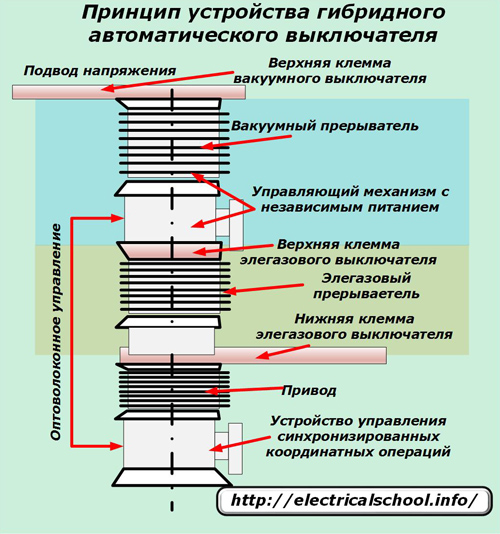
Voltage is applied to the top busbar of the hybrid vacuum circuit breaker, and the voltage is removed from the bottom busbar of the SF6 circuit breaker.
The power parts of both switching devices are connected in series and controlled by their individual drives. In order for them to work simultaneously, a synchronized coordinate operations control device was created, which transmits commands to a control mechanism with independent power supply via a fiber optic channel.
Through the use of high-precision technologies, the design developers managed to achieve consistency in the actions of the actuators of both drives, which fits into a time interval of less than one microsecond.
The circuit breaker is controlled by a relay protection unit built into the power line through a repeater.
The hybrid circuit breaker made it possible to significantly increase the efficiency of composite SF6 and vacuum structures by using their combined characteristics. At the same time, it was possible to realize advantages over other analogues:
1. the ability to reliably turn off short-circuit currents at high voltage;
2. the possibility of a small effort for switching power elements, which made it possible to significantly reduce the dimensions and. respectively, the cost of equipment;
3. the availability of various standards for the creation of structures operating as part of a separate circuit breaker or compact devices at one substation;
4. ability to eliminate the consequences of a rapidly increasing restoring voltage;
5. the possibility of forming a basic module for working with voltages up to 145 kilovolts and above.
A distinctive feature of the design is the ability to break the electrical circuit in 5 milliseconds, which is almost impossible to perform with power devices of other designs.
The hybrid circuit breaker device was named one of the top ten designs of the year by the MIT (Massachusetts Institute of Technology) Technology Survey.
Other manufacturers of electrical equipment are also engaged in similar studies. They also achieved certain results. But ABB is ahead of them in this matter. Its management believes that large losses occur during the transmission of AC electricity. They can be significantly reduced by using high-voltage DC circuits.
What is a circuit breaker?
Circuit breaker(automatic) is a switching device designed to protect the electrical network from overcurrents, i.e. against short circuits and overloads.
The term "switching" means that this unit can turn on and off electrical circuits, in other words, switch them.
Circuit breakers come with an electromagnetic release that protects the electrical circuit from short circuits and a combined release - when, in addition to the electromagnetic release, a thermal release is used to protect the circuit from overload.
Note: In accordance with the requirements of the PUE, household electrical networks must be protected from both short circuits and overload, therefore, to protect home electrical wiring it is necessary to use automatic machines with a combined release.
Circuit breakers are divided into single-pole (used in single-phase networks), two-pole (used in single-phase and two-phase networks) and three-pole (used in three-phase networks), there are also four-pole circuit breakers (can be used in three-phase networks with a TN-S grounding system).
The device and principle of operation of the circuit breaker.
The figure below shows circuit breaker device with combined release, i.e. having both electromagnetic and thermal release.

1.2 - respectively, the lower and upper screw terminals for connecting the wire
3 - moving contact; 4 - arc chute; 5 - flexible conductor (used to connect the moving parts of the circuit breaker); 6 - electromagnetic release coil; 7 - the core of the electromagnetic release; 8 - thermal release (bimetallic plate); 9 - release mechanism; 10 - control handle; 11 - latch (for mounting the machine on a DIN rail).
The blue arrows in the figure show the direction of current flow through the circuit breaker.
The main elements of the circuit breaker are electromagnetic and thermal releases:
Electromagnetic release provides protection electrical circuit from short circuit currents. It is a coil (6) with a core (7) located in its center, which is mounted on a special spring, the current in normal operation passing through the coil according to the law of electromagnetic induction creates an electromagnetic field that attracts the core inside the coil, however, the forces of this electromagnetic field do not enough to overcome the resistance of the spring on which the core is installed.
In the event of a short circuit, the current in the electrical circuit instantly increases to a value several times greater than the rated current of the circuit breaker, this short circuit current passing through the coil of the electromagnetic release increases the electromagnetic field acting on the core to such a value that its pulling force is enough to overcome the resistance springs, moving inside the coil, the core opens the movable contact of the circuit breaker, de-energizing the circuit:

In the event of a short circuit (i.e., with an instantaneous increase in current by several times), the electromagnetic release switches off the electrical circuit in a fraction of a second.
Thermal release provides protection of the electrical circuit against overload currents. An overload can occur when electrical equipment is connected to the network with a total power exceeding the allowable load of this network, which in turn can lead to overheating of the wires, destruction of the insulation of the electrical wiring and its failure.
The thermal release is a bimetallic plate (8). Bimetallic plate - this plate is soldered from two plates of different metals (metal "A" and metal "B" in the figure below) with different coefficients of expansion when heated.

When a current exceeding the rated current of the circuit breaker passes through the bimetallic plate, the plate begins to heat up, while the metal "B" has a higher coefficient of expansion when heated, i.e. when heated, it expands faster than metal "A", which leads to the curvature of the bimetallic plate, bending it acts on the release mechanism (9), which opens the moving contact (3).

The operating time of the thermal release depends on the magnitude of the excess current of the power supply network of the rated current of the machine, the greater this excess, the faster the release will operate.
As a rule, the thermal release trips at currents 1.13-1.45 times the rated current of the circuit breaker, while at a current 1.45 times the rated current, the thermal release will turn off the machine after 45 minutes - 1 hour.
The operating time of circuit breakers is determined by their
With any disconnection of the circuit breaker under load, an electric arc is formed on the moving contact (3), which has a destructive effect on the contact itself, and the higher the disconnected current, the more powerful the electric arc and the greater its destructive air. action. In order to minimize damage from the electric arc in the circuit breaker, it is directed to the arc chute (4), which consists of separate, parallel installed plates, falling between these plates, the electric arc is crushed and damped.
3. Marking and characteristics of automatic switches.

VA47-29— type and series of circuit breaker
Rated current- the maximum current of the electrical network at which the circuit breaker is able to operate for a long time without emergency shutdown of the circuit.
Standard values of rated currents of circuit breakers: 1; 2; 3; 4; 5; 6; 8; 10; 13; 16; 20; 25; 32; 35; 40; 50; 63; 80; 100; 125; 160; 250; 400; 630; 1000; 1600; 2500; 4000; 6300, Amp.
Rated voltage- the maximum mains voltage for which the circuit breaker is designed.
PCS- ultimate breaking capacity of the circuit breaker. This figure shows the maximum short circuit current that is able to turn off this circuit breaker while maintaining its performance.
In our case, the PKS is indicated as 4500 A (Amps), which means that with a short circuit current (short circuit) less than or equal to 4500 A, the circuit breaker is able to open the electrical circuit and remain in good condition, if the short circuit current exceeds this figure, it becomes possible to melt the moving contacts of the machine and weld them to each other.
Tripping characteristic- determines the operating range of the electromagnetic release of the circuit breaker.
For example, in our case, an automatic machine with a characteristic “C” is presented, its response range is from 5 I n to 10 I n inclusive. (I n - rated current of the machine), i.e. from 5 * 32 \u003d 160A to 10 * 32 + 320, this means that our machine will provide instant circuit shutdown already at currents of 160 - 320 A.

Note:
- The standard response characteristics (provided by GOST R 50345-2010) are characteristics "B", "C" and "D";
- The scope is indicated in the table according to established practice, however, it may be different depending on the individual parameters of specific electrical networks.
4. Circuit breaker selection
Note: Read the full methodology for calculating and selecting circuit breakers in the article: "
The development of power grid security tools has become relevant since their inception. Various overloads led not only to cable damage, but also to fires.
To date, the most popular devices of this type are circuit breakers.
They help prevent events such as fires, damage to electrical wiring. Since they are automatic, the operation occurs without human intervention. Choosing the right switch will help protect the room from accidents.
Design and principle of operation
Understanding the circuit breaker's automatic tripping mechanism will help you select the right model. Structurally, the machine includes the following key elements:
- terminals;
- toggle switch;
- electromagnetic release;
- bimetallic plate.
 Depending on the type of overload, one of two mechanisms is triggered.
When an overload of the circuit occurs with a current that exceeds the nominal value by several times, the bimetallic plate is triggered. It heats up within a few seconds, resulting in its thermal expansion. When a certain size is reached, its significant bending is carried out and the chain opens. The setting of the plate parameters is carried out by the manufacturer. For switches used in everyday life, the operating time takes 5–20 s. They are usually marked with the letters: B, C, D.
The short circuit mode (short circuit) is characterized by an avalanche-like increase in current, exceeding not only the nominal value, but also its maximum permissible loads. There is no time left to heat the plate during the jump, otherwise the wiring may melt. In such a situation, an electromagnetic release is triggered. The magnetic field drives the core, which opens the circuit. Instant operation allows you to protect the premises from the consequences of a short circuit.
Classification
Electric machines differ in the following key characteristics:
- number of poles;
- time current characteristic;
- operating current;
- breaking capacity.
Number of poles
 This characteristic corresponds to the number of electrical wiring lines that can be directly connected to the machine. All output wires will be disconnected at the same time when the machine is triggered.
Single pole machine. This is the simplest type of circuit protection device. Only 2 wires are connected to it: one goes to the load, the second is power. It mounts on a standard 18mm din rail. The power wire is brought in from above, and the load to the bottom terminal. It can work in single, two or three phase power lines. In addition to the power and load wires, it has a neutral and ground, which are connected to the corresponding busbars. Such machines are not installed at the input, since the circuit will open only along the phase line. The zero wiring remains closed and, in case of failures, potential may remain on it.
A two-pole machine, its difference from a single-pole one. This type of circuit breakers allows you to completely de-energize the electrical wiring of the room. It allows you to synchronize the moment of turning off two of its output lines. The latter leads to more high level safety during electrical work. It can be used as a separate toggle switch for appliances such as a water heater or washing machine. The connection is made using 4 cables: a pair at the input and output.
A simple question is logical: is it possible to connect two single-pole machines instead of one two-pole one? Of course no. After all, when the shutdown is automatically triggered, all output lines are turned off at the two-terminal network. For a pair of independent automata, overload may not occur on one of the lines and the de-energization will be partial. In ordinary apartments, you can connect a phase and neutral line to this machine. When opened, a complete deenergization of the entire group of devices that are powered from it will occur.
 Three and four-pole machines. All three or four phase conductors are connected to the poles of the corresponding circuit breaker. They are used when connected by a star, when the phase wires are protected from overloads, and the middle wire remains switched all the time, or by a triangle, when there is no middle central cable, and the phase wires are protected.
If an overload occurs on one of the lines, a shutdown occurs immediately on all the others. 6 (three-phase machine) or 8 wires are connected to these machines. 3-4 at the output and the same number of lines at the output. They are mounted on din rails with a length of 54 (three-phase machine) and 72 mm, respectively. They are used most often in industrial installations, when connecting powerful electric motors.
Time current parameter
The nature of food consumption various devices varies even when power values match. Uneven dynamics of consumption during correct operation, a surge in load during turn-on - all these phenomena lead to significant changes in such a parameter as current consumption. Power dissipation can lead to false positive switch.
To exclude such situations, dynamic operation parameters are introduced, called time-current characteristics of circuit breakers. Automata according to this parameter are divided into several types. Each group has its own response time. The front panel of the switch is marked with the corresponding letter from the list: A, B, C, D, K, Z.

Rated current
The differences of automata depending on the nominal values of the current are divided into several groups (12 current levels). It is directly related to the response time when the power consumption is exceeded. The operating value can be determined purely theoretically by adding up the sums of the currents consumed by each of the devices separately. In this case, a small margin should be taken. Also, do not forget about the possibilities of electrical wiring.
Machines are designed primarily to prevent damage to it. Depending on the metal of the wires and their cross section, the maximum load is calculated. The ratings of the circuit breakers for current allow such a separation.

Breaking capacity
This parameter depends on the maximum current in the event of a short circuit, provided that the machine will disconnect the network. According to the magnitude of the short-circuit current, all automata are divided into three groups.
- The first includes devices with a nominal value of 4.5 kA. They are used in private houses intended for human habitation. The current limit is approximately 5 kA. This is due to the fact that the resistance of the system of conductive cables leading to the house from the substation is 0.05 ohms.
- The second group has rated 6 kA. This level is already used in residential apartment buildings And in public places. The current limit can reach 5.5 kA (wiring resistance 0.04 Ohm). In this case, models of types are used: B, C, D.
- In industrial plants the nominal value is 10 kA. The limit value of the current that can occur in the circuit near the substation has the same value.
How to choose the right machine
 Until recently, porcelain fuses with fusible elements were widely used. They were well suited for the same type of load of Soviet apartments. Now the number of household appliances has become much larger, as a result of which the probability of getting a fire with old fuses has increased. To prevent this, it is necessary to carefully approach the choice of a machine with the correct characteristics. Excess power reserves should be avoided. The final choice is made after a few simple steps.
Determining the number of poles
When determining given parameter switch should be guided simple rule. If you plan to secure sections of the circuit with devices that have low power consumption (for example, lighting devices), then it is better to leave your choice on a single-pole machine (usually class B or C). If you plan to connect a complex household device with significant power consumption (washing machine, refrigerator), then you should install a two-pole machine (class C, D). If a small production workshop or a garage with multi-phase propulsion systems is being equipped, then it is worth choosing a three-pole option (class D).
Power consumption calculation
As a rule, by the time it is planned to connect the machine, the wiring to the room has already been connected. Based on the cross section of the cores and the type of metal (copper or aluminum), it is possible to determine maximum power. For example, for a copper core of 2.5 mm 2, this value is 4–4.5 kW. But the wiring is often summed up with a large margin. Yes, and the calculation should be done before the start of all installation work.
 In this case, you will need a value about what the total power will be used by all devices. It is always possible to turn them on at the same time. So, in an ordinary kitchen, the following appliances are often used:
- fridge- 500 W;
- Electric kettle- 1700 W;
- microwave– 1800 W
The total load is 4 kW and a 25 A machine is enough for it. But there are always consumers who turn on sporadically and can create factors that contribute to the operation of the switch. Such devices can be a combine or a mixer. Therefore, you should take the machine with a margin of 500-1200 watts.
Rated current calculation
Since the power in single-phase networks is equal to the product of voltage and current, it is easy to determine the current as a quotient of power and voltage. For the above example, this value is easy to calculate, knowing that the mains voltage is 220 V. The current consumption is 18.8 A. With a margin of 500-1200 V, it will be 20.4-23.6 A.
In order for the work not to stop even with such short-term excesses of the load, the rated current for the machine can be taken equal to 25 A. Approximately the same value corresponds to the rating, based on a copper cable with a cross section of 2.5 mm 2, which is enough with a margin for such loads. A machine with a rated current of 25 A will work before it starts to heat up.
Determination of the current characteristic time
 This parameter is determined by a special table that lists the starting currents and their flow time. For example, for a household refrigerator, the starting current ratio is 5. With a power of 500 W, the operating current is 2.2 A. The starting current will be 2.2 * 7 \u003d 15.4 A. Data on the frequency is also taken from a special table.
Table No. 1. Starting currents and pulse durations for household appliances
For the selected device, this characteristic does not exceed 3 s. The choice becomes obvious: for such a consumer, it is necessary to take a type B circuit breaker. It is permissible to make a choice of the machine according to the load power. Can be skipped final stage, having opted for a class B switch. For domestic needs, the characteristics are most often sufficient electrical switches class B and C.


