To release gas after the regulator in the event of a short-term increase in gas pressure above the set value, safety relief valves (PSV) must be used. PSK is a valve closed in operational condition; it opens for a short period of time, and after reaching the pressure at the controlled point of the nominal value, it automatically closes.
PSK can be spring and membrane. Spring PSC must be equipped with a device for their forced opening and control blowing in order to prevent sticking, freezing and sticking of the spool to the seat, as well as to remove solid particles trapped between the sealing surfaces.
PSK are divided into full-lift and low-lift. For low-lift valves (such as PSK), the shutter opens gradually, in proportion to the increase in pressure at the controlled point of the gas pipeline. Full-lift valves (SPKR4R-16) open completely and sharply, with a jerk, and just as sharply, with a spool hitting the seat, they close when the pressure drops. That is, the full-lift valve has a two-position position: "closed" and "open".
When the maximum allowable setting pressure is reached, the PSK valve must open without fail until it is fully lifted, and operate stably in the open position. The valve must close when the pressure drops to the nominal value or below it by 5% and ensure tightness. In the event of a delay in closing the gate, the gas pressure in the network may drop significantly, which may lead to disruption of the system operation, as well as release into the atmosphere of relatively a large number gas.
For low-lift PSK when closing the shutter after reset required amount gas, it is difficult to achieve tightness of the shutter, since for this it may be necessary to apply more force than in the “closed” mode.
Such PSK stop gas discharge only after the pressure is reduced to 0.8-0.85% of the operating pressure, which leads to a constant or long-term discharge of gas into the atmosphere. The main advantage of membrane PSCs is the presence of an elastic membrane in their design, which acts as a sensitive element. If in spring valves the spool performs the functions of both a sensitive element and a shut-off body, then in diaphragm valves the spool performs only shut-off functions. The membrane makes it possible to increase the sensitivity of the PSC as a whole and to expand the area of their use, including low gas pressure. PSK should provide opening when the established working pressure is exceeded by no more than 15%.
The choice of PSK design should be made in accordance with the throughput.
The amount of gas to be discharged by the PSK should be determined:
- if there is a slam-shut valve in front of the pressure regulator according to the formula Q≥0.0005Q d, where Q is the amount of gas to be discharged by the PSC within an hour at t = 0 ° C and P bar = 0.10132 MPa, m 3 / h; Q d - design capacity of the pressure regulator at t = 0 ° C and P bar = 0.10132 MPa, m 3 / h;
- in the absence of a shut-off valve in front of the pressure regulator according to the formulas: for pressure regulators with a saddle valve - Q≥0.01Q d , for control dampers - Q≥0.02Q d .
Low-lift membrane and spring PSK have a small throughput. Thus, the capacity of SPPK4R-50-16 (seat diameter 30 mm) at an operating pressure of 0.125 MPa is 830 m3/h, and PSK-50S/125 (seat diameter 50 mm) is only 10 m3/h. This is due to the low lift height of the spool. The throughput capacity of PSK-50 (KPS-50) valves with guide ribs at low pressure is: 0.5-3 m3/h, at medium pressure - 7-20 m3/h (at a pressure in the inlet pipe PSK 1.15 of the setting pressure) .
The capacity of the PSK-50 without guide ribs can be taken twice as large with the same parameters.
The table (p. 1245) shows the main specifications serially produced PSK. In addition to these PSKs, relief valves can also be a part (component element) of combined gas pressure regulators.
Description
To limit the gas pressure indicator using the method of dumping it into the atmosphere in cases where the permissible value is exceeded, PSK-50 relief devices are used. Products are installed at stations, gas pipelines, characterized by different pressure indicators. Operating conditions refer to UHL 2GOST 15150-69, i.e. optimal performance provided at a temperature of -40°C to +60°C.
These valves do not negative impact to the atmosphere and environment. The service life is at least 15 years. The design is a body, covers with a seal, a screw, plates, springs, membranes. When the pressure changes, the valve opens, allowing the gas to escape. After the process is completed, the valve returns to the closed state.
We also offer you to buy a repair pipe clamp at a bargain price.
Specifications
safety relief valve
| Parameter or dimension name | Value |
|---|---|
| 1 Nominal diameter, mm | 50 |
| 2 Maximum valve opening pressure, kPa (kgf / cm 2) | |
| PSK-50N/5 | 5(0,05) |
| PSK-50S/20 | 20(0,2) |
| PSK-50S/50 | 50(0,5) |
| PSK-50S/125 | 125(1,25) |
| PSK-50V/400 | 400 (4) |
| PSK-50V/700 | 700 (7) |
| 3 Operation setting range, kPa | |
| PSK-50N/5 | 2 to 5 |
| PSK-50S/20 | from 5 to 20 |
| PSK-50S/50 | from 20 to 50 |
| PSK-50S/125 | from 50 to 125 |
| PSK-50V/400 | from 125 to 400 |
| PSK-50V/700 | from 400 to 700 |
| 4 Seal tightness class | B according to GOST 9544-2005 |
| 5 Connecting dimensions: at the inlet and at the outlet there is an internal pipe thread according to GOST 6357-81, inches | 2 |
| 6 dimensions, mm, no more | |
| - diameter | 220 |
| - height | 255 |
| 7 Weight, kg, no more | 5,0 |
Note: The safety relief valve must be set to 1.15 working pressure.
Average service life, years, not less than 15;
Assigned service life, years, not less than 40.
Characteristics
Description
| Parameter or dimension name | Value |
|---|---|
| 1 Nominal diameter, mm | 50 |
| 2 Maximum valve opening pressure, kPa (kgf/cm 2 ) | |
| PSK-50N/5 | 5(0,05) |
| PSK-50S/20 | 20(0,2) |
| PSK-50S/50 | 50(0,5) |
| PSK-50S/125 | 125(1,25) |
| PSK-50V/400 | 400 (4) |
| PSK-50V/700 | 700 (7) |
| 3 Operation setting range, kPa | |
| PSK-50N/5 | 2 to 5 |
| PSK-50S/20 | from 5 to 20 |
| PSK-50S/50 | from 20 to 50 |
| PSK-50S/125 | from 50 to 125 |
| PSK-50V/400 | from 125 to 400 |
| PSK-50V/700 | from 400 to 700 |
| 4 Seal tightness class | B according to GOST 9544-2005 |
| 5 Connecting dimensions: at the inlet and at the outlet there is an internal pipe thread according to GOST 6357-81, inches | 2 |
| 6 Overall dimensions, mm, no more | |
| - diameter | 220 |
| - height | 255 |
| 7 Weight, kg, no more | 5,0 |
Note: The safety relief valve must be set to 1.15 working pressure.
Average service life, years, not less than 15;
Assigned service life, years, not less than 40.
Purpose of the product
PSK safety relief valves are designed to limit the pressure of non-aggressive gases by discharging gas into the atmosphere to the set value when the pressure in the network rises above the allowable limit.
The valves are installed on gas pipelines of low, medium and high pressure, as well as at regulatory stations.
The operating conditions of the valves correspond to climatic version UHL2 GOST 15150-69 with ambient temperature from minus 40 to plus 60°C.
Valves during operation do not have a negative impact on the environment.
Device and principle of operation
The safety relief valve PSK-50 consists of a body 1 (see Figure 1), a cover 2, a valve 3 with a guide and a rubber seal, a spring 4 and an adjusting screw 5, a membrane 6, a disc 7 and a spring disc 8.
The body 1 is made in the form of a truncated cone, with a flange, a seat and two threaded holes 2"". The seat is closed by a valve 3 with a rubber seal. The valve is assembled with membrane 6, which is fixed between the body flange and cover 2.
The spring 4 is clamped between the plates of the membrane and the adjusting screw 5. By turning the adjusting screw, the plate of the spring 8 moves, thus changing the force of the spring, which determines the setting of the valve actuation pressure.
Gas from the network through the inlet of the housing enters the supravalvular cavity.
At steady state, the controlled gas pressure within the established limits is balanced by a tuned spring and the valve is hermetically closed.
When the gas pressure in the network (above the valve) exceeds the setting limit, the valve, overcoming the force of the spring, opens, allowing the gas to escape into the atmosphere.
The gas discharge will continue until the pressure in the network drops below the set value, after which the valve closes under the action of the spring.

1- case; 2 - cover; 3 - valve with a guide and a rubber seal; 4 - spring; 5 - adjusting screw;
6 - membrane; 7 - plate; 8 - spring plate.
Figure 1. Safety relief valve PSK-50N

1 - body; 2 - cover; 3 - valve with a guide and a rubber seal; 4 - spring; 5 - adjusting screw; 6 - membrane; 7 - plate; 8 - spring plate.
Figure 2. Safety relief valve PSK-50V
To release gas after the regulator in the event of a short-term increase in gas pressure above the set value, safety relief valves (PSV) must be used.
PSK is a fitting closed in operational condition; it opens for a short period of time, and after reaching the pressure at the controlled point of the nominal value, it automatically closes.
PSK can be spring and membrane. Spring PSC must be equipped with a device for their forced opening and control blowing in order to prevent sticking, freezing and sticking of the spool to the seat, as well as to remove solid particles trapped between the sealing surfaces.
PSK are divided into full-lift and low-lift. For low-lift valves (such as PSK), the shutter opens gradually, in proportion to the increase in pressure at the controlled point of the gas pipeline. Full-lift valves (SPKR4R-16) open completely and sharply, with a jerk, and just as sharply, with a spool hitting the seat, they close when the pressure drops. That is, the full-lift valve has a two-position position: closed and open.
When the maximum allowable setting pressure is reached, the PSK shutter should open smoothly until it is fully lifted, and work steadily in the open position. The valve must close when the pressure drops to the nominal value or below it by 5% and ensure tightness. In the event of a delay in closing the gate, the gas pressure in the network may drop significantly, which may lead to a disruption in the system operation, as well as the release of a relatively large amount of gas into the atmosphere.
For low-lift PSK, when closing the shutter after the required amount of gas has been discharged, it is difficult to achieve the tightness of the shutter, since for this it may be necessary to apply a greater force than in the “closed” mode. Such PSKs stop gas discharge only after the pressure drops to 0.8–0.85% of the operating pressure, which leads to a constant or long-term discharge of gas into the atmosphere. The main advantage of membrane PSCs is the presence of an elastic membrane in their design, which acts as a sensitive element. If in spring valves the spool performs the functions of both a sensitive element and a shut-off body, then in membrane valves the spool performs only shut-off functions. The membrane makes it possible to increase the sensitivity of the PSC as a whole and to expand the area of their use, including low gas pressure. PSK should provide opening when the established working pressure is exceeded by no more than 15%.
The choice of PSK design should be made in accordance with the throughput.
The amount of gas to be discharged by the PSK should be determined:
If there is a PZK in front of the pressure regulator according to the formula Q≥0.0005Qd, where Q is the amount of gas to be discharged by the PSK within an hour at t=0 ° C and Pbar=0.10132 MPa, m³/h; Qd - design capacity of the pressure regulator at t=0° C and Рbar=0.10132 MPa, m³/h;
in the absence of a shut-off valve in front of the pressure regulator according to the formulas: for pressure regulators with a saddle valve Q≥0.01Qd, for control dampers Q≥0.02Qd.
Low-lift membrane and spring PSK have a small throughput. Thus, the throughput of SPPK4R-50-16 (seat diameter 30 mm) at an operating pressure of 0.125 MPa is 830 m³ / h, and PSK-50S / 125 (seat diameter 50 mm) - only 10 m³ / h. This is due to the low lift height of the spool. The throughput capacity of PSK-50 (KPS-50) valves with guide ribs at low pressure is: 0.5–3 m³/h, at medium pressure - 7–20 m³/h (at a pressure in the PSK inlet pipe of 1.15 of the setting pressure) .
The capacity of the PSK-50 without guide ribs can be taken twice as large with the same parameters. In addition to these PSKs, relief valves can also be a part (component element) of combined gas pressure regulators.
PSK 25 safety relief valves are membrane-type devices and are designed to release gas into the atmosphere when the pressure (in the network or tank) rises above the permissible limit and are installed on gas pipelines and gas control stations of low, medium and high pressure.
Connection to the pipeline - coupling (GOST 6357) or flange.
PSK valves with nominal bore DN 25
several types are produced:
- relief valves low pressure triggering - PSK-25-P-N;
- high pressure relief valves - PSK-25-P-V.
Relief valves PSK 25 - specifications:
| Name | Conditional pass | Control limit, kPa | Bandwidth |
| PSK-25-P-N | 25 mm | 2,0 -0,1 - 75,0 +7,5 | not less than 120 m 3 / h |
| PSK-25-P-V | 25 mm | 60,0 -6,0 - 750,0 +75,0 | not less than 1000 m 3 / h |
Relief valves PSK 25 - technical parameters:
| Parameter | PSK-25 | PSK-25F |
| Nominal passage, DN, mm | 25 (1"") | 25 (1"") |
| Valve setting range | from 2 to 750 kPa | from 2 to 750 kPa |
| Housing material | aluminum AC 7h | aluminum AC 7h |
| Working environment | natural gas GOST 5542 |
natural gas GOST 5542 |
| Ambient temperature | from -40 o C to +45 o C | from -40 o C to +45 o C |
| Overall dimensions, not more than: - D, mm - H, mm - A, mm - V, mm |
160 210 80 30 |
200 250 120 70 |
| Product weight, no more | 2.34 kg | 4.85 kg |
RELIEF VALVES PSK-50
 Safety relief valves PSK 50 are membrane-type devices and are designed to release gas into the atmosphere when the pressure (in the network or tank) rises above the permissible limit and are installed on gas pipelines and gas control stations of low, medium and high pressure. Connection to the pipeline - coupling (GOST 6357) or flange.
PSK valves with nominal bore DN 50 are produced in several types:
- low pressure relief valves - PSK-50P-N/20;
- relief valves of average actuation pressure - PSK-50-P-S/50;
- relief valves of medium actuation pressure - PSK-50-P-S/125;
- high pressure relief valves - PSK-50-P-V/1000.
Relief valves PSK 50 - specifications:
| Name | Conditional pass | Control limit, kPa | Bandwidth |
| PSK-50P-N/20 | 50 mm | 2,0 -0,1 - 20,0 +2,0 | not less than 200 m 3 / h |
| PSK-50P-S/50 | 50 mm | 20,0 -2,0 - 50,0 +5,0 | not less than 440 m 3 / h |
| PSK-50P-S/12 5 | 50 mm | 50,0 -5,0 - 125,0 +12,5 | not less than 1100 m 3 / h |
| PSK-50P-V/1000 | 50 mm | 125,0 -12,5 - 1000,0 +100 | not less than 5600 m 3 / h |

Relief valves PSK 50 - technical parameters:
| Parameter | PSK-50 (coupling) | PSK-50F (flanged) |
| Nominal passage, DN, mm | 50 (2"") | 50 (2"") |
| Valve setting range | from 2 to 1000 kPa | from 2 to 1000 kPa |
| Housing material | aluminum AC 7h | aluminum AC 7h |
| Working environment | natural gas GOST 5542 |
natural gas GOST 5542 |
| Ambient temperature | from -40 o C to +45 o C | from -40 o C to +45 o C |
| Overall dimensions, not more than: - D, mm - N, mm - Ah, mm - V, mm |
220 240 88 43 |
260 300 149 104 |
| Product weight, no more | 4.25 kg | 10.04 kg |
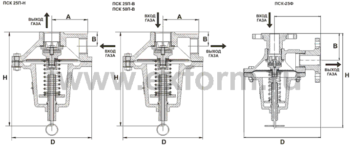
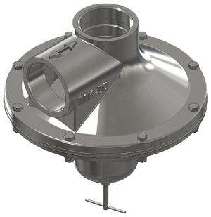
VALVE DEVICE
The appearance of PSK type valves is shown in the figure.The valve body is made in the form of a truncated cone with a flange, a seat and two holes with a cylindrical pipe thread 1 inch - version PSK-25P, 2 inches - version PSK-50P or with metric thread M36x1.5 - version PSK-25PF and M56x2 - version PSK -50PF. The seat is closed by a valve pos. 3 with rubber seal. The valve is assembled with membrane pos. 6, which is rigidly fixed between the valve and the plate pos. 7. In turn, the membrane is fixed between the body pos. 1 and cover pos. 2.
Spring pos. 4 is clamped between the membrane plate and stop pos. 8. By turning the adjusting screw pos. 5 the stop pos. 8, thus changing the force of the spring, which determines the setting of the valve for pressure within the given limits.
To check the operability, the valve is equipped with a forced opening mechanism, which is actuated by a rod pos. 9.

OPERATING PRINCIPLE OF THE VALVE
Gas from the network through the inlet of the body enters the valve cavity.At steady state, the controlled gas pressure within the established limits is balanced by a tuned spring, and the valve is hermetically closed.
When the gas pressure in the network (also in the valve cavity) exceeds the setting limit, the membrane, overcoming the forces of the spring, will fall along with the valve, while opening the gas outlet to the atmosphere through the discharge pipe.
The gas will be released until the pressure in the network drops below the set value, after which the valve closes under the action of the spring.
To check the operation of the valve, pull the linkage of the forced opening mechanism. This opens the valve. Repeat the operation 3-4 times.
PRICE, PRODUCTION TIME, DELIVERY TERMS
The price for valves PSK-25 and PSK-50 is provided upon official request to our company. The production time for relief valves does not exceed 20 days. Delivery is carried out to all regions of the Russian Federation, as well as to the territory of the CIS countries by any means of transport.The warranty period of operation is 36 months from the date of putting the product into operation, but not more than 48 months from the date of manufacture.
The appointed service life of the Valve is 35 years.


