The ring network is used in populated areas close in outline to a square or rectangle. In these networks, pipelines form one or more closed circuits - rings. Thanks to ringing, each section receives power from two or more lines, which significantly increases the reliability of the network and creates a number of other advantages. Ring networks ensure uninterrupted water supply even in case of accidents in individual sections: when the emergency section is turned off, the water supply to other network lines does not stop. They are less prone to accidents because... they do not experience strong hydraulic shocks. When a pipeline is quickly closed, the water flowing to it rushes into other lines of the network and the effect of the water hammer is reduced. The water in the network does not freeze, because even with a small amount of water, it circulates through all lines, carrying heat with it. Ring networks are usually slightly longer than dead-end networks, but are made of smaller diameter pipes. The cost of ring networks is slightly higher than dead-end networks. Due to their high reliability, they are widely used in water supply. They fully meet the requirements of fire-fighting water supply. After the water consumption of a settlement has been calculated, the circular distribution network is traced. This section proposes to calculate a two-ring distribution network. For this purpose, pipelines are drawn on the territory of the water supply facility (plan of the village), their ends and beginnings are connected, forming closed contours - rings, and water is supplied to large objects.
N.S. - pumping station
B - water tower
Then, as in the option with a dead-end network, nodes and sections are outlined on the ring network. Each section of the network is analyzed and measured. All results are summarized in Table 3. It should be noted that a feature of ring networks is that the distribution of water to water consumers occurs in almost all of its sections, which means that all of them are areas with travel costs. The only exceptions are those areas where it is clearly inappropriate to disassemble the water. These may be areas that supply water to large water consumers (for example, a bathhouse, a hospital, a medical facility, etc.). Further, when calculating ring networks, to simplify and facilitate hydraulic calculations, it is assumed that consumers draw water only at network nodes. This means that travel costs uniformly distributed along the length are replaced by equivalent concentrated nodal costs. Thus, nodal costs for each node of the ring water supply network are determined by the formula:
where q beats - specific network consumption, l/s per 1 linear meter;
∑l - total length of network track sections adjacent to a given node, m.
That is, the nodal flow rate is q knot. equal to half the sum of the travel costs of all sections adjacent to the node.
We summarize the calculation of nodal costs in Table 4.
You can check the correctness of the calculations and filling out the table as follows: the sum of all nodal expenses in column 4 of the table should be equal to the household expense - q xo 3., and the sum of all total nodal expenses in column 7 should be equal to the maximum second consumption of the village. Table
A design diagram of the ring distribution network is drawn (Figure 11), on which the values of total nodal flow rates from Table 4 are plotted at all its nodes on arrows pointing down. On the same diagram, only at the nodes of the rings, on arrows pointing up, the values are plotted total nodal costs, taking into account the water consumption consumed by individual large consumers. Then, on the design diagram, arrows indicate the direction of water movement along the branches of the network so that the water moves to the water supply facilities along the shortest path (without return movement). A very important task is to determine the estimated flow rates in all sections of the ring distribution network, from which the pipe diameters and pressure losses will subsequently be determined. When establishing the amount of costs passing through sections of the network, we are guided by two basic rules:
approximately one should be sent along equivalent highways
what amount of water;
Expenses assigned in this way are usually called first to
waste expenses. They are applied to the design diagram of the network.
Based on the first estimated flow rates, pipe diameters and pressure losses are calculated using the formulas given in the section “Calculation of dead-end networks.” After this, they check whether the known hydraulic condition of equality of pressure losses in the branches of the rings is met, namely, in each ring of the water supply network, the pressure losses along the branch, where the water moves in one direction, must be equal to the pressure losses in the other branch, where the water moves in the opposite direction. The algebraic sum of pressure losses in the ring is called discrepancy of the ring. In practice, to reduce calculations, a certain error is allowed, namely, the discrepancy is considered acceptable if its value does not exceed ± 0.5 m. If the value of the resulting discrepancy exceeds the permissible value, then the ring network must be linked. To link the network, i.e. to find the true flow rates along the lines, you should transfer part of the initial estimated flow rate from the overloaded branch, where the pressure loss is greater, to the underloaded one. To maintain the balance of flow rates in the nodes (the inflow to the node must remain equal to the outflow from the node), it is necessary to correct the flow rate in both branches by the same amount, i.e., if in an underloaded branch the calculated flow rate is increased by the value Aq, then Aq should be increased by the same value reduce the flow through an overloaded branch. The flow rate Aq is usually called correction expense. New expenses passing through sections of the ring network are called corrected expenses. Based on the corrected flow rates, new pressure losses in sections of the ring are determined and a new discrepancy is calculated. If the correction flow rate is set correctly, then after correcting the initial flow rates the ring will bind, i.e. the algebraic sum of pressure losses in the ring will not exceed the permissible value. If after the first correction the ring does not fit, continue tying.
22. Ring network with its main elements (examples). Modern methods hydraulic calculation. The ring network (Figure 10) is used in populated areas close in outline to a square or rectangle. In these networks, pipelines form one or more closed circuits - rings. Thanks to ringing, each section receives power from two or more lines, which significantly increases the reliability of the network and creates a number of other advantages. Ring networks ensure uninterrupted water supply even in case of accidents in individual sections: when the emergency section is turned off, the water supply to other network lines does not stop. They are less prone to accidents because... they do not experience strong hydraulic shocks. When a pipeline is quickly closed, the water flowing to it rushes into other lines of the network and the effect of the water hammer is reduced. The water in the network does not freeze, since even with a small drawdown it circulates through all lines, carrying heat with it. Ring networks are usually slightly longer than dead-end networks, but are made of smaller diameter pipes. The cost of ring networks is slightly higher than dead-end networks. Due to their high reliability, they are widely used in water supply. They fully meet the requirements of fire-fighting water supply.
Hydraulic calculation distribution network is carried out to determine the diameters of the pipes in all its sections and the pressure losses in them when supplying the calculated flow rate. If the water supply system is also intended for fire-fighting water supply, then a calibration calculation of the network is made to supply fire-fighting water flow with simultaneous domestic and drinking water consumption.
N.S. - pumping station
B - water tower
Figure - Diagram of the ring water supply network
After the water consumption of a settlement has been calculated, the circular distribution network is traced. This section proposes to calculate a two-ring distribution network. For this purpose, pipelines are drawn on the territory of the water supply facility (plan of the village), their ends and beginnings are connected, forming closed contours - rings, and water is supplied to large objects. Then, as in the option with a dead-end network, nodes and sections are outlined on the ring network. Each section of the network is analyzed and measured. All results are summarized in Table 3. It should be noted that a feature of ring networks is that the distribution of water to water consumers occurs in almost all of its sections, which means that all of them are areas with travel costs. The only exceptions are those areas where it is clearly inappropriate to disassemble the water. These may be areas that supply water to large water consumers (for example, a bathhouse, a hospital, a medical facility, etc.). Then the specific consumption of the water supply network is determined. We take it from the section on calculating a dead-end network. Further, when calculating ring networks, to simplify and facilitate hydraulic calculations, it is assumed that consumers draw water only at network nodes. This means that travel costs uniformly distributed along the length are replaced by equivalent concentrated nodal costs.
Thus, nodal costs for each node of the ring water supply network are determined by the formula:
q knot = (q beat ∙ Уl)/2
qsp - specific network consumption, l/s per 1 linear meter;
Ul put - the total length of all path sections of the network
That is, the nodal flow rate q node is equal to half the sum of the travel costs of all sections adjacent to the node.
We summarize the calculation of nodal costs in Table 8.
You can check the correctness of the calculations and filling out the table as follows: the sum of all nodal expenses in column 4 of Table 8 should be equal to the household expense - q household, and the sum of all total nodal expenses in column 7 should be equal to the maximum second consumption of the village. A design diagram of the ring distribution network is drawn, on which the values of the total node flow rates from the table are plotted at all its nodes on arrows pointing downwards. On the same diagram, only at the nodes of the rings, on the arrows pointing upward, the values of the total node flow rates are plotted, taking into account the water consumption consumed by individual large consumers. Then, on the design diagram, arrows indicate the direction of water movement along the branches of the network so that the water moves to the water supply facilities along the shortest path (without return movement). A very important task is to determine the estimated flow rates in all sections of the ring distribution network, from which the pipe diameters and pressure losses will subsequently be determined. When establishing the amount of costs passing through sections of the network, we are guided by two basic rules:
Approximately the same amount of water should be directed along equal mains;
The inflow to a node is equal to the outflow from that node plus the node flow.
![]() The expenses assigned in this way are usually called the first estimated expenses. They are applied to the design diagram of the network. Based on the first estimated flow rates, pipe diameters and pressure losses are calculated using the formulas given in the section “Calculation of dead-end networks.” After this, it is checked whether the known hydraulic condition of equality of pressure losses in the branches of the rings is met, namely, in each ring of the water supply network, the pressure losses along the branch, where the water moves in one direction, must be equal to the pressure losses in the other branch, where the water moves in the opposite direction. The algebraic sum of pressure losses in a ring is called the ring discrepancy. In practice, to reduce calculations, a certain error is allowed, namely, the discrepancy is considered acceptable if its value does not exceed ± 0.5 m. If the value of the resulting discrepancy exceeds the permissible value, then the ring network must be linked. To link the network, i.e. to find the true flow rates along the lines, you should transfer part of the initial estimated flow rate from the overloaded branch, where the pressure loss is greater, to the underloaded one. To maintain a balance of flow rates in the nodes (the inflow to the node must remain equal to the outflow from the node), it is necessary to correct the flow rate in both branches by the same amount, i.e., if in an underloaded branch the estimated flow rate is increased by the amount , then the flow rate should be reduced by the same amount passing along an overloaded branch. The flow rate is usually called the correction flow rate. New costs passing through sections of the ring network are called corrected costs. Based on the corrected flow rates, new pressure losses in sections of the ring are determined and a new discrepancy is calculated. If the correction flow rate is set correctly, then after correcting the initial flow rates the ring will bind, i.e. the algebraic sum of pressure losses in the ring will not exceed the permissible value. If after the first correction the ring does not fit, continue tying.
The expenses assigned in this way are usually called the first estimated expenses. They are applied to the design diagram of the network. Based on the first estimated flow rates, pipe diameters and pressure losses are calculated using the formulas given in the section “Calculation of dead-end networks.” After this, it is checked whether the known hydraulic condition of equality of pressure losses in the branches of the rings is met, namely, in each ring of the water supply network, the pressure losses along the branch, where the water moves in one direction, must be equal to the pressure losses in the other branch, where the water moves in the opposite direction. The algebraic sum of pressure losses in a ring is called the ring discrepancy. In practice, to reduce calculations, a certain error is allowed, namely, the discrepancy is considered acceptable if its value does not exceed ± 0.5 m. If the value of the resulting discrepancy exceeds the permissible value, then the ring network must be linked. To link the network, i.e. to find the true flow rates along the lines, you should transfer part of the initial estimated flow rate from the overloaded branch, where the pressure loss is greater, to the underloaded one. To maintain a balance of flow rates in the nodes (the inflow to the node must remain equal to the outflow from the node), it is necessary to correct the flow rate in both branches by the same amount, i.e., if in an underloaded branch the estimated flow rate is increased by the amount , then the flow rate should be reduced by the same amount passing along an overloaded branch. The flow rate is usually called the correction flow rate. New costs passing through sections of the ring network are called corrected costs. Based on the corrected flow rates, new pressure losses in sections of the ring are determined and a new discrepancy is calculated. If the correction flow rate is set correctly, then after correcting the initial flow rates the ring will bind, i.e. the algebraic sum of pressure losses in the ring will not exceed the permissible value. If after the first correction the ring does not fit, continue tying.
23. Extraction of water from underground sources. The composition of structures taking into account the quality of groundwater. Groundwater occurs at different depths and in different rocks. Possessing high sanitary qualities, these waters are especially valuable for domestic and drinking water supply in populated areas. Of greatest interest are the waters of pressure aquifers, covered on top by waterproof rocks that protect groundwater from the entry of any pollution from the surface of the earth. However, for water supply purposes, non-pressure groundwater with a free surface, contained in layers that do not have a waterproof roof, is often used. In addition, for water supply purposes, spring (spring) waters are used, i.e., underground waters that independently come to the surface of the earth. Finally, in some cases, so-called mine and mine waters are used for industrial water supply, i.e., underground waters entering drainage structures When dealing with groundwater, the following types of structures are used:
1) tube boring wells (wells);
2) mine wells;
3) horizontal watersheds;
4) radial catchments;
5) structures for capturing spring water.
Tube wells are constructed by drilling vertical cylindrical channels in the ground - wells. In most rocks, the walls of the wells have to be reinforced with casing (most often steel) pipes, forming a tube well. Tube wells are usually used when aquifers are relatively deep and the thickness of these layers is significant. In this regard, their characteristic feature is a relatively small diameter (facilitating the passage of large rock masses) and a relatively large length of the drainage part. Tube wells can be used to receive both free-flowing and pressurized groundwater. In both cases, they can be brought to the underlying water-resistant layer - “perfect wells” or end in the thickness of the aquifer - “imperfect wells”. The design of a tube well depends on the depth of groundwater, the nature of the passable rocks and the drilling method. In turn, the drilling method is adopted depending on the required depth of the well.
Mine wells are most often used to receive relatively shallow water (usually at a depth of no more than 20 m) from unconfined aquifers. In rare cases, these wells are used to receive low-pressure water (with insignificant depth and insignificant thickness of pressure aquifers). Typically, water is received into mine wells through their bottom and partly their walls. Mine wells are used to receive small amounts of water for individual use, as well as in water supply to rural areas, in temporary water supply systems, etc. Mine wells can be concrete, reinforced concrete, stone (made of brick or rubble stone) and wooden (log-frame). If the diameter of the wells is small, they can be made prefabricated from reinforced concrete rings. Mine wells are usually built using the downward method.
Horizontal catchments are used when the aquifer is shallow (up to 5-8 m) and its thickness is relatively small. They are drainages different types or drainage galleries laid within the aquifer (usually directly on the underlying aquitard). The drainage device is often located along a line perpendicular to the direction of movement of the ground flow. Water that comes from the ground into drainage pipes or galleries, is fed through them into a collecting well, from where it is pumped out by pumps. All designs of horizontal drainage basins can be divided into the following three groups:
1) trench catchment areas backfilled with stone or crushed stone;
2) tubular catchments,
3) drainage galleries
The radial catchment area is an original and efficient water intake structure, successfully used to receive sub-channel water. Water is collected by horizontal tubular drains located within the aquifers, radially connected to a prefabricated shaft well. Radial water intakes are also used for the intake of groundwater that does not have recharge from open reservoirs, provided that the aquifers of relatively small thickness lie at a depth of no more than 15-20 m. Radial drains are made from perforated (slotted) steel pipes and are arranged by pressing (by links) from the inside mine well(or drilling). Some methods for laying radial drains involve pre-punching casing pipes into which drainage pipes are then inserted. After installing the latter, the casing pipes are removed. In other methods, drainage pipes equipped with a parabolic head are pressed directly, to which water is supplied under pressure, coming out through the cracks in the head and eroding the soil. The pulp is removed through a drain pipe into the shaft.
Springs, or springs, are natural outlets of groundwater to the surface. Transparency, high sanitary qualities, and also relatively simple ways obtaining spring water led to its widespread use for drinking water supply purposes. In addition to the huge number of small settlements that use spring water, even a number of large cities have water supply systems based on feeding them with spring water. For large water pipelines, several groups of powerful springs are usually used simultaneously. There are two types of springs - ascending and descending. The former are formed when pressure water penetrates the surface layers of the soil as a result of a violation of the strength of the overlying waterproof rocks. The latter are formed as a result of the pinching out onto the surface of the earth of free-flowing aquifers resting on waterproof rocks. Structures for receiving spring water (in accordance with the nature of their work) are called capture structures, and the process of collecting spring water is called spring capture. These structures have various device for the two named types of springs. To capture rising springs, water intake structures are made in the form of a reservoir or shaft, built above the place of the most intense release of spring water. Capturing of descending springs is carried out by constructing unique receiving chambers located in the place of the most intense release of spring water. In some cases, structures in the form of “jumpers”, retaining walls, etc. are installed perpendicular to the main direction of movement of spring water to intercept it and direct it to the receiving chamber. Sometimes horizontal drainage pipes or galleries are laid along these jumpers, collecting water and facilitating its transportation to the receiving chamber camera.
Send your good work in the knowledge base is simple. Use the form below
Students, graduate students, young scientists who use the knowledge base in their studies and work will be very grateful to you.
Posted on http://www.allbest.ru
Introduction
Conclusion
Bibliography
Introduction
A water supply and sanitation system is necessary for comfortable housing; right choice water supply and sanitation schemes ensure a reliable, constant supply of water to consumers and disposal of waste water. Purpose course work is: determination of the estimated water flow, hydraulic calculation of the internal water supply network, selection of a water meter, determination of the estimated waste fluid flow, assignment of diameters sewer pipes, determination of the capacity of sewer outlets and yard sewer network.
According to the assignment of the course work, it is necessary to design water supply and sanitation systems for a 6-story, 36-apartment residential building in Mogilev:
Floor height - 3 m,
Basement height - 2.8 m.
First floor elevation - 97 m,
Ground surface elevation - 96 m.
The city water supply system with a diameter of 250 mm is laid at a depth of 94 m, the city sewerage network with a diameter of 350 mm is laid at a depth of 93 m.
The depth of penetration into soil at zero temperature is 1.2 m.
The guaranteed pressure in the city water supply is 32.0 m.
1. Design of internal water supply
The internal water supply of the designed building consists of an inlet located to the left of the building on the side of the city water supply, one water metering unit, a main line, risers and connections to water distribution devices. When designing an internal water supply, we follow the instructions.
We depict water risers in circles and designate them: StV1-1, StV1-2, etc.
From the city water supply on the plan we show the entry of the water supply into the building; The water supply is entered at the shortest distance perpendicular to the wall of the building. The inlet ends with a water meter installed inside the building.
At the point where the input connects to external network for the city water supply we arrange a well with a valve installed in it.
We draw the input line on the general plan of the site, indicating its length and diameter and indicating the position of the well in which it is planned to connect the input to the street network.
The water metering unit is located immediately behind the wall inside the basement. It consists of a water meter, shut-off valves in the form of gate valves or valves installed on each side of the meter, a control valve, connecting fittings and pipes. We use a high-speed vane water meter VK.
Guided by the location of the water risers and the location of the input, we trace the water distribution main. From the distribution main we make connections d=25mm to watering taps, placed in niches of external walls measuring 250x300 mm at a height of 200-300 mm from the sidewalk at the rate of one watering tap per 60-70 m of the building perimeter.
In accordance with the placement of the water risers, distribution main, water meter unit and input, we draw an axonometric diagram of the internal water supply on a scale of 1:100 along all three axes.
We install shut-off valves at the base of all risers in the building. Also shut-off valves installed on all branches from the main line, on branches to each apartment, on connections to flushing sewerage devices, in front of the outdoor watering taps. We install valves on pipelines with a nominal bore of less than 50 mm.
The internal water supply diagram is the basis for the hydraulic calculation of the water supply network.
1.1 Hydraulic calculation internal network water supply
The water supply for domestic and drinking purposes is calculated for the case of maximum household water consumption. The main purpose of the hydraulic calculation of the water supply network is to determine the most economical pipe diameters for passing the calculated costs. The calculation is performed using a dictation device. We divide the selected calculated direction of water movement into calculated sections. For the design section we take a part of the network with a constant flow rate and diameter. Initially, we determine the costs for each section, and then we make a hydraulic calculation. Calculated maximum expenses water in individual sections of the internal water supply network depends on the number of water taps installed on them and simultaneously operating and on the flow of water flowing through these devices.
The criterion for the normal operation of the water supply network is the supply of standard flow under the operating standard pressure to the dictating water tap. The ultimate task of hydraulic calculation is to determine the required pressure to ensure normal operation of all points of the water supply network. Hydraulic calculations of the water supply network should be made based on the maximum second flow rate. The maximum second flow rate q, l/s, in the calculated area should be determined by the formula:
where q0 is the standard flow rate for one device, l/s.
The value of q0 is taken according to the mandatory Appendix 3. The value b is taken according to Appendix 4.
The probability of operation of devices P for network sections serving groups of identical consumers in buildings or structures should be determined by the formula:
where is the rate of water consumption, l, by one consumer per hour of greatest water consumption, which should be taken in accordance with Appendix 3 of SNiP 2.04.01-85; U is the total number of identical consumers in the building; N is the total number of devices serving U consumers.
Number of consumers for residential buildings
where F is living area; f- sanitary standard living space per person.
In residential and public buildings and structures for which there is no information on water consumption and technical specifications sanitary appliances, it is allowed to accept:
q0 = 0.3 l/s; =5.6 l/h; f = 12 m2.
After determining the estimated costs, we assign the diameters of the pipes in the calculated sections based on the most economical speeds of water movement. In pipelines of domestic and drinking water supply systems, according to the rules, the speed of water movement should not exceed 3 m/s. To select diameters, use hydraulic calculation tables for pipes.
We summarize the entire calculation of the internal water supply in Table 1.
Table 1 - Hydraulic calculation of internal water supply
|
Settlement area number |
|||||||||||
The sum of losses along the length is 16.963 m, input losses are 1.6279 m.
1.2 Selecting a water meter
We select a water meter (water meter) to pass the maximum calculated water flow (excluding fire-fighting flow), which should not exceed the highest (short-term) flow for a given water meter.
Data for selecting a high-speed water meter are given in table. IV.I and table 4.
Head loss hs, m water. Art., in a vane water meter is determined by the formula:
where S is the resistance of the water meter, which is taken according to the table. IV.I and table 4; S=1.3m s2/l2, q - water flow flowing through the water meter, l/s, the value is taken from Table 1.
hsv = 1.3 (0.695)2 = 0.628 m.
The water meter is selected correctly, since the pressure loss ranges from 0.5 m to 2.5 m.
1.3 Determination of required pressure
After a hydraulic calculation of the internal water supply network, we determine the amount of pressure required to supply the standard water flow to the dictating water distribution device at the highest domestic and drinking consumption, taking into account the pressure loss to overcome resistance along the path of water movement.
where Hg is the geometric height of the water supply from the point of connection of the input to the external network to the dictating water tap; Hg=16.8 m.
Figure 1 - Determining the required water pressure
hвв - pressure loss in the inlet; taken from Table 1, hвв = 1.6279 m. hsv - pressure loss in the water meter; the value will be determined by calculation in section 1.2; hsv = 0.628 m. ?hl is the sum of pressure losses along the length of the design direction; determined from Table 1, ?hl = 16.96 m. 1.3 - coefficient taking into account pressure losses in local resistances, which for drinking water supply networks of residential and public buildings are taken in the amount of 30% of the pressure losses along the length; Hf is the free pressure at the dictating water outlet, taken from Appendix 2, Hf=3 m.
Htr = 16.8+1.627+0.628+1.3 16.96+3 = 44.10 m.
Since Htr = 44.10 m>Hgar = 32.0 m, a booster pumping unit is required.
2. Design of internal and yard sewerage
2.1 Selecting a system and scheme for internal yard sewerage
System internal sewerage designed for drainage Wastewater from buildings to external sewer networks. The design of internal sewerage is carried out in accordance with.
The internal sewerage network consists of wastewater receivers, outlet pipes, sewer risers, outlets and a yard network.
We design the internal sewerage network in the following order: we draw sewer risers on the building plans in accordance with the placement of sanitary fixtures. We mark sewer risers on all plans symbols StK1-1, StK1-2, etc.
From sanitary fixtures to risers we trace the lines of drain pipes, indicating the diameters and slopes of the pipes on an axonometric diagram. From the risers we trace outlets through the wall of the building and show the locations of the wells using the yard sewer line. On the outlets we indicate the diameter, length and slope of the pipes. We lay sections of the sewer network in a straight line. We change the direction of laying the sewer pipeline and connect the devices using fittings. We denote the releases: Release K1-1, K1-2, etc.
We place sewer risers that transport wastewater from the drain lines to the lower part of the building in the bathrooms opposite the toilets at a distance of 0.8 m from the wall. To clean the risers, we install audits on the first, third and fifth floors, and we place the audits at a height of 1 m from the floor to the center of the audit, but less than 0.15 m above the side of the connected device.
We make the transition of the riser to the outlet smooth with the help of bends. We end the outlet with a manhole for the yard sewer network.
The length of the outlet from the building wall to the yard well is 5 m; we place the sewer outlets on one side of the building perpendicular to the plane of the external walls.
We lay the yard sewerage network parallel to the outer walls of the building along the shortest path to the street sewer with the smallest depth of pipes. The depth of the yard network is determined by the mark of the deepest (dictating) outlet in the building.
On the general plan of the site we draw a yard sewer line with all inspection, rotary and control wells. We designate inspection wells: KK1, KK2, KK3, etc. We install a KK inspection well 1m deep into the yard. At the point where the yard sewer line joins the city sewer, we depict the city sewer well GKK. On all sections of the yard sewer line we mark the diameters of the pipes and the lengths of the sections.
Selection of sewer risers.
The diameter of the sewer riser is selected depending on the estimated waste liquid flow rate and the largest diameter of the floor pipeline that drains wastewater from the device having the maximum capacity. The sewer riser must have the same diameter throughout its entire height, but not the largest diameter of the floor branches connected to this riser [ largest diameter outlet pipeline d=100 mm has a toilet].
The internal sewerage network is ventilated through risers, the exhaust part of which is discharged 0.5 m above the roof of the building.
2.2 Determination of estimated wastewater flow rates
The diameters of the internal and yard sewerage systems are determined based on the estimated wastewater flow rates by area.
The estimated amount of wastewater from individual sanitary fixtures, as well as the diameters of the drain lines, are determined using Appendix 2.
The amount of wastewater entering the sewer system in a residential building depends on the number, type and simultaneous operation of sanitary fixtures installed in them. To determine the estimated wastewater flow rates qs, l/s, entering the sewer system from a group of sanitary fixtures, at qtot? 8 l/s we use the formula:
,
where qtot is the total maximum calculated second water flow rate in cold and hot water supply networks, qs0 is the flow rate of wastewater from sanitary fixtures with maximum drainage, l/s, accepted in accordance with the mandatory Appendix 2.
For a residential building, the highest wastewater flow rate from the device (flushing the toilet tank) is qs0 = 1.6 l/s.
Wastewater consumption is determined by sewer risers and horizontal sections pipelines located between risers and wells.
After determining the estimated wastewater flow rates for sewer risers and horizontal sections of sewer networks, we assign the diameters of sewer pipes.
2.3 Construction of a longitudinal profile of a yard sewerage system
We take the necessary absolute elevations of the ground surface and the bottom of the pipe tray from Table 2 - calculation of the sewer network.
The longitudinal profile of the yard sewer network is drawn next to the general plan with a horizontal scale of 1:500 and a vertical scale of 1:100. It includes all sections of the yard sewer line, as well as the connecting line from the control well to the well on the street sewer. On the profile we show the marks of the ground surface and pipe trays, slopes, distances between the axes of the wells, and depths of the wells.
2.4 Hydraulic calculation of outlets and yard sewerage pipelines
We carry out a hydraulic calculation of the sewer network to check the correctness of the choice of diameter, pipes and slopes. They must ensure that the calculated flow rates are passed at a speed greater than the self-cleaning speed, equal to 0.72 m/s. At a speed less than 0.72 m/s, solid suspension may be deposited and the sewer line may become clogged.
We select pipes for the yard drainage network according to the application.
Based on the estimated flow rate and diameter, we select the slope of the sewer pipes.
Outlets that drain wastewater from the risers outside the buildings into the yard sewer network are laid with a slope of 0.02 with a pipe diameter of 100 mm.
We design the diameter of the outlet to be no less than the diameter of the largest of the risers connected to it.
The diameter of the pipes of the yard and intra-block network is taken to be 150 mm. We try to ensure that the yard network has the same slope throughout. Minimum slopes when laying a yard network, we take d = 150 mm i = 0.007 for pipes.
The greatest slope of the sewer network should not exceed 0.15. The calculation of the sewer network is summarized in Table 2.
The design elevation of the city sewerage network is 93.00 m.
Table 2 - Hydraulic calculation of yard sewerage
|
Plot number |
Ground marks |
Tray marks |
||||||||||||
Conclusion
As a result of course work on water supply and sanitation of a residential building, an internal water supply network, as well as an internal and yard sewerage network were designed in accordance with sanitary and hygienic requirements. As a result of the hydraulic calculation of the internal water supply network, pipes with a diameter of 20, 25, 32 mm were adopted, the input diameter was 50 mm, the pressure loss along the length was 16.96 m. A water meter was selected for the water supply system - a vane water meter with a resistance S = 1.3 m s2/ l2. When determining the required pressure, it was concluded that it was necessary to use a booster unit. When calculating the internal and yard sewerage system, the design and location of the sewer risers of the inspection wells were chosen; the wastewater flow through the building was 4.916 l/s. During the hydraulic calculation of the outlets and pipelines of the yard sewerage system, the required diameters and slopes of the pipes were selected, taking into account the speed of movement of wastewater and the filling of the pipes. Diameter sewer outlets for the building d=100 mm, yard sewerage d=150 mm. The slope of the pipeline tray is 0.018. All calculations were made in accordance with the standards established in.
hydraulic plumbing sewer
Bibliography
1. SNiP 2.04.01-85 Internal water supply and sewerage of buildings. - M.: Stroyizdat. 1986.
2. V.I. Kalitsun et al. “Hydraulics, water supply and sewerage” - M.: Stroyizdat. 1980.
3. Pisarik M.N. Water supply and sewerage of a residential building. Method of instructions for completing coursework, according to engineering networks, equipment of buildings and structures. - Gomel: BelGUT. 1990.
4. Kedrov V.S., Lovtsov B.N. Sanitary equipment of buildings. - M.: Stroyizdat. 1989.
5. Palgunov P.P., Isaev V.N. Sanitary installations and gas supply of buildings. - M.: Stroyizdat. 1991.
Posted on Allbest.ru
...Similar documents
Description of the design solution of the designed internal water supply network and input. Axonometric diagram and hydraulic calculation of the internal water supply network. Yard sewer network and wastewater receivers. Calculation of internal sewerage.
course work, added 01/28/2014
Selection of a water meter taking into account the maximum daily water flow. The building's internal domestic drainage network system. Determination of the required required pressure in the water supply system. Hydraulic calculation of water supply network and yard sewerage.
course work, added 12/04/2012
Hydraulic calculation of the water supply network and intra-block sewerage network. Internal sewage system and their main elements. Materials and devices of internal drains, throughput. Specification of water supply and sewerage systems.
course work, added 09/30/2010
Design of building cold water supply systems. Hydraulic calculation of internal water supply network. Determination of estimated water flow rates, pipe diameters and pressure losses. Installation of internal sewerage networks. Yard sewer network.
course work, added 03/03/2015
Selection and justification of a fundamental water supply system. Specification of materials and equipment, hydraulic calculations and maximum costs of the water supply network. Selection of a water meter. Design of sewer risers and outlets from the building.
course work, added 06/17/2011
Design and calculation of internal water supply systems of a building. Construction of an axonometric diagram of the building's water supply network. Hydraulic calculation of water supply network. Installation of an internal sewer network. Determination of estimated wastewater flow rates.
test, added 09/06/2010
Choosing a building's cold water supply system. Installation of internal water supply network, pipe depth and network routing. Hydraulic calculation of internal pipeline, determination of pressure. Design of internal and yard sewage system of a building.
course work, added 11/02/2011
Design of the building's internal water supply network. Selection of water metering device. Determining the required pressure for water supply to a residential building. Analysis of the structure of the internal and yard sewer network. Hydraulic calculation of yard sewerage.
test, added 11/12/2014
Natural and climatic characteristics of the area where the city of Narovlya is located. Determination of water consumption for household and drinking needs of the population. Distribution of water consumption in a populated area by hour of the day. Hydraulic calculation of distribution network and water pipelines.
course work, added 01/28/2016
Hydraulic calculation of water supply and sewerage of a residential building. Determination of the required pressure, selection of a water meter. Design of internal sewerage for a residential building. Placement of sewer risers. Determining the marks of sewer pipe trays.
The design diagram of the water supply network repeats the network configuration in plan. It shows design nodes - the point of water supply from PS-2, the point of connection of the water tower, the points of separation and merging of flows, the points of connection of the largest consumers.
According to the methodology adopted for calculation water supply networks, water is collected from the network only at settlement nodes. The value of these nodal costs is determined according to the water consumption schedule separately for each water consumer.
Hydraulic calculation of the water supply system in fire extinguishing mode is performed on the basis of the design diagram for the hour of maximum water consumption and the corresponding pipeline diameters. In addition to the collection of water for domestic drinking and industrial needs, the costs of fire extinguishing in the most unprofitable (highest located and most distant from the power point) network nodes are added. The purpose of the calculation is to check the water supply network for the passage of increased water flows, to determine the pressure losses and the required pressure at the starting point of the network (at PS-2). If the pump selected for normal operation is not capable of providing the parameters required for fire extinguishing (Q and H), an additional fire pump may be provided.
There are two stages of fire extinguishing. At the first stage (its duration is 10 minutes), NS-2 operates in normal mode, the fire water supply in the water tower tank is consumed, i.e., the water supply to the network from the water tower increases by the amount of water consumption for fire extinguishing.
At the second stage, it is considered that the water supply in the tank is completely used up, and supply is carried out only from fire pumps at PS-2. Usually only the second stage of fire extinguishing is calculated. Water supply to the network from PS-2, l/s, is determined by the formula
where is the total water consumption per hour of maximum water consumption by all consumers according to the water consumption sheet, l/s; - water consumption for fire extinguishing for the estimated number of fires, l/s, according to formula (4.1).
Hydraulic calculations of dead-end water supply networks and dead-end sections of ring networks are performed using the same formulas as the calculation of pump-hose systems (2.1)-(2.3). Water consumption in a network section is equal to the sum of the node flow rates of all nodes receiving water in this section. Data on the hydraulic resistance of water supply network pipes are given in table. 4.1.
Table 4.1
Values of calculated resistivity of pipelines A, s2/m6, (for Q, m3/s) at v = 1.2 m/s
|
Diameter, mm |
Steel pipes |
Cast iron pipes |
Asbestos cement pipes |
Unlike a dead-end ring network, it is a system of parallel connected mains; the distribution of water between these mains requires a separate calculation. In this case, Kirchhoff's laws are used.
According to the first law, the algebraic sum of costs at each node is equal to zero - the flow rate of water entering the node is equal to the flow rate of water leaving the node.
According to the second law, the algebraic sum of pressure losses in the ring is equal to zero - the sum of pressure losses in sections with a clockwise direction of movement is equal to the sum of pressure losses in sections with a counterclockwise direction of movement.
In engineering practice, when hydraulically calculating a water supply system in fire extinguishing mode, preliminary flow distribution is carried out across sections of the ring network. At the same time, the fulfillment of Kirchhoff's first law is ensured. Next, a hydraulic calculation of all sections of the ring network is performed, and the fulfillment of the second law is checked. Since the preliminary flow distribution was carried out on the basis of speculative considerations, the algebraic sum of pressure losses in the ring, called the discrepancy Dh, is not only not equal to zero, but can be quite significant. Redistribution of threads is required. To obtain the equality Sh = 0 or Dh = 0 for sections of the ring in the direction opposite to the sign of the discrepancy, the linking flow rate Dq is passed, which is approximately determined

where s = Al - hydraulic characteristics of ring sections; q - preliminary costs at the sites.
New updated costs at the sites are determined
In a lot ring networks Using this method, correction costs for each ring and updated costs for all sections are determined, but due to the approximate nature of formula (4.3) and the presence of adjacent sections included simultaneously in two adjacent rings, it is not possible to immediately achieve a zero discrepancy Dh = 0 in all rings. It is required to carry out several rounds of linking calculations. At large quantities rings, such calculations are very labor-intensive, and to perform them they are used computer programs. The accuracy of the calculations is considered sufficient if the discrepancy in all rings does not exceed 0.5 m.
Based on the results of network calculations in fire extinguishing mode, the required fire pump pressure is determined
where is the ground elevation at the dictating point - usually the node where the flows converge in the fire extinguishing mode or the highest point, m; - the required free pressure when extinguishing a fire is assumed to be 10 m; - total pressure loss in fire extinguishing mode from PS-2 to the dictating point; - the minimum water level mark in the RHF, m, is assigned 2...4 m below the ground surface in the area of NS-2.
The performance of the fire pump must meet the needs of all water consumers during the hour of maximum water consumption, plus the total estimated fire water consumption, determined by formula (4.2).
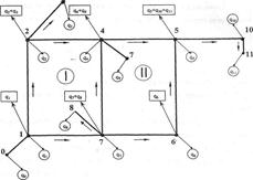
Example. Perform calculations in the fire extinguishing mode of the main water supply network of the village, determine the parameters of the fire pump.
Initial data. The population of the village is 20 thousand people. Development of buildings up to two floors inclusive. Residential and public buildings have volumes of up to 1 thousand m3. Industrial buildings without lanterns, 50 m wide, have a volume of 10 thousand m3. The degree of fire resistance of buildings is II, category of premises according to fire safety- B. The general plan of the village, the diagram of water supply networks and diameters are shown in Fig. 4.3, nodal costs - in Fig. 4.4, cast iron pipes. NS-2 is located 2 km from the village at a ground level of 40.0 m, the water pipeline is made in 2 threads. The total water consumption for household, drinking and industrial needs per hour of maximum water consumption is 170.0 l/s.
fire extinguishing hydraulic water network
Rice. 4.3. Water supply network diagram
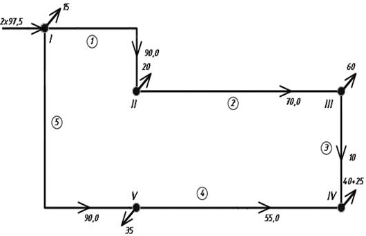
Rice. 4.4. Preliminary design diagram of the water supply network for fire fighting
Solution. In accordance with the number of residents according to table. 5 adj. 1 the estimated number of simultaneous fires is established - 2. Water consumption for external fire extinguishing per fire is 10 l/s. According to the table 6 adj. 1, the water consumption for one fire in residential and public buildings is set at 10 l/s, which does not exceed the previously assigned consumption. In accordance with the specified parameters production premises according to table 7 adj. 1 the water consumption for external fire extinguishing of industrial buildings is assigned to 15 l/s. Thus, two simultaneous fires are considered in the village, one at an industrial enterprise with a fire extinguishing flow rate of 15 l/s, the second in a residential area - 10 l/s. Water collection for extinguishing both fires is assigned to node IV - the most distant from the supply point (node I) and located at a fairly high ground level (50.7 m). In the design diagram of the network (Fig. 4.4), the flow rate for extinguishing two fires is added to the nodal flow rate in node IV. The total water supply in fire extinguishing mode is 195.0 l/s.
Hydraulic calculation of a water pipeline comes down to determining the pressure loss when the calculated flow rate is missed. Both lines of the water pipeline have the same diameters of 300 mm and length - the total flow is distributed equally at 97.5 l/s. According to the table 4.1, the specific resistance of the pipeline is determined to be A = 0.9485 s2/m6. The pressure loss in the water pipeline is determined by formula (2.2).
Based on an analysis of the configuration of the ring network and the values of nodal flow rates, a preliminary flow distribution was performed in compliance with Kirchhoff’s 1st law (see Fig. 4.4). The hydraulic calculation is performed in tabular form (Table 4.2). In sections 4 and 5, costs are directed counterclockwise and are taken into account with a minus sign.
Table 4.2
Hydraulic calculation table
|
Pre-flow distribution |
|||||||||
|
SUM(ABOVE) 0.693 |
The calculation showed that during the preliminary flow distribution, the right branch along the water flow was overloaded, and the discrepancy of 4.08 m exceeds the permissible value of 0.5 m. The linking flow rate was determined by formula (4.3).

Expenses are adjusted by the value Dq in a clockwise direction (Table 4.3). The calculation is designed as a continuation of the previous table.
Table 4.3
Continuation of the hydraulic calculation table
The discrepancy value is satisfactory, the resulting costs can be considered calculated. The calculation results are presented in Fig. 4.5.
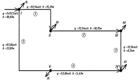
Rice. 4.5. Final design diagram of the water supply network for fire fighting
The required fire pump pressure is determined by formula (4.5). At the same time, the ground elevation at the dictating point IV horizontally on the general plan is determined to be 50.7 m, the minimum water level in the RHF is assigned 2 m below the ground elevation according to the initial data, 38.0 m. The total pressure loss in the fire extinguishing mode from NS-2 to dictating points are defined as the sum of pressure losses in the water pipeline and losses in any branch of the ring network from the supply point to the fire extinguishing point.
Based on this pressure and the previously calculated performance of 195 l/s, the brand of fire pump is selected.
"Hydraulic calculation of ring water supply networks"
1. Initial data
.1 Description of water supply design scheme
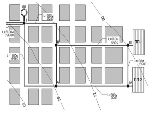
It is necessary to calculate the water supply system of a populated area and a railway station.
The water supply to the railway settlement is provided by groundwater.
Water from the drainage gallery 1 enters the receiving tank 2 and from there to pumping station 3 is supplied through a pressure conduit to the water tower 4, from which it then enters the ring water supply network 4-5-6-7-8-9, supplying water to the settlement and the following industrial and household water consumers:
Figure 1. Water supply diagram:
Source of water supply
Receiving tank
Pumping station
Water tower
Station building and cranes for refueling passenger cars
Locomotive depot
Industrial enterprise No. 1
Industrial enterprise No. 2
Industrial enterprise No. 3
Water consumption for household and drinking needs and watering streets and green spaces is evenly distributed along the axis of the distribution network.
1.2 Initial data for calculation
1.The estimated number of residents in the village is 22,170 people. 2.The number of floors of the building is 10 floors. .The buildings of the settlement are equipped with internal water supply and sewerage without bathtubs. .At the station, 317 cars are filled with water every day. .Maximum daily water consumption: industrial enterprises: No. 1 - 3217, m 3/day No. 2 - 3717, m 3/day No. 3 - 4217, m 3/day Locomotive depot - 517, m 3/day 6.Length of pipe sections: Ground marks: Pumping station (point 4) - 264 m At point 5 - 282 m At point 8 - 274 m At point 6 - 278 m Water marks in the receiving tank are 258 m. 2.Dividing the estimated daily water consumption
The main water consumer in towns and cities is the population, which uses water for household and drinking needs. The amount of water for these needs depends on the degree of sanitary equipment in residential buildings, the development of a network of public service enterprises and the general improvement of the city. Determination of daily water consumption Q days :
· Locality: Q Wed =N*q, m 3
Q max =N*q*K max , m 3
where N= 22170 people; TO max = 1.2; TO min = 0,8
q= 0.2 m 3/day Q Wed =22170*0.2=4434 m 3
Q max =22170*0.2*1.2=5320.8 m 3
Q min =N*q*K min = 22170*0.2*0.8=3547.2 m 3
The highest calculated daily flow rate is the basis for the calculation of most water supply system structures. · Watering streets and green spaces: Q=N i *q floor m 3/day, where N i - number of residents in the village; q floor - norm of water for irrigation per inhabitant; q floor =0.07 m 3/day; Q=22170*0.07=1551.9 m 3/day · Refueling of wagons: Q=N*q m 3/day, where N is the number of cars; q=1 m 3/day; Q =317*1=317 m 3/day Estimated daily water consumption No. Name of consumers Units of measurement Number of consumers Water consumption rate, m 3/dayDaily consumption, m 3/day Average exact Per day max. Average daily Per day max. 1 Settlement people 221700.20.2*1.2=0.2344345320.82 Watering streets and green areas. Plantings people.221700.070.071551.91551.93Industrial enterprise No.1pred.132173217321732174Industrial enterprise No.2pred.137173717371737175Industrial enterprise No.3pred.142174217421742176Locomotive depot.15175 175175177 Station building 1151515158 Refueling wagons wagon 317113173179 Fire extinguishing fire 20.025*3600*3=270270540540 å 19412,7
Free pressure for domestic and drinking water supply is determined by the formula: N St. =10+4(n-1) m. water. Art. (1) where n is the number of floors of the building. N St. =10+4(10-1)=46 m.water. Art. accept N St. =46 m. water. Art. 3. Determination of estimated second water consumption
.1 Calculation for 24-hour operating facilities water supply settlement Estimated second water consumption is determined in l/day for individual categories of water consumption. It should be taken into account that some water consumption points operate around the clock (village, industrial enterprise, railway station, depot), while others operate less than a day (watering streets and green spaces, refueling cars at the station). The second consumption of water consumption facilities operating around the clock is determined by the formula: q sec =K hour *Q max days /86400 m 3/s (2) where: K hour - coefficient of hourly unevenness (k hour =1,56),max - daily consumption on the day of greatest water consumption; The number of seconds in a day. household and drinking needs: q sec =1.5*5320.8/86400=0.096 m 3/With q sec =1.5*3217/86400=0.0558 m 3/With industrial enterprise No. 2: q sec =1.5*3717/86400=0.0645m 3/With industrial enterprise No. 3: q sec =1.5*4217/86400=0.0732 m 3/With locomotive depot: q sec =1.5*517/86400=0.0089 m 3/With q sec =1.5*15/86400=0.00026 m 3/With 3.2 Calculation for periodically operating objects
Estimated second costs for periodically operating objects are determined by the formula: q sec =Q max days /(3600*T consumption ), m 3/s (3) where: T consumption - period of operation of the object in hours. Number of seconds in an hour. watering streets and green spaces: T consumption =8 hours q sec =1551.9/(3600*8)=0.0538 m 3/With Refueling of wagons: T consumption =n trains *t trains ,
where: n trains - number of trains; trains =N carriages /15=317/15=21;trains - refueling time for one train (0.5 hours); T consumption =21*0.5=10 hours. q sec =317/(3600*10)=0.00881 m3 /With 4. Preparation of the backbone distribution network for hydraulic calculation
Preparing the main distribution network for hydraulic calculations involves drawing up a design diagram for water supply to the network and preliminary distribution of water flows along its distribution lines. In ring networks, specified water withdrawals can be ensured with an unlimited number of options for water distribution across network sections. 4.1 Determination of travel expenses
Consumption per 1 linear meter distribution network is called specific consumption: q beat = (q sec CRF +q sec pop )/å L; m 3/sec where: q sec CRF and q sec pop - total second consumption, respectively, for household and drinking needs and street watering; å L - total length of lines discharging water, m; q beat = (0.096 +0.0538)/7619 =0.0000196 m 3/sec Water flow given off by each section q put , is determined by the formula: q put(i) =q beat* l i m 3/day where: l i - length of each section of the distribution network Table 2. Travel costs of the distribution network Section No. Section length li