Table 4
|
Name of supporting elements |
Pressure on the running wheel, kN |
Distance between axes of supporting elements, mm |
Rail type |
|
Wooden sleepers | |||
|
Over 150 to 200 | |||
|
Over 200 to 230 | |||
|
Over 230 to 280 | |||
|
Reinforced concrete sleepers | |||
|
Over 200 to 230 | |||
|
Wood-metal |
Over 150 to 210 | ||
|
Over 210 to 280 |
Wooden support elements, together with other parts of the upper track structure, absorb and soften dynamic and vibration loads that occur in the components and mechanisms of the crane during its operation, preventing increased wear and premature destruction.
Supporting elements are widely used in construction:
from individual (loose) wooden sleepers (half sleepers);
from inventory links assembled from individual wooden sleepers (designs by A.I. Alperovich);
from wood-metal frames of the former Mosstroymekhanizatsiya trust No. 5 Glavmosstroy;
from reinforced concrete beams of trapezoidal cross-section of structures of the trusts Stroymekhanizatsiya Glavvolgovyatskstroy of the Ministry of Construction of the USSR (Gorky) and Stroymekhanizatsiya No. 2 (Ufa), etc.
It is recommended to primarily use inventory links of crane tracks on wooden sleepers, wood-metal frames and on reinforced concrete beams, since these types of tracks have been tested by many years of practice and, in comparison with other designs, are the most reliable in operation. However, the recommended options cannot be considered optimal in terms of efficiency.
The desire to save expensive and scarce wooden beams and metal, as well as to increase the service life of supporting elements, led various organizations and individual specialists to the development and implementation of reinforced concrete elements instead of wooden and wood-metal ones.
Designed by whole line new types of crane tracks on reinforced concrete (sleepers, blocks, beams, rigid and flexible frames, slabs) and wood-concrete (frames) supporting elements.
Rail fastenings. Rail fastenings include pads, pads, clamps, crutches, screws, bolts, nuts and washers.
As is known, the stability of the entire crane runway depends on the quality of the rail joint. Gaps in the rail joints cause increased dynamic loads of all crane components, increase resistance to its movement and contribute to rapid wear of the running wheels. Therefore, it is necessary to strive to reduce the number of joints and reduce the gaps between the joined rails. On railway tracks, rail joints are placed suspended, i.e. between sleepers. Such a joint has greater elasticity and provides the best conditions for interaction between the wheel and the rail, including reducing the impact loads of the wheels on the rails.
The practice of operating rail tracks for tower cranes has shown that the location of the joint above the supporting element (above the sleeper) ensures more stable operation in accordance with SN 78-73. The loads on the wheels of the cranes, and therefore on the joint, are several times higher than the loads from locomotives on the railway, while the speed of movement of the cranes does not exceed 32 m/min, therefore, analogies cannot be drawn in the arrangement of joints at crane tracks and at the railway track.
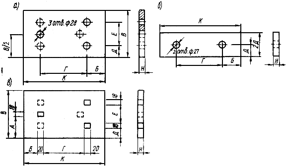
The rails are joined together, as a rule, by standard double-headed rail pads (Fig. 6). It is allowed to use apron pads for joining rails P38 and P43 (Fig. 7).
Fig.6. Double head pads
a - for rails P38, P43 and P50; b - for P65 rails
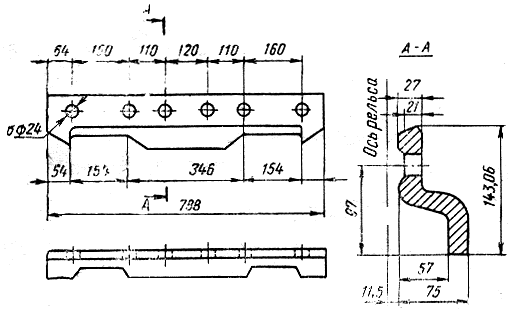
Fig.7. Apron cover for rails P38 and P43
To fasten rail joints with standard railway pads, bolts with a hexagonal reduced head and a guide support, hexagonal nuts of normal accuracy and spring washers are used.
To fasten rail joints with apron linings, track bolts and nuts made of low-carbon steel are used. Tower cranes of types KB and MSK have unified running trolleys equipped with rail anti-theft grips of a vice type with jaws permanently inserted under the head of the rails, which cannot work on crane tracks where the rails are joined by standard railway linings.
To connect the rails on the tracks for these cranes, special, non-standard butt clamps such as NIIMosstroy, VNIIStroydormash (Fig. 8-12) or other structures manufactured by construction organizations and not manufacturing plants are used.
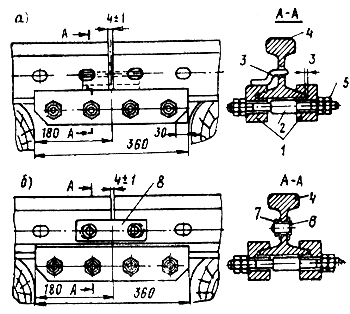
Fig.8. Butt joint of P43 rail with anti-theft pads
a - with a welded anti-theft fork; b - with anti-theft plates; 1 - left and right pads; 2 - hairpin; 3 - anti-theft plug; 4 - rail; 5 - nut; 6 - connecting finger; 7-washer; 8- anti-theft plate
Rice. 9. Details of butt clamps
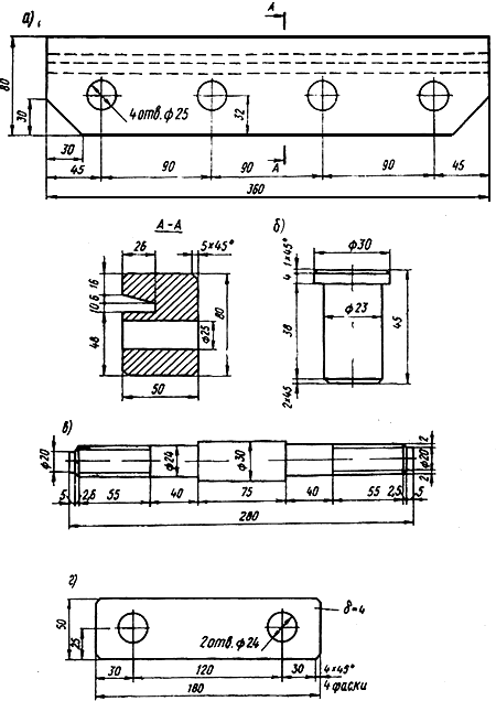
Fig. 10. Details of butt clamps temporarily permitted for use
a - overlay; b - connecting finger; c - hairpin; g - anti-theft plate
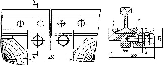
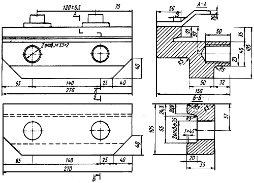
Fig. 11. Butt clamp
1 - base; 2 - clamp; 3 - hairpin; 4 - nut; 5 - spring washer
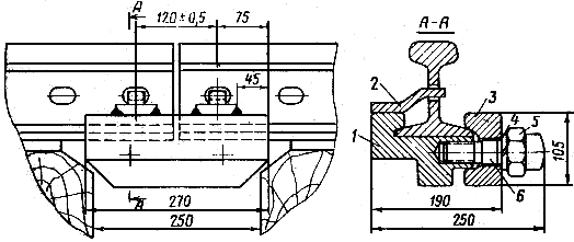
Fig. 12. Upgraded butt clamp
1 - clamp base; 2 - emphasis; 3 - clamp; 4 - washer; 5 - nut; 6 - hairpin
Since non-standard linings have their own dimensions for each type of rail, operating organizations with a diverse fleet of tower cranes have to produce several options for clamps, different in width, height and depth of the groove. Such overlays are complex and labor-intensive to manufacture, expensive, and most importantly, do not ensure reliable operation of the rail joint, which sometimes leads to an accident due to violation of the rail joint. In addition, the joint parts in the clamp linings are weakened; the shift of the rails in relation to the supporting elements when the wheels collide with the joint occurs in the longitudinal plane, therefore, the gap between the rails increases (rail hijacking); the shift of the rail heads relative to each other is carried out in the vertical and horizontal planes; there are cases of destruction (puncture) of the rail base; the junction of the elements with the rail is fragile; the design of reinforced concrete supporting elements is more complicated.
It is allowed to temporarily use clamp linings on the tracks for tower cranes of the KB series until the vice grips are replaced on their running trolleys with more advanced ones that allow the use of standard railway linings. For these purposes, it is recommended to replace vice grips with semi-automatic rail structures of TsNIIOMTP (Appendix 1), which enable cranes of the KB and MSK types to work on tracks where the rails are coupled with standard railway pads and at the same time are in constant engagement with the rail head.
Currently, some construction organizations, instead of vice-type anti-theft grips, use folding screw grips, similar to grips on BKSM type cranes, installed at the ends of the undercarriage, and the rails are joined with standard railway pads. Other organizations use the vice grips open so that they pass through the double-headed rail pads standard type, or remove them without replacing them with anything, so that it is possible to join the rails with standard railway pads.
However, none of these types of grippers are widely used for the following reasons:
1. With local subsidence of the track, as with dynamic overload of cranes of types KB and MSK, the running trolleys of the crane are slightly torn off the rail (by the amount of the flange of the running wheel) and the flange disengages with the rail head, at this moment the trolley can turn around in relation to vertical axis or one of the weather vanes (on cranes of types MSK-10-12 and MSK-7-25, where not all weather vanes are secured by rods to the running frame). Such a turn leads to the derailment of the crane and, consequently, to its fall.
2. When the vice grips are removed and there are no other grips, the crane is not protected from being blown away by the wind, which is a violation of the “Rules for the design and safe operation of load-lifting cranes” of Gosgortekhnadzor.
3. Vise grips, operating with a constant grip under the rail head, protect the crane from tipping over during overloads and track subsidence, since at the moment of instability, the grip through the rail head brings the crane runway into operation as additional ballast. When replacing vise grips with folding ones, this advantage is lost.
To more evenly distribute the pressure from the rail onto the supporting element (sleeper, bed, block, slab), flat metal pads should be installed under the rails. The linings also serve to protect the sleepers from premature wear and strengthen the fastening of the rails to the supporting elements. It is allowed to install rails on sleepers without pads when constructing tracks for cranes whose pressure on the running wheel does not exceed 150 kN.
The designs of fastening elements used to connect rails with supporting elements are very diverse and depend on the type of supporting elements. The most common for fastening rails to wooden sleepers received track screws with clamps (Fig. 13, a and b) and railway crutches (Fig. 13, c). These same elements are often used to attach rails to reinforced concrete support elements with wooden dowels. The pads used to fasten the rails to the sleepers with track screws and crutches are shown in Fig. 14. Technical characteristics of the linings are given in tables 6 and 7.
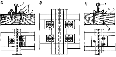
Fig. 13. Fastening rails to sleepers.
a - travel screws on a solid lining; b - the same, on two separate pads, c - with crutches, 1 - rail, 2 - track screw; 3 - clamp; 4 - lining; 5 - sleeper; 6 - crutch
Rice. 14. Pads for fastening the rail to the sleepers
a and b - travel screws; c- crutches
Table 6. Technical characteristics of pads for fastening the rail to sleepers with track screws (GOST 809-71)
|
Rail type |
Dimensions of pads (according to Fig. 14, a and b), mm | ||||||||
|
solid |
bandpass |
||||||||
Table 7. Technical characteristics of pads for fastening the rail to sleepers with crutches
|
Rail type |
Dimensions of pads (according to Fig. 14, c), mm |
Pad weight, kg |
|||||||
It is possible to make a lining with additional holes for fastening two types of rails, as shown by the dotted line in Fig. 14, a and c.
The specified linings can be replaced with linings made of strip steel (Fig. 14, b). Two such pads are installed on each sleeper.
When using railway chocks, it is recommended to pre-cut the sleepers to ensure the vertical position of the rail axis (Fig. 15). According to SN 78-73, it is allowed to use railway chocks without weaving in sleepers or preliminary removing the slope.
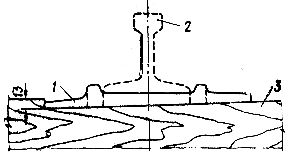
Fig. 15. Installation of railway lining
1 - railway lining; 2 - rail; 3 - half sleeper
The rails are secured to the supporting elements using various clamps, brackets, bolts, embedded parts, welding, spring or other special fasteners.
The clamps are shown in Fig. 16, and their technical characteristics are given in Table 8.
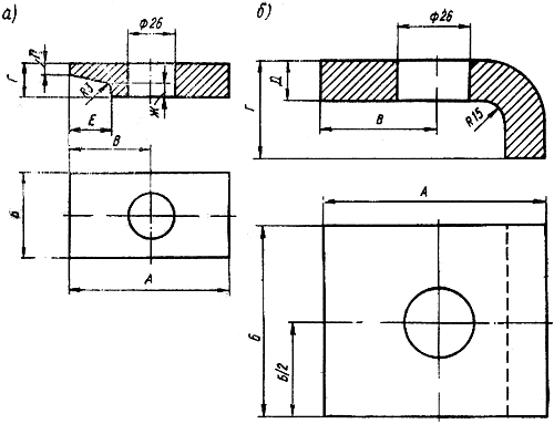
Fig. 16 Clamps for fastening the rail to the sleepers with screws
a - ordinary; b - lightweight
Table 8 Technical characteristics of clamps for fastening rails to sleepers with track screws
|
Rail type |
Clamp dimensions (according to Fig. 16), mm |
Clamping weight, kg |
|||||
Note. The numerator gives the dimensions of the clamp performed according to Fig. 16, a, the denominator - according to Fig. 16, b
No less common are embedded bolts and other fastenings of rails with reinforced concrete, metal and mixed (wood-metal, wood-reinforced concrete) supporting elements.
When fastening the rails to the supporting elements using embedded bolts and screws, the vibration of the pads is reduced to a minimum, reliable pressing of the pads to the rails is ensured, and it becomes possible to adjust the position of the rails in height up to 15 mm by laying a set of steel plates of variable thickness between the base of the rail and the pad.
Ballast layer designed to ensure the stability of rails and supporting elements under the influence of vertical and horizontal loads (including transverse), their uniform distribution and elastic transmission through the supporting elements to the roadbed.
The following materials are used as a ballast layer when constructing rail tracks - sand, crushed stone, metallurgical slag, sorted and quarry gravel. (Tables 9 and 10).
Table 9. Particle size distribution of ballast materials and standards of impurities
|
Particle sizes | |||||||||
|
Name of material |
Type of material - la (by particle size) |
Size normal particles size, mm |
linen size, less |
small, mm |
less than normal |
more normal |
Note |
||
|
natural stone |
Large (normal) |
Crushed stone must be clean, free from dirt and debris. The allowed content (by weight) of dust particles less than 0.1 mm in size is not more than 2%. |
|||||||
|
career |
measuring up to 3 mm) |
The allowed content (by weight) of dust particles less than 0.1 mm in size is no more than 8%, including clay particles less than 0.005 mm in size no more than 1.5% |
|||||||
|
sorted- |
Allowed content (by weight) of particles less than 0.1 mm in size is no more than 2% |
||||||||
|
Large and medium |
No more than 50 |
No more than 50 |
The allowed content (by weight) of particles less than 0.1 mm in size is no more than 10%. including clay 3% |
||||||
|
Granulated slag metallurgical |
Allowed content (by weight!) of particles less than 0.1 mm in size is no more than 4% |
||||||||
Table 10. Physical and mechanical properties of ballast materials
|
Mechanical strength | |||||
|
Name of material |
impact resistance on a pile driver PM, Pa |
material wear, by weight, % |
Water absorption value after 48 hours, % |
Frost resistance |
|
|
in drum N 1 type Los Angeles |
in drum No. 2 of the Deval type | ||||
|
Crushed stone from natural rocks: | |||||
|
Should not be destroyed. after 25 times freezing to a temperature of -15°C and after thawing |
|||||
|
medium hard | |||||
|
career | |||||
|
assorted |
Should not collapse after 25 times freezing to a temperature of -15°C and after thawing |
||||
Notes: 1. The mechanical strength test of ballast materials is carried out on one of the drums. 1. Frost resistance tests are carried out only in cases where water absorption exceeds the norm.
It is not allowed to use granulated slag for the ballast layer if it has not passed the test for lime and iron decomposition. The slag basicity modulus M must be less than unity.
If a sand-gravel or sand-crushed stone mixture in a 1:1 ratio is used for the ballast layer, you can use sand of a finer fraction than indicated in Table 9.
To determine the quality of ballast material, it is necessary to carry out control tests of samples for particle size distribution and ballast purity (percentage of impurities and small particles). Depending on the ballast material, such tests must be carried out using the methods specified in the technical specifications.
With proper interaction of the base of the rail track with the ballast layer, its density should be equal to the density of the main subgrade area. The ballast layer, laid on a subgrade made of soil with non-standardized density (rocky soil, etc.), is compacted to the standards given in Table 2. The density of the ballast layer is checked using the same methods and instruments as the density of the earthen base of the track.
To ensure a given density, ballast materials are laid in layers no more than 200 mm thick, which are compacted evenly (as they are laid). In summer, each layer of sand is additionally compacted with a spray of water.
The ballast layer is usually laid so that a prism is formed in the cross section. The dimensions of the ballast prism depend on the design parameters (see Fig. 3) and on the technical characteristics of the crane given in Tables 11 and 12.
Table 11. Dimensions of the ballast prism and the consumption rate of ballast materials for the installation of a rail track link on wooden and wood-metal sleepers
|
Chassis |
Ballast layer height h, mm | |||||||||
|
travel the first wheel |
completely of the prism at the top (Fig. 3), mm |
with a solid prism |
with separate prism |
|||||||
|
Crane type |
tele base |
from sand and granules metal chemical slag |
from crushed stone and gravel |
from sand and granules metal chemical slag |
from crushed stone and gravel |
from sand and granules metal chemical slag |
from crushed stone and gravel |
|||
|
MBSTC-80/100 | ||||||||||
|
BCSM-3-5-5B | ||||||||||
|
MSK-8/20 (MSK-7.5/20) | ||||||||||
|
KB-100.0 lattice, KB-00.0 | ||||||||||
|
KB-100.1 tubular | ||||||||||
|
M3-5-5, M3-5-5A | ||||||||||
|
SBK-1 (BCSM-3, T-228) | ||||||||||
|
SBK and TsEKB TsNIIOMTP | ||||||||||
|
KB-306 (S-98) | ||||||||||
|
MSK-10-20 (MSK-7-25) | ||||||||||
|
KB-404 (KS-250) | ||||||||||
|
BCSM-5-10 (T-223) | ||||||||||
Note. When installing separate prisms, their width is assumed to be 1750 mm.
Table 12. Size of the ballast prism and consumption rates of ballast materials for the installation of one track link on reinforced concrete beams and slabs
|
Chassis |
Ballast layer height, mm |
Consumption of ballast materials per link 12500 mm long, m |
||||||
|
Crane type |
pressure on the running wheel, kN |
number of wheels |
trolley base, mm |
Width of a solid prism at the top D (Fig. 3), mm |
from sand granulated metallurgical slag |
from crushed stone and gravel |
with a solid prism of sand, crushed stone and granulated bathroom metallurgist- chemical slag |
when separating a prism made of sand, crushed stone and granules metallurized organic slag |
|
MBSTC-80/100 | ||||||||
|
BCSM-3-5-5B | ||||||||
|
MSK-8/20 (MSK-7.5/20) | ||||||||
|
KB-100.0 lattice, | ||||||||
|
KB-100.1 tubular | ||||||||
|
M-3-5-5, M-3-5-5A | ||||||||
|
SBK-1 (BCSM-3, T-228) | ||||||||
|
SBC and TsECB | ||||||||
|
TsNIIOMTP | ||||||||
|
KB-306 (S-981) | ||||||||
|
MSK-10-20 (MSK-7-25) | ||||||||
|
KB-404 (KS-250) | ||||||||
|
BCSM-5-10 (T-223) | ||||||||
Notes: 1. When installing separate prisms, their width is taken to be 1200 mm, the height of the ballast layer of sand, granulated slag, gravel and crushed stone is not less than 100.
2. Ballast consumption is given taking into account the partial layout of the base.
To maintain the specified shape and dimensions of the track, it is not allowed to lay a ballast prism on an unprepared subgrade. When installing a ballast prism, it is necessary to observe certain slopes of its sides: for sand and granulated slag 1:2-1:3; for crushed stone and gravel 1:1.5.
When constructing a track on bulk soil in cramped conditions and in areas with strong winds, the sides of the ballast prism are protected (see Fig. 3, b).
The electronic text of the document has been prepared
JSC "Kodeks" and verified by:
All-Russian Public Fund
"CONSTRUCTION QUALITY CENTER"
St. Petersburg
KranStal LLC specializes in the design, installation, and production of crane tracks (crane tracks) and trestles for them. We solve problems of any level of complexity - design, inspection, installation, repair of overhead and ground crane tracks in the case of installation of new lifting and transport equipment on an unequipped production site or building, refurbishment of an existing production site, as well as if existing equipment is transferred to another production site . Our specialists go to the site of the intended installation of the PTM and carry out a range of works aimed at improving and increasing productivity.
Crane structures for overhead cranes consist of:
Crane beams or trusses that support vertical crane loads;
. brake structures that absorb transverse horizontal impacts from cranes;
. connections that ensure rigidity and immutability of crane structures;
. support units that transmit crane impacts to the columns;
. crane rail with fastenings;
. dead-end stops.
Load patterns and composition of crane structures.
The rail support track of an overhead crane consists of main and auxiliary elements. The main elements of the track are rails and crane beams. TO auxiliary elements include the under-rail bed, parts for fastening rails to crane beams and beams to columns, as well as end stops and switching rulers.
For the movement of load-lifting cranes and their cargo trolleys equipped with running wheels with a cylindrical rim, steel rails with convex and flat heads are used, and for wheels with a conical rim - only with convex heads. Railway rails are used as bullnose rails. broad gauge type P and special crane rails like KR according to GOST 4121 - 76, and with flat heads - steel bars with a square or rectangular profile. Steel crane rails of the KR type have a wider base (supporting part), due to which the load from the crane running wheels is distributed more evenly over the upper belt of the crane beam. In addition, they absorb horizontal lateral loads well and are more suitable for the operating conditions of load-lifting cranes. Therefore, for cranes of the 6K-8K operating mode group, only KR type rails are used. Example symbol rail type KR with a nominal head width of 100 mm: Rail KR100 GOST 4121 - 76. Recommendations for the selection of crane rails depending on the load capacity of the crane and the load on the running wheel.
Crane rails of the KR type are laid on special bases or attached to crane beams in two ways:
Fixed mount;
Movable mount;
Fixed mount The KR rail is carried out by welding and is most typical for cranes with light duty operation.
But still, the most recommended way is movable fastening rails type KR, because it provides convenient and comparatively simple replacement worn rails and allows for high-quality track alignment.
Crane rails of the KR type are often secured to the crane beam with paired ties with a diameter of 22-25 mm, and special ones - with side plates. Paired strands and side linings are installed in increments of 600-700 mm. Rails of rectangular and square profiles can be attached to beams using strips inserted into the grooves of the beam.
Types of crane racks:
1. free-standing crane rack
2. built-in overpass
3. crane trestle for support crane
4. crane trestle for overhead crane
5. free-standing monorail track
6. suspended monorail track (straight and with a turn)
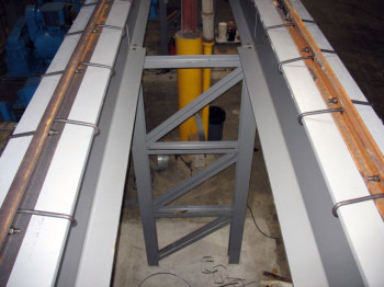
Freestanding crane trestle
The columns of a free-standing overpass are installed on their own foundations. Crane beams with a crane rail are installed on the column heads. In the transverse direction, the stability of the overpass is ensured by the developed foundation on which the column cross-beams are fixed; in the longitudinal direction, stability is ensured by tie trusses (one in each track branch).
L
Le
Lzd
Sh
U.G.R.
U.S.C.
Built-in crane trestle
Columns of the built-in overpass rest on support flanges installed on the workshop floor. The top of the columns is secured to the trusses (beams). Crane beams with a crane rail are installed on the column consoles. In the transverse direction, the stability of the overpass is ensured by transferring the load to the building floor; in the longitudinal direction, stability is ensured by tie trusses (one in each track branch).
L- crane track span - distance (in plan) between the rail axes
Le- overpass span - distance (in plan) between the axes of the overpass columns (across the rails)
Lzd- span of a building, workshop - distance (in plan) between the axes of the columns of a building, workshop (across the rails)
Sh- column spacing - distance (in plan) between the axes of the columns (along the rails)
U.G.R.- rail head level - distance (in height) between the floor, ground, zero level and rolling surface of the crane rail
U.S.C.- level of the building structure - the distance (in height) between the floor, ground, zero level and the lowest point of the truss, beam.
Crane trestle for support crane
In the crane trestle of the crane support for the crane track, workshop columns are used. Crane beams with a crane rail are installed on the column consoles. Longitudinal and transverse loads are carried by the workshop columns.
L- crane track span - distance (in plan) between the rail axes
Le- overpass span - distance (in plan) between the axes of the overpass columns (across the rails)
Lzd- span of a building, workshop - distance (in plan) between the axes of the columns of a building, workshop (across the rails)
Sh- column spacing - distance (in plan) between the axes of the columns (along the rails)
U.G.R.- rail head level - distance (in height) between the floor, ground, zero level and rolling surface of the crane rail
U.S.C.- level of the building structure - the distance (in height) between the floor, ground, zero level and the lowest point of the truss, beam.
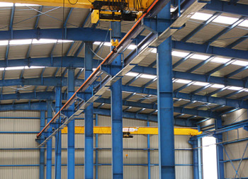
Crane trestle for overhead crane
In the crane trestle of an overhead crane, I-beams are used as a crane track (24M, 30M, 36M, 45M), which are suspended from roof trusses(beams). Longitudinal and transverse loads are transmitted to the floor through braces.
L- crane track span - distance (in plan) between the rail axes
Le- overpass span - distance (in plan) between the axes of the overpass columns (across the rails)
Lzd- span of a building, workshop - distance (in plan) between the axes of the columns of a building, workshop (across the rails)
Sh- column spacing - distance (in plan) between the axes of the columns (along the rails)
U.G.R.- rail head level - distance (in height) between the floor, ground, zero level and rolling surface of the crane rail
U.S.C.- level of the building structure - the distance (in height) between the floor, ground, zero level and the lowest point of the truss, beam.
Freestanding monorail track
Suspended monorail track (straight and with a turn)
I-beams (18M, 24M, 30M, 36M, 45M) are used as a monorail track, suspended from trusses (beams). Longitudinal and transverse loads are transmitted to the floor through braces.
straight section
area with a 180 degree turn
Rail track An overhead crane consists of main and auxiliary elements.
Main elements The paths are rails and crane beams.
TO auxiliary elements include the under-rail bed, parts for fastening rails to crane beams and beams to columns (floors) of a building structure, as well as end stops and deflection rulers.
For crane tracks of overhead single-girder cranes with a low working load, railway rails of the P18, P24 type are used. Double-girder overhead cranes with a lifting capacity of 10-30 tons of light and medium operating modes are operated on tracks made of type P38 rails, with a lifting capacity of 10 tons - type P43, etc. It should be noted that P43 type rails are produced specifically for industrial transport. For cranes with greater lifting capacity, factories produce railway rails of the P50 and P65 types (Fig. 8, a).
Currently, the domestic industry produces steel crane rails with a special profile of the KR type, corresponding to the operating conditions of overhead, gantry and jib cranes (Fig. 8, b).
Special crane rails of the KR type have a wider base, due to which the load from the running wheels of the crane is distributed over the upper belt of the crane beam more evenly. In some cases, hot-rolled square steel is used as rails with flat heads (Fig. 8, c).
Rice. 8. Rail profiles of supporting crane tracks:
a - railway type P,
b - crane type KR,
c - square profile steel
Depending on the crane's lifting capacity, the type of support rail is selected.
The rails of crane tracks and cargo trolleys are secured in such a way as to prevent their lateral and longitudinal displacement during movement and operation of the lifting machine. The crane rails of the support track are attached to the crane beams of the building structure (workshop, overpass), which, depending on the loads, operating mode of the crane and the type of building structure, are made from profiled rolled steel, welded from sheet metal or from precast reinforced concrete. The rails of cargo crane trolleys are attached directly to the metal structure of the crane bridge.
Rice. 9. Fastening rails to crane beams:
a - welded staples,
b - clamping pads,
c - spring bars,
g - hooks with adjustable nuts,
d - spring brackets;
1 - rail, 2 - bracket, 3 - cover plate, 4 - bolt with nut,
5 - spring bar, 6 - hook, 7 - nut, 8 - spring bracket,
9 - stud with nut, 10 - rubber gasket
Exist various ways fastening rails to crane beams (Fig. 9). Preference was given to prefabricated fastenings, which provide the ability to perform horizontal straightening of the track and simple repairs with the replacement of rejected sections of the rail. To adjust the fasteners when straightening the path, in clamping bars make oval holes or drill them in place. For overhead cranes with manually driven mechanisms and cranes with a lifting capacity of up to 30 tons in light operating mode, the Rules allow the rails to be fastened to the crane beams by welding.
As suspended crane tracks for overhead cranes, special rails are used, attached from below to the floor elements building structures(trusses, rafter beams) using hangers or mounting tables. As monorails for mobile hoists and hoists, special double-headed, T-type or P5 type rails are used. For suspended crane beams with a lifting capacity of up to 1-2 tons with a span of less than 6 m, I-beams No. 12-30 (GOST 8239-72) made of hot-rolled steel grade VSt3ps are used as supporting rails. For machines with a larger load capacity (up to 5 tons), special-section I-beams No. 24 M-45 M (GOST 19425-74) are used.
The fastening of overhead crane tracks is carried out using hangers welded to the metal structures of the steel floor trusses.
To stop lifting cranes on rails, in order to avoid emergency situation associated with its derailment from the rail track (due to the failure of the limit switch), mechanical safety devices. These devices are dead stops . They are used on rail tracks of tower, gantry, portal and overhead cranes. The exception is rail railways, along which the rolling stock moves, and they have exit on the tracks common use or on the path of industrial enterprises.
Types of stops and buffers:
· Drums (the crane stops due to the absorption of kinetic energy by rubber, spring, pneumatic hydraulic cylinders, or wooden elements installed on dead-end stops and buffer elements of cranes),
· Unstressed (stopping due to energy absorption by overcoming the roller coaster of the dead-end stop),
· Combined type.
Dead-end stops are installed in strict accordance with the crane runway design or crane operating manual. They are tested by the manufacturer before installation. The passport for the set of dead-end stops must contain a corresponding mark. After installation, the consumer checks the integrity and completeness of the products, correct installation, and also checks their functionality. These results are recorded in the acts of commissioning of the crane rail track.
In turn, the bridge moves on rails, and the cargo trolley moves along the bridge. Overhead cranes are single-girder and double-girder, have a manual or electric drive; as for the cabin, it can be either self-controlled or controlled using special devices from afar.
Single-girder and double-girder cranes can be either support or suspended. The support crane moves on special rails, and the suspended crane moves on I-beams.
Features of fastening to crane tracks
There are overhead cranes: magnetic, hook, grab, and also with electric lifting magnet.
There are overhead cranes: magnetic, hook, grab, and also with electric lifting magnet. The type of overhead crane depends on what kind of load they will be lifting. There may be overhead cranes with special devices for lifting loads (for example, pliers, paws, etc.).
Overhead cranes have a suspension that can be flexible or rigid. The flexible suspension consists of ropes. With a rigid suspension, everything is different; cranes used in the metallurgical industry are produced with it. In metallurgical cranes, the most important working part is connected to the cart using a shaft and moves along special columns in a vertical position.
They have an I-beam that is attached to cross beams which have running wheels. Double girder overhead cranes have two parallel beams attached to common beams. Here the cargo trolley moves on rails. Under enormous loads, the crane bridge is strengthened using box beams or lattice trusses.
Overhead cranes can be driven using electric motors, about which you can learn more by reading. They are located on the front gallery of the crane bridge. The movement mechanisms are controlled by a central or separate drive.
Described above, but there are overhead cranes for special purposes. Cranes that serve for pouring cast iron or casting steel are foundry cranes. Taps designed for servicing heating wells are tick-type and so on. Almost all cranes have special platforms that are located outside the cabin and with the help of which you can examine all the crane mechanisms and electrical equipment.
Features of the use of different types of crane tracks
Rail tracks of overhead cranes consist of main and additional devices. The main devices include crane rails and beams.
Rail tracks of overhead cranes consist of main and additional devices. The main devices include crane rails and beams. Additional devices include under-rail beds, various fasteners, deflecting rulers and end stops.
For various types overhead cranes use different rail tracks. So, for single-girder overhead cranes, ordinary rails are used, like for trains. For double-girder overhead cranes, more powerful rails are used. Such rails are produced specifically for industrial transport.
The rails of the crane tracks are secured so that no displacement can occur during the movement and operation of lifting machines. These rails are attached to special beams, which are made of steel, depending on the loads.
The most common and convenient fastenings– collapsible. There are also fastenings using welding, but this type of fastening is inconvenient. It is used for cranes with low lifting capacity and for overhead cranes with a manual drive mechanism.
When working with it, you must remember that a special area must be equipped for parking the crane. The crane runway must comply with the track dimensions, landing, energy saving rules, grounding and other standards.
Repair of crane tracks depends on the type of tracks. As stated above, there is a ground and an above-ground crane track.
The rails to the beams, as noted above, are attached using fasteners. There are several ways of such fastening.
Repair of ground crane tracks includes, first of all, eliminating the difference in height on the tracks. Determine the degree of wear, if it is necessary to replace the rails on the crane tracks, as well as replace the main and additional (fastening) elements. Electrical equipment repair. After eliminating the deficiencies, the final leveling of the crane runways is carried out. It is necessary to determine the quality of the repair performed.
Repair of overhead crane tracks includes inspection of fasteners, beams, and identification of problems. Then the fasteners and rails are replaced. Repair of guides, joints. As well as repair of electrical equipment and cables, that is, items designed to conduct current.
And yet it is necessary to remember: in order to prevent breakdown or failure of any equipment, you always need to monitor the condition of the crane runway equipment.