Section: Machines and tools
The goal of our work will be to make a cutting machine with our own hands. There is no need to describe how useful and necessary such equipment is in the work of any craftsman. and just on the farm.
We will start manufacturing from the frame-frame, its dimensions 700*1000*900 mm.
A 25*25 mm corner would be an excellent material for the frame; we cut the blanks with a grinder and weld them. We weld channel No. 10 to the upper plane of the frame at a distance of 70 mm from the edge, to which, in turn, two vertical racks from a square 40*40 mm.
The racks are connected by a #216 12 mm shaft with a sleeve fitted (to avoid end movements of the disk, the shaft-bushing connection is made with a sliding fit with minimal clearance). A rocker arm from the same channel No. 10 measuring 800 mm is welded to this bushing, and in such a way that the arms are in a ratio of 1:3.
The electric motor is mounted on the smaller part of the rocker, the working shaft is mounted on the larger part, and the transmission of motion will be carried out using a belt drive.
Now about the electric motor. Preference should be given to asynchronous motors, as they are more reliable and durable. Practice shows that for normal operation with a cutting disc #216 400 mm, a “three-thousander” with a power of 2.2 kW, powered from a three-phase network, is ideal. One and a half thousand will do, but gear ratio The belt drive must be selected so that the shaft has about 6000 rpm. In case of power supply single-phase network. The engine power should be increased by 30% and operating and starting capacitors should be used.
We order the working shaft with supports, flanges for the disc and a pulley for the “A” type belt to a turner, and the flange protrusion should be #216 32 mm. In this case, it will be possible to install both a cutting disc and a saw blade for wood on the machine. Both the motor and the shaft are secured to the shaft using M10 bolts and nuts.
The stroke of the rocker arm is limited by the chain, and springs are installed on the engine side to facilitate return (for example, from a sports expander). Fastening chains and springs using bolts.
The table is made from planed boards 40-50 mm thick and covered with plywood or USB to smooth out small irregularities.
And further important point . When installing the shaft, you should install the saw blade and carefully check the perpendicularity of the planes of the blade and the table. If necessary, the position of the shaft must be leveled by using shims on the shaft bearing supports.
And finally, the last thing. DO NOT FORGET to provide disk protection.
The disk runs on high speed, the ejection of abrasive and metal particles is possible, and in the case of using a saw blade with carbide tips, the ejection of the latter. Disk protection is required!
What is needed for a cutting machine
Watch the video: Cutting machine for metal. Do it yourself. (Homemade cutting machine for metal.)

Download the image (preview) by selecting quality
Dear friends!
The source of all video content, including that played on the pages of the androidmafia.ru resource, is a third-party video resource, namely the public video hosting YouTube.com, which provides open access to its video content (using open and publicly available technology video API3 youtube.com)!
Copyright issues
If you own the copyright to a video that was uploaded to YouTube.com without your consent, please go to the video's page on YouTube.com. click on the link under the player More - Complain - Violation of my rights and in the drop-down menu, select what exactly is being violated and click the Send button. Copyright section on YouTube.com
Inappropriate Content
To report an inappropriate video, go to YouTube, click on the link below the player More - Complain and select in Report violation what exactly you are not happy with in this video. Read more about our rules in our Terms of Use.
Go to this video page
Do-it-yourself cutting machine from an angle grinder - convenience and practicality!
The grinder is a very useful and versatile tool. With its help you can cut metal, stone, tiles and, of course, grind surfaces, but sometimes it is much easier and more accurate to perform these works stationary machine. Luckily, you can make your own grinder cutter!
Homemade machine for an angle grinder - pros and cons
If you have to hold an angle grinder in your hands quite often, you have probably already experienced its disadvantages. The weaknesses of the tool stem from its main advantage - mobility. Firstly, it is not always possible to secure parts during cutting, and their slightest vibration can lead to destruction abrasive disc, which in turn is fraught with serious injuries.
Secondly, with a mobile version of the tool it is quite difficult to control the precise perpendicularity of the cut, take into account the thickness of the disk in relation to the mark and the material being cut, and even hold it if necessary. Thirdly, it is quite difficult with a tool to cut several parts of the same size, especially when it comes to twigs and small pipes - after cutting you also have to trim the parts.
And, of course, keeping both hands busy and extremely tiring concentration when working, since an angle grinder is one of the most dangerous tools. Just look at the kickback – the sudden kickback of the tool when the rotating abrasive disc gets jammed in the workpiece. The danger of a kickback lies not so much in the throwing of the tool, but in the concomitant destruction of the circle. At such high speeds, abrasive fragments can seriously injure the operator.
The kickback occurs especially often when a cut is completed, when only a small bridge connects the parts. In this case, it is recommended to stop the tool without cutting the workpiece to the end, remove the circle and cut the part with reverse side. A cutting machine that you can construct with your own hands from enough available materials, is able to solve all of the above problems and provide additional security.
Making a cutting machine is a simple option
Find finished machine on store shelves that at first glance satisfies your needs is a fairly simple task. But it is unlikely that there will be a design that fully meets all the requirements, because everyone’s requirements are different! In such cases, owners of machine tools try to improve or remodel them, but are faced with very serious obstacles - either the manufacturers made the machine from alloys that are very difficult to work with by welding, or they did not take into account the little things that you need specifically - for example, an accurate ruler or a more elastic spring. Remaking someone else's is much more difficult than making your own!
Simplest homemade machine for a small grinder you can do it yourself at a minimum cost and in just a few hours! The finished structure will be a long metal pipe that serves as both a frame and a handle. Closer to one end, a transverse metal strip with two holes for fastening the grinder is welded.
On the same side, the pipe is attached to one side of a small piece of angle on a movable shaft, while the other side of the angle itself is attached either to the work table, or simply to the floor in the garage! It is important to fix a spring on the opposite side of the mount, which will allow the entire structure to return to its original position. That's all - the machine is ready, you just need to secure the angle grinder correctly. Of course, this option is for the most simple work, for more precise and complex procedures it is necessary to make a more complex structure.
Do-it-yourself cutting machine from an angle grinder - for precision work!
To make a cutting machine you will need following materials and tools: steel angle, profile pipe, metal sheet for the platform (or a lighter chipboard version), welding machine, channel, drill, shaft, several identical bearings, a small diameter pipe, a spring, as well as a relay and pedal. Welding, if you think about it, can be replaced with strong bolts - that's why you need a drill. By the way, this option will also allow you to disassemble the machine if necessary.
How to make a cutting machine from a grinder with your own hands - step-by-step diagram
Step 1: Parts and drawing
The manufacture of the machine should begin with cutting parts onto the frame. To prevent damage to expensive material, carefully study the numerous drawings that can be found on the Internet or follow the models on the shelves. In the latter case, draw up a drawing yourself; you don’t need any special skills for this - the main thing is to present the finished structure and its proportions on paper. Each grinder needs its own drawing, because tools from different manufacturers can differ radically - in some places you can remove the handle, in others you’ll have to come up with a stand for the entire grinder! Plus, under different sizes The disk needs a different frame.
Step 2: Frame
The simplest frame consists of two frames on a common axis. The lower frame should be fixed to a platform - metal or chipboard. If the grinder is large, it is better to use metal. The upper frame, to which the angle grinder is screwed, should rotate vertically relative to the lower one, like a pendulum. A spring is needed to fix the original position. A fastening is welded to the lower frame, which consists of a clamping angle and a movable clamp.
Step 3: Ruler
It is very important to provide measuring parts in the machine, thanks to which you can cut workpieces with an accuracy of up to 1 mm. In this case, a movable ruler with a limiter welded to the tube is best suited. Having set the exact size using it and secured with an end screw, you can get to work!
Step 4: Electronics
For ease of operation, provide in the design a start pedal or button with switching through a low-voltage 12 V relay. Through it, voltage will be supplied to the angle grinder. With the help of such a simple design, we free up our hands, achieve an accurate, even cut without using a vice, and also save time on accurate measurements. This tool will replace a cutting saw for metal, and if necessary, you can always return the angle grinder to its mobile state.
Do-it-yourself grinder machine - safety first!
When working with an angle grinder, stationary or manual, you should always remember safety. In the case of a stationary option, you need to take into account the direction of the tool and the position of the protective casing - it is important that the casing completely hides the area in which the operator is located. If you have a machine, you will probably have a desire to use the tool for other purposes than for its intended purpose - for example, attach a saw blade for wood to an angle grinder, which is absolutely forbidden to do!
Wood is a heterogeneous material; it may contain knots or even nails. The rotation speed of the grinder significantly exceeds the set speed of a standard sawmill, which will very quickly lead to saw blade into disrepair.
But, in addition, unlike abrasive and grinding discs, saw blades have sharp teeth that pose a high danger. Risking your health for a quick cut is simply unreasonable. After installing the tool and the new disk, the operation of the grinder should be checked for at least 1 minute at idle speed - the circle should rotate completely freely, without excessive vibration, without touching the casing.
Leave the solution for 5-6 hours. Then the foam will separate and rise up, leaving liquid below. You need to carefully drain this liquid and spread it on the painting in several layers. After each layer the painting must dry completely. Then you can hang the picture and forget about it for half a year or a year. Then the painting should be washed with water. After this, you can safely coat the picture with varnish.
How to pour sugar into a glass: In order to pour sugar into a glass, you need to take a spoon, scoop it up, bring it to the cup and pour it out! ?
Do-it-yourself cutting machine from an angle grinder
DIY Milling Machine Drawings

Video on how to make your own metal cutting machine from an angle grinder
Click on Play to view
If you have to hold an angle grinder in your hands quite often, you have probably already experienced its disadvantages.
The weaknesses of the tool stem from its main advantage - mobility. Firstly, it is not always possible to secure parts during cutting, and the slightest vibration can lead to destruction of the abrasive disc, which in turn can lead to serious injuries.
Secondly, with a mobile version of the tool it is quite difficult to control the precise perpendicularity of the cut, take into account the thickness of the disk in relation to the mark and the material being cut, and even hold it if necessary.
Thirdly, it is quite difficult to use a tool to cut several parts of the same size. especially when it comes to twigs and small pipes - after cutting you also have to trim the parts.
And, of course, keeping both hands busy and extremely tiring concentration when working, since an angle grinder is one of the most dangerous tools.
Just look at the kickback – the sudden kickback of the tool when the rotating abrasive disc gets jammed in the workpiece. The danger of a kickback lies not so much in the throwing of the tool, but in the concomitant destruction of the circle. At such high speeds, abrasive fragments can seriously injure the operator.
The kickback occurs especially often when a cut is completed, when only a small bridge connects the parts.
In this case, it is recommended to stop the tool without cutting the workpiece to the end, remove the circle and cut the part from the reverse side. A cutting machine, which you can construct with your own hands from fairly accessible materials, can solve all of the problems listed above and provide additional safety.
2 Making a cutting machine - a simple option
Video on the topic
Finding a ready-made machine on store shelves that at first glance satisfies your needs is a fairly simple task.
But it is unlikely that there will be a design that fully meets all the requirements, because everyone’s requirements are different! In such cases, owners of machine tools try to improve or remake them, but are faced with very serious obstacles - either the manufacturers made the machine from alloys that are very difficult to work with by welding, or they did not take into account the little things that you need specifically - for example, an accurate ruler or a more elastic spring.
Remaking someone else's is much more difficult than making your own!
Grinder cutting machine

Having worked a lot with an angle grinder, I came to the conclusion that using this useful tool as efficiently as possible.
And this is what I came up with for this.
■ It is difficult to cut several parts of the same length from small pipes, rods, etc.
Trimming takes extra time, and each time you have to set a new mark.
■ It is necessary to constantly monitor the perpendicularity of the cutting, take into account the thickness of the disk in relation to the tube and mark, so that there is no error.
■ Vibration of the part during cutting leads to destruction of the disk in a matter of seconds.
By converting a hand tool into a stationary one, I eliminated the listed disadvantages.
The machine consists of two frames on a common axis (photo 1, 2).
The bottom one was rigidly fixed to a chipboard slab. (Fig. 1).
403 Forbidden
The upper one, with the angle grinder B screwed on, rotates vertically, like a pendulum, relative to the lower one (Fig. 2). The initial position of the tool is fixed by a tension spring.
To lower the cutting disc, I press the grinder handle down. When released, the cutting part returns back.
A dismountable fastening unit consisting of a movable clamp and a clamping angle is welded to the lower frame (photo 3).
Below is a movable measuring ruler with a limiter, welded to the tube.
Having locked the bar with an end screw, I set the size only once (with an accuracy of 1 mm), after which I cut the required number of absolutely identical parts of any size - right down to the rings.
I start the machine with a pedal with switching through a low-voltage relay (12 V), which with its powerful contacts supplies 220 V to B. Accordingly, neither the pedal nor the wire located on the ground, even if the insulation is damaged, pose a danger to humans.
I install, remove and fix B using a clamp that is used on top covers boxes for storing and transporting equipment (such as pads). The weight and dimensions of the machine allow it to be transported in a box of a passenger car.
Advantages of development
■ No need for a vice
■ Produces a very even cut
■ The pedal frees up your hands
DIY cutting machine
I plan to weld the frame of the stairs to the second floor and for maximum accuracy of cuts at an angle I need a cutting machine.
I started to take a closer look at them, but somehow the prices are not very childish, and there is little use for them on the farm in the future. At the insistence of those surveyed, the option of installing cutting wheel for metal in miter saw on the tree, was discarded.
I decided to pay attention to devices for grinders.
Watched different variants, the price varies from 300 to 600 thousand, but I didn’t like the longitudinal play in all of them.
Because of this play, there may be a deviation in the angle of up to 5 degrees. How lucky is that? After some thought, I decided to build such an adapter myself. It was a pity to waste 300 thousand on it.
What I needed:
* Bulgarian
* welding machine
* clamps
The materials used were second-hand iron, 3 bolts f 16 were purchased to fasten the angle grinder, and friends suggested a carriage from a bicycle.
As a result, personal time was spent - it is priceless
4800 for three bolts from speculators
10,000 for cutting wheels
Well, about a dozen electrodes and a couple of kilowatts of electricity.
After wallpapering: After gluing the walls in the room with wallpaper, you should not leave the room to ventilate, as the pasted wallpaper will begin to fall off or become covered.
To keep nails at hand: Sometimes we put nails or screws in our mouth, in our pocket, or simply hold them in our hand. It is much better to hang a magnet around your neck. They will be securely held on it in any quantity and your hands and mouth will be free

Homemade vulcanizer - production and use
If you have a punctured tire, the easiest option is to go to a tire shop. However, there are many who like to do everything themselves, and a tire service is not always nearby. Sometimes the costs associated with going to a tire shop (travel, time, the procedure itself) add up to a substantial amount, especially if you have to use this service often.
In general, for various reasons, for those who want to fix breakdowns at home, I offer several options making a homemade vulcanizer With minimal costs. Using a homemade vulcanizer, for example made from an iron, you can quickly and reliably repair cars, motorcycles and bicycle tubes, air mattress, heating pads, various pacifiers, inflatable toys, etc.
One of the most common options for a homemade vulcanizer is the option using an old iron.
The reason for this is new, more functional irons, and old (Soviet) irons in working condition (if you don’t have any left) will not be difficult to find from a neighbor. Here's a free basic vulcanizer part for you.
Below are a few designs. Which one to choose is up to you, the basic idea is the same, the difference is how to ensure a clamp connection at the place where the rubber product is vulcanized.

Raw rubber is soaked (for some time) in gasoline, the size is slightly less than the size of a patch.
The puncture site is treated with sandpaper (the size is generous) and wiped with gasoline. A patch is cut from tube rubber, the edges are rounded. The patch is also treated with sandpaper and then with gasoline. Next: put raw rubber on the hole, put a patch on it, clamp everything in our vulcanizer. You can place a piece of newspaper to prevent the rubber from sticking to the vulcanizer plate.
Wait until water comes into contact with the vulcanizer (15-20 minutes). Turn off the vulcanizer, wait a little, remove the vulcanizer, and let the rubber cool. They also check the temperature using granulated sugar: if its grains in contact with the hot vulcanizer begin to melt and turn yellow, then it’s time to turn off the vulcanizer.
If your thermostat is working, set it to 150 degrees. (approximately for ironing silk). The thermostat can be adjusted experimentally. If the smell of burnt rubber appears, this is a sign high temperature if the patch has not merged well (vulcanized) - a sign of insufficient temperature or short vulcanization time.
After one or two times everything becomes clear and vulcanization can be started :)
For more specific work, you will need a simple mold, which is made from two steel plates 6-8 mm thick and 40X60 mm in size. Four holes are drilled in the corners and an M4 thread is cut to tighten the halves with screws.
The inner edges of the plates are slightly ground down so that the edges do not cut into the rubber. In the case of a complex configuration of the parts being repaired, the plates are given the appropriate shape or additional holes and grooves are made.

Before starting work, thoroughly clean the area to be treated (the edges of the pasties are cut at an angle of 45°) and degrease with light gasoline (B-70).
Then a patch of the required size made of raw rubber is applied to the repaired area, placed in a mold and tightened tightly with screws. By placing it on a heated iron so that the entire plane of the lower half of the mold touches the heating surface, wait for 10-15 minutes.
During operation, make sure that the rubber does not touch the hot parts of the iron.
Grooves for gluing beads are drilled with the halves of the mold tightened, and the diameter of the drill should be equal to the diameter of the bead. You can drill several holes in one mold for different diameters of beads, but the distance between them must be no less than the thickness of the workpiece.
Otherwise, heating of the gluing area will be uneven and the quality of vulcanization will deteriorate.
Cleaning the gluing areas or trimming the ends of the bead is done immediately before work, and the raw rubber is applied in a thin layer - this will make the connection stronger.
Diagram of a vulcanizer with an integrated clamp

Vulcanizing iron: 1 - clamp bracket, 2 - boss, 3 - clamping screw, 4 - clamping heel, 5 - electric iron.
Cut a bracket from five-millimeter steel (see Fig.
figure), weld a cylindrical boss to it on top, and inside- a strip of metal 50 mm wide. The cross-section of the resulting clamp should have T-shape. Drill a hole along the axis of the boss and cut a thread in it for the clamping screw. Then bolt the iron body to the bottom of the clamp - and the vulcanizer is almost ready.
The simplest option vulcanization with iron- no modifications at all.

Raw rubber is applied to the cleaned area of the rupture, then paper and everything is pressed on top with an iron.
Some weight is placed on the iron. Vulcanization lasts 10-15 minutes, iron temperature 140-150 °C (thermostat in “silk” position). Since the exact temperature of the iron is unknown, care must be taken not to burn the rubber.
A burning rubber smell will indicate that the heat is too high.
Another option homemade vulcanizer made from an electric stove and a clamp
Based on the dimensions (diameter and height) of the ceramic base from a household electric stove with an open spiral, a welded heater body is made from iron 5 mm thick.
Four rod legs and a clamp are welded to its walls. You insert a ceramic element with a spiral into the body, on which, to prevent its contact with the metal, you need to put a gasket made of sheet asbestos.
From below, the electric heater is closed with an iron cover using two bolts.

Main details of a homemade vulcanizer:
1 - body; 2 - bottom cover; 3 - asbestos gasket; 4 — ceramic base with nichrome spiral; 5 - power cord.

A bimetallic thermostat from a regular iron, complete with a signal lamp and its resistance, is attached to the upper surface of the housing, near the clamp.
The electrical circuit of the vulcanizer is similar to the circuit of the iron. By monitoring the surface temperature of the vulcanizer plate with a mercury or other thermometer, the regulator is adjusted so that it turns off the heating element at a temperature of about 140-150°C.
DIY metal cutting machine
At the same time, the signal light goes out, which indicates that the vulcanizer is turned off. The heating time depends on the power of the heating coil.
And the last option is a traveling one that does not require electricity, which can be very useful in case of troubles along the way.
This homemade vulcanizer, made using a piston from a motorcycle or car engine, which requires only 40-50 grams of gasoline to use.

The vulcanizer is easy to manufacture and includes only a few parts:
1 - vulcanizer base
2 - bolts
3 - beam
4 - piston
5 - self-tapping screws
6 - nuts
7 — holes for self-tapping screws
8 — holes for bolts
Base 1 is made of wood, since wood does not interfere with good heating of the rubber.
Bolts 2 are inserted into the holes in the base and secured to the base using self-tapping screws 5, preventing them from turning in the hole in the base. . The bolts are made of a metal rod with a diameter of 12 mm. A washer is welded at one end of the rod, and an M12 thread is cut at the other.
A beam is placed on both bolts on the thread side, which, using nuts, presses the vulcanizer piston to the base.
The damaged chamber is placed between the base and the piston.
Materials and design can be changed - only the principle of operation is important.

To repair the camera, you need to find the damage, clean it, and wipe it with clean gasoline. Then install a patch of raw rubber on the damaged area and cover it with a piece of newspaper, and place a piston on top. We press the piston using the rack with nuts. Pour gasoline into the piston and release a small piece of rag into the gasoline.
We set fire to the gasoline and after all the gasoline has burned, we give time for the piston to cool completely. Only after this do we remove the piston.

The repair of the damaged camera has been completed. The patch looks the same as after a regular vulcanizer - reliable and durable, does not require repeated repairs.

If you are interested in making a homemade winch
Repair it yourself and, as they say, “not a nail…”
DIY metalworking machines
For each company (factories, factories), the most important thing is the air supply, as well as water cooling, which is necessary in each technological process. For this purpose, special systems with fans are used.
DIY metal cutting machine
Various pumps and fans are DIY metalworking machines for stabilizing the temperature process in production. Special machines control power consumption and absorb noise effects.
We use scales for every food retailer. Modern scales are automatic device, which accurately measures the weight of the product. The device is equipped with a display and a special keyboard, which allows you to set service rates gas equipment 2016 and display the necessary information for the seller and buyer.
You can control the leveling from a power source or charge it from a battery (portable version).
In any office or company they support optimal temperature air and air exchange using special devices. This is necessary to organize a convenient workflow. Among various devices We use equipment for mini-smokers: covers, air conditioners of various modifications, ventilation shafts with natural and artificial cooling.
Ventilation can be exhaust, inlet or mechanical.
Important: do-it-yourself metalworking machines
In addition, testing equipment and walking machines for turning 1K62 Wales, phoenix design, lathe cutting - lathe cutting, damping speed for refrigeration equipment, brick making equipment, hypertension, shoe making, equipment price, tape on CSF 172 machine, machine rabbit skin, how to weave animatronics from rubber belts to monstrous machine.
For companies involved in production food products, various machines are used that provide an automated workflow.
The automation setting can be determined using some functions in the t-shaving machine for Chelyabinsk. These are different groups of machines that differ depending on the functions they perform. All technological operations can be classified in accordance with the principle of the work performed, the design and modes of implementation.
Companies that produce semi-finished products for sale in grocery supermarkets are equipped with special refrigerators.
Freezers are a 2c132 purchase that stores the final product for a fixed period of time. In frozen devices, ready-made semi-finished products are equipped with a special conveyor belt equipped with a spiral belt.
Do-it-yourself pendulum saw for metal
How to make a homemade circular saw?
- Homemade circular saw
- Pendulum circular saw with powerful electric motor
- Mini circular saw
- Making the base
- Engine Installation
A homemade mini circular saw will perfectly solve the issue of savings.
Because not everyone House master in order to make minor repairs, he can afford to purchase it. But sometimes it’s impossible to do without such a tool. The resulting homemade circular saw can perfectly cope with the task associated with small construction, for example, in a country house.

In order to make repairs at home or in the countryside, you will need a circular saw, and you can do it yourself.
Homemade circular saw
A homemade circular saw is designed to cut logs.
The thickness of the logs that this equipment can cut depends on the power of the electric drive.
Circular saw assembly diagram.
If it is necessary to cut thick pieces of wood, these saws are equipped with a shaft, a belt drive and the most powerful engine.
Any hand-made circular saw consists of a lower and an upper part.
Electrical equipment is installed in the lower part:
- transformer
- engine
- starting device.
On the top part is fixed:
It is better to make the frame of the upper part of the saw from a 25 mm metal corner.
The approximate dimensions of the rectangle, in the form of which the upper part is presented, are 600x400 mm. Pipes are welded in its corners (recommended height #8211 is 2.2 m, and diameter #8211 is 17 mm).
Additionally, 2 corners are fixed along the frame and to strengthen the bearings. The distance between them is determined by the size of the shaft.
Well, another cutting machine :)
To secure the bearings, clamps are used. Chips will not get clogged between the rings, balls and cage if closed type bearings are installed.
The end of the shaft must be threaded so that the disc is clamped.
Diagram of the bearing assembly of a circular saw.
It is best to make the lower part massive so that the circular saw is stable. To make the frame for this part, use a 40 mm corner. To secure the engine, you also need to additionally strengthen 2 corners across the frame. An asynchronous three-phase motor with a power of 1.5 kW and 1500 rpm is the best option for a DIY circular saw.
The pulley stream has inner size 80 mm, it is mounted on the shaft. There is also a need to weld a small platform to attach the starting device to.
Pipes 2.2 m long, welded to the corners of the frame, are needed to tension the belt so that the metal wings press the thin pipes.
After this, the lower and upper parts of the hand-held circular saw are embedded in supports, the role of which is played by pipes, then the belt is tightened and pressed with the wings. Start asynchronous motor in this model homemade saw carried out through starting capacitors.
To additionally load the engine and increase torque, it is possible to use a 220/36-400 W transformer, the connection of which is made using an autotransformer circuit. The location of the capacitor and transformer does not matter much in the operation of the circuit.
Pendulum circular saw with powerful electric motor
Diagram of a table for a circular saw with a lifting-lowering mechanism.
Mini circular saw
With this indispensable tool for home construction, you can cut any material and at any desired angle.
This means doing all the work associated with the rotating saw blade. Now let's look at how to make a mini circular saw with your own hands.
Making the base
It is very important to ensure that the inner edges of the plate are perfectly parallel. Attaching the tool from below to the table will be done so that the circular saw is between the sheets of the tabletop in the middle of the gap. Using the drilled holes, a mini circular saw is attached to the table in this position.

Cut hand tools a profile, pipe or any other workpiece strictly perpendicular to the axis and cleanly is not an easy task, and with the help of an electric pendulum saw it is a mere trifle.
The device consists of a base frame and a sheet of metal (or a sheet of durable plastic), hingedly connected by an axis on one of the sides.
On the side of the frame opposite the axis, a corner is welded parallel to it, into which pipes or profiles are laid for cutting.
The top sheet holds an electric motor and a shaft connected by a drive belt. Don't forget to attach a comfortable handle.
At the end of the shaft opposite the pulley there is a clamp for attaching a cutting wheel or circular saw.
This pendulum saw can cut almost anything: metal, plastic, wood (even logs). When sawing logs, the lower frame rotates 180′ around the hinge axis.
In this position, it is fixed with something, for example, an assistant can stand on it. To avoid moving a heavy log after each cut, it is easier to move the saw along it.
Workpieces can be cut at different angles. To do this, the corner on which the workpiece is placed must be secured to the base frame not by welding, but with bolts, and the possibility of installing it at different angles to the saw blade must be provided.


Saw blade shaft assembly details
1-shaft, 2-bearing bracket, 3-saw blade bushing clamps, 4-pulley.
DIY pendulum saw

It is useful to replenish the arsenal of metal-cutting machines in a home workshop with a pendulum saw.
You can fix it on a workbench, next to a bench vice in which the workpiece is clamped. The working tool of the saw is an abrasive disc. He can handle steel bars, angles, pipes, sheets and even Metlakh tiles, porcelain and glass, hardened to any hardness, and the cut surface is quite clear. If you replace the disk with a saw with small tooth, then you can saw wood, plywood or plastic, while a diamond blade will make it possible to process stones.
To secure the workpiece, it is convenient to use a rotary vice; in this case, cutting can be done at an angle, which is very convenient when preparing parts for welding.
Various attachments to the saw allow you to make shallow cuts and grooves and even turn it into a regular circular saw.
For such a saw you will need a single-phase electric motor with a power of 340 W (from an electric sharpener) or a three-phase type AOL 21-2 with a power of 400 W and a rotation speed of 2800 rpm.
The rotation is transmitted to the machine spindle by a V-belt type A-I018 from a GAZ-24 car.
Rice. 1 Pendulum saw: 1 - electric motor, 2 - support, 3 - tool protective casing, 4 - tool (abrasive disc), 5 - belt protective casing, 6 - A-1018 V-belt, 7 - M8X14 mm screw, 8 - drive pulley (D 16) , 9 - belt casing cover (steel), 1C - driven pulley (D 16), 11 - spacer sleeve (steel), 12 - washer (steel), 13 - pendulum feed handle, 14 - bolt M6X12 mm, 15 - screw M5 X10 mm, 16 - shaft (steel), 17 - cover (D 16), 18 - cover (D 16), 19 - sleeve (steel), 20 - washer (steel), 21 - nut (steel), 22 - ball bearing No. 203.
23 - body (steel), 24 - boss (steel), 25 - M6X8 mm screw. 26 - M8 X 16 mm screw, 27 - boss (steel), 28 - frame (steel), 20 - M6X16 mm bolt, 30 - 1/2" pipe (steel), 31 - axle (steel), 32 - bushing ( steel), 33 - washer, 34 - M10 nut, 35 - plate (steel), 36 - intermediate housing (D 16).
The basis of the saw is a square-section spinal frame, to which the spindle body is welded on one side, and on the other, a plate for installing the motor. A 1/2" pipe is passed through the groove in the frame - it is the body of the saw's swing axis.
Carrying out welding work, make sure that the axis of the motor shaft, the spindle shaft and the swing axis of the saw are strictly parallel. After welding, be sure to straighten the frame, clean the welds and paint it with nitro enamel with a preliminary primer.
The belt casing and abrasive disc casing are made of 2 mm thick sheet steel.
It is best to weld workpieces from the inside using a fillet weld. The belt casing is screwed directly to the engine and frame, to which the abrasive disc casing is also screwed.
The drive handle is located on the removable belt housing cover.
Before assembly, fill the spindle bearings with CIATIM-221 grease.
Insert felt rings soaked in liquid lubricant into the bearing grooves.
When the saw is assembled, the motor must outweigh the spindle and be located below, between the supports, otherwise, when the saw is turned on, the abrasive may hit the workpiece and crumble.
Rice. 2 Pendulum saw accessories:A - for cutting grooves: 1 - belt drive casing, 2 - bracket, 3 - work table fixed in a vice
B - for cutting sheet material: 1 - belt drive casing, 2 - folding table, 3 - hinge, 4, 5 - brackets.
Cases for bolts and nails: For convenient storage of bolts, nails, screws, etc.
It is very convenient to use jars with screw-on lids. Nail the lids to the bottom wall cabinet and screw the contents into the bottom of the jar. Now every little thing will be in its place.
Fleas in cats and dogs. An excellent way to fight: A cat, dog or other animal can be freed from fleas if you bathe it in a tobacco decoction. After this, wash with warm water.
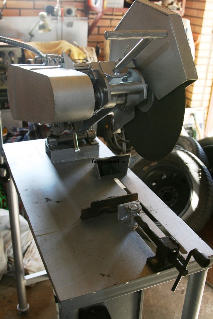
I have long wanted to build a workshop for myself abrasive - metal cutting machine. Cutting metal with a grinder is not always convenient. An angle grinder does an excellent job of cutting sheet steel, but cutting off corners and profile pipes evenly with an angle grinder takes a long time and is not always convenient. It is necessary to mark on all sides and cut the workpiece on one side. Cutting is done on the ground in a bent position, holding the workpiece with your foot. Your back gets tired and sparks fly in all directions. And cut straight round pipe even more difficult and longer. It is more convenient to do this on metal cutting machine, when there is no need to bend over, and the workpiece is securely and securely fixed in the machine. It is very convenient to make or on such a machine. The machine was made from “what was at hand.” I tell and show you what I got, and you make your own adjustments and make the machine even better from “what is at hand” at your disposal. I do not consider it advisable to describe the entire manufacturing process in detail; I will only focus on the important (in my opinion) points.
The manufacturing process must be performed in the following order:
- Manufacturing the shaft on which the cutting disc and drive pulley will be installed. Assembling the entire assembly and installing it on the pendulum (I call the pendulum the upper, movable part of the machine on which the cutting disk and motor are installed).
- Engine installation. Connecting the motor to the cutting disc shaft with a drive belt.
- Manufacturing protective covers for cutting disc and drive belt.
- Manufacturing the pendulum mounting shaft
- Manufacturing of a machine frame with a device for securing the workpiece, a spark arrester, preparation for installing electrical...
- Installing the pendulum on the frame.
- Wiring.
- Test run. Adjustment and debugging.
I made the machine in a different sequence and was faced with constant alterations and adjustments, which caused the process to drag on. If I decided to make a machine now, I would do everything in this order.
Before starting to make the cutting machine, I studied the experiences of other people, from which I realized that:
- The motor must be installed at least 3 kW. if the cutting disc is 400 mm.
- The disk speed must be at least 3000 per minute.
- It is more convenient to place the disc on the shaft on the right, and the drive pulleys on the left; this will not allow the nut securing the cutting disc to turn loose during operation.
- bearings for the cutting disc shaft are suitable for both 205 and 204 (I used 205)
I installed a 3-phase motor, since I have a 380V voltage in my workshop. If your voltage is 220 V, in this case you will have to install starting capacitors; there is a lot of information on how to do this on the Internet.
Next, look at the photographs of the manufacturing process.


The protective cover lifts up to replace the used disc with a new one. To do this, you need to unscrew just one M8 bolt from above.


Possibility of adjusting the tilt of the rocker using metal plates. I did not install bearings on this shaft, but simply drilled holes for lubrication on top and plugged them with M6 bolts.

I borrowed the vice for clamping the workpiece from an old factory-made cutting machine, but I had to modify it a little. In this vise, the clamping screw nut can be divided into two halves, which is very convenient when installing and removing the workpiece.
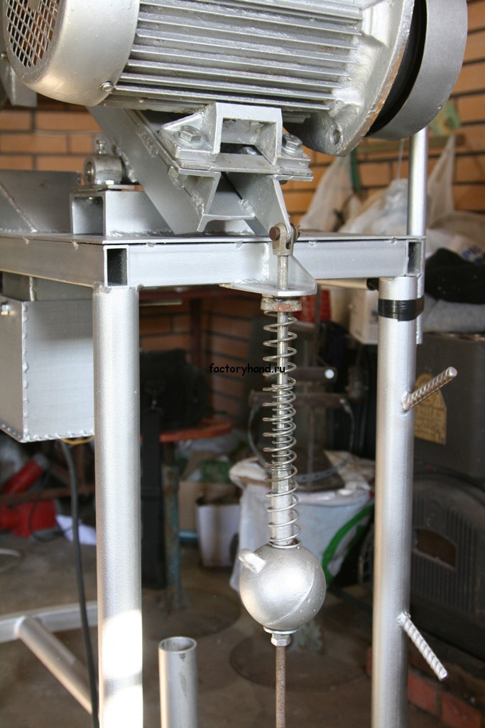
There is no need to create a return mechanism; just change the alignment of the rocker shaft.

Spark arrester. 97 percent of all sparks end up in a removable container.
Using the stop bolt (bottom), you can adjust the maximum angle of inclination.

How to calculate the required pulley diameter.
We will assume that the cutting disc should rotate at a speed of 3000 rpm. The discs contain information about the maximum permissible rotation speed of 4400 rpm. So you decide for yourself at what speed your disk will rotate, the main thing is that it should not exceed 4400 rpm.
To calculate pulley diameters you need to know:
- engine speed
- cutting disc shaft rotation speed
Calculation example:
Our engine rotates at a speed 1500 rpm
The cutting disc must rotate at a speed 3000 rpm
We have a pulley for the shaft of a cutting disc with a diameter 65 mm.
What kind of shaft should be on the engine?
- We calculate the length of the perimeter of the existing shaft: number Pi (3.14) multiply by the diameter. 3.14 x 65mm = 204.1 mm (shaft perimeter length).
- multiply the resulting number by required speed shaft: 204.1 mm x 3000 rpm = 612,300 mm/min.
- divide what you get by the engine speed: 612 300 mm/min / 1500 rpm = 408.2 mm (engine pulley perimeter)
- divide the result by Pi: 408.2mm / 3.14 = 130 mm We need a pulley of this size in order to spin the cutting shaft at a speed of 3000 rpm.
- Do you have pulleys of other diameters available?
- You only have a suitable pulley for the engine and you need to select a pulley for the cutting disc shaft
- You don't have pulleys yet and are planning to buy or make them.
How to calculate the length of the drive belt?
The following data will be required for the calculation:
- drive pulley radius
- driven pulley radius
- distance between pulley centers.
Calculation example.
We have two pulleys with a diameter 65mm And 130mm, respectively, their radii 32.5mm And 65mm. The distance between their centers is variable (in order to tension the drive belt), for an example calculation we take the length between the centers 500mm.
We count half the circumference of each pulley in millimeters and add to the resulting number two distances from their centers (since the belt passes from one pulley to another and returns back to the first).
32.5mm x 3.14 (Pi) = 102.05mm (half circumference of the first pulley)
65mm x 3.14 = 204.1mm (circumference of the second pulley)
102.05 + 204.1 + 500 + 500 = 1306 mm (required drive belt length).
For a more accurate calculation, you need to takeminimum And maximum the length of the distance between centers, choose something in between that suits you.


A pendulum saw for metal, in fact, is a cutting machine whose tasks include: cutting pipes, profiles, metal angles, different angles. The machine is a rigidly fixed frame, with a pendulum mechanism, which allows cutting to exactly the size and intended angle. Mainly on the market Makita tools are presented, which guarantees high quality and efficiency, but there are also products from lesser-known manufacturers.
Device
Pendulum feed mechanism cutting tool involves a top-down working movement, through mechanical or manual control. One of the advantages pendulum machine is also a change in the cutting angle, up to 45 degrees from the normal. The working part of the machine is a circular saw; depending on the type, the machine can be single- or double-headed, depending on the number of cutting saws.
The circular saw located on a pendulum mechanism can be driven either manually by an employee or automatically.
The machine is often installed graduated dials, for additional control of cutting accuracy, for example, a Makita LC1230 machine, in this case the cutting angle is changed by turning the handle.
Advantages and disadvantages
When fully equipped, the pendulum saw is absolutely safe and comfortable to use. The dust collector collects abrasive elements and metal particles. The clamp for securing the workpiece holds the part to be sawn and prevents the blade from skewing.
Advantages of pendulum cutting machines:

Disadvantages: the only disadvantage of this type of machines is their high cost in professional performance. Yes, a pendulum saw Makita costs from 10 thousand rubles. But at the same time, Makita tools are most valued by our industrialists. Makita produces power tools and components, the same saw blades, high quality and different prices, from household models, to highly professional equipment.
Assembly saws
 A special subtype of pendulum cutting machines is characterized by a simplified design and increased mobility. Assembly machines do not have a mechanism for turning the saw itself and cut the workpiece only along the normal.
The device in this case simplified as much as possible, saw, pendulum, bed. Discs for cutting metal are usually abrasive; carbide is less commonly used.
The drive on a disk, in professional cutting machines, is usually belt driven, this allows you to reduce the load on the engine and avoid sudden jerks.
Due to the lack of hard fastening the pendulum and the workpiece, when working with cutting-off assembly machines, it is necessary to take into account the following nuances:
- Use a clamp to secure the workpiece while cutting.
- At the moment of starting, the torque of the disk gives a strong push to the saw, take this into account.
- When cutting with a mounting machine, a burr is formed on the workpiece, which must subsequently be removed.
Making a pendulum machine with your own hands
 To do this, it is enough to make a frame from a channel and a corner; you can use a regular one as a working tool circular saw, securing it to the frame.
Open the bed, it’s quite simple to do, install two channels - paws, connecting them in pairs. Weld the base of the pendulum to them. Often a solid piece is used as a base. metal plate 12 mm thick, in this case the hole for the saw blade is simply cut or drilled. Need a drilling machine.
After this, it is necessary to make cages for bearings for the pendulum; for this, it is best to contact a turning shop. After turning, welding will be required.
Also during the creation of parts rotary machine and you will need a pendulum milling machine and drilling.
Don’t forget about casings; for their manufacture it is best to use sheet metal 0.8–1 mm thick. Cutting is done according to ready-made patterns, after which it is tacked by spot welding.
During processing and workpieces the following were used:
- Gas cutter, cutting base metal, pendulum and frame blanks.
- Screw-cutting lathe for turning fingers and clips.
- Milling machine for processing the edges of workpieces and milling part of the pendulum parts.
- Drilling machine.
- Welding transformer.
Overall it turns out that the price self-made the frame for the pendulum saw is large, the forces of an entire mechanical repair shop will be required. In some cases it's worth it, sometimes not. The price is too high.
Sometimes it's easier and more efficient to buy already ready-made tool. This will save time and money.
Cutting tool
 The saw uses as a cutting tool circular saws, abrasive wheels different diameters and seats. In this case it is necessary See the saw's operating manual; the recommended blade parameters are indicated there. Thus, the Makita LC1230 saw uses a disk with a diameter of 12, with an inch fit, 25.4 mm and a number of teeth of 60 for cutting. This could be a Makita saw blade, 305x25.4x60, for example, Makita B-29393. Discs from other manufacturers that are suitable for technical specifications. Cutting is usually done with carbide-tipped discs at the ends of the disc teeth.
Exploitation
Before using the machine must be installed on a raised table or workbench, this is necessary for the comfort of its use. It is also necessary to make room for cutting, carrying material and storing workpieces.
The Makita LC1230 saw is compact; installation requires small area, but we must not forget about the movement of material and workpieces, as a result work zone cutting saw is a rectangle of 2x4 meters. With a material length of 2–3 meters.
Cutting with a pendulum saw is not a difficult task, but nevertheless requires attentiveness and accuracy. Yes, special danger represent sparks and hot metal particles flying from under the saw. Partially, the collar installed on the saw body saves you from them. But nevertheless, we should not forget about personal protective equipment.
Nowadays, there are a huge variety of different tools for cutting metal. Many of them are manual and have a large number of inconveniences. The rest of the tools are considered automated and have large dimensions or a large price category.
To combine business with pleasure, as well as convenience and price range, handicraft masters created a disc cutting machine. Below we will look at everything related to this equipment.
The scope of application of this machine equipment extends to industrial area applications and for domestic use. Used for cutting various types metal (steel, cast iron, copper, aluminum, etc.).
Since in everyday life there are a huge variety of different metal objects required minor repairs, this machine becomes extremely necessary. After all, lowering the cutter stand with the cutting disk once will be easier and faster than manually sawing with a hacksaw.
Dimensions homemade equipment allow you to place it under a canopy in the summer, and in winter safely place it in a warm garage or workshop.
Tip: It is extremely important to choose a smooth and solid place to install the bed ( concrete slab, thick corners, or concrete support legs bed). This is done in order to reduce the possibility of vibration to a minimum during operation.
Mainly used in production automated systems, which are controlled by the operator via CNC. The goal is mass production of metal products, in the form of cutting pipes of given sizes and various sections, flat rolled metal and much more.
Below we will look at the criteria by which this machine equipment is distinguished.
Classification of cutting machines
All cutting machines are distinguished according to a huge number of criteria. We'll look at the most important ones. So, the main technological criteria:
By type of toolkit
The separation occurs directly on the tool that cuts the metal products. In turn, they are divided into the following subspecies:
Band saws
In this case, a band saw with teeth is used. The belt is made from high-quality high-speed steel. Due to the fact that the cutting tape is thin, there is a saving in material consumption due to the thin cut. Apply band machines in production.
Hacksaws
They are used in small industries, as well as in everyday life. Hacksaw tools can be hand-held (the well-known hacksaw for metal) or an electromechanical machine. In this case, the hacksaw blade is made of various metals (high-speed steel, carbon steel, alloy steel, bimetallic steel). This type is quite easy to operate and is considered a convenient tool.
Disc machines
Belongs to the category indispensable tools. Used throughout the metalworking industry. Using such equipment, high-quality cutting of metal can be carried out even by an unqualified person. In addition to industry, this machine equipment is widely used in everyday life.
By number of cutting edges
Single head
The design contains one cutting disc. This type of machine is low-productive of its kind and is capable of performing only one operation.
Double head
Their design uses two “heads” for attaching disks. In this case, one “head” is firmly fixed and motionless. The second has the ability to move in independence in the first. This equipment is considered a high-performance tool.
By type of saw blade feed
Front saw blade feed
The center of the disk moves in a horizontal plane.
Bottom feed
The center of the disk moves from bottom to top along a vertical plane.
Pendulum feed
The center of the cutting disc moves like an arc, from top to bottom.
Vertical feed
The center of the disk moves along a horizontal plane from top to bottom.
By main type
Cut-off saws
This tool is used to cut dimensional pieces of rolled metal. Well suited for small-scale production.
Abrasive - cutting
When working with such equipment, abrasive wheels are used. High-quality cutting of metal residues (burrs) is carried out. Cutting the material into blanks, cutting profile metal at the required angle from 0 to 45 degrees.
Correctly-cutting
Such equipment processes metal produced and supplied on coils (reinforcing steel, metal strip, wire, rods with a profile section). This equipment is equipped with the correct mechanism and automatic unwinding of metal from the reel. The twisted wire enters this mechanism, is straightened over the entire plane and fed into a special receiver for further processing.
Tip: Depending on the material to be cut, you need to select suitable cutting discs. The discs must meet the technical specifications.
Disc machine device
Frame
Or metal structure, playing the role of the base of the unit.
Pendulum unit
This is a kind of metal part made of a metal profile, which looks like the letter “T”. The movable side is mounted on a bracket located on the frame. The movement of the pendulum is carried out by means of bearings, and the return to its original position is carried out by a flexible part (a strong harness or a small spring).
Pipe clamp
The so-called vice, mounted on the bed. They allow you to press the workpiece to give it a stationary position.
Pendulum unit axis
This axis is used to move the disk.
Electrical engine
The heart of the unit. It is he who puts the whole mechanism into action. An asynchronous motor is used for this equipment.
Actuator
A box containing electronics that is connected to electrical network. On this box there are buttons to turn it on and off.
Wheel protective cover
Steel protection that prevents fragments from the disk from falling directly into the person working on the unit.
Belt guard
Located where the belt makes its movement. This casing is designed to protect a working person from being hit by a belt if it breaks.
Pendulum assembly handle
That part with the help of which pressure is exerted by the cutting disk on the workpiece.
Ground bolt
As with all machines, there is a bolt on the body of the unit that is used for grounding.
Abrasive wheel
Direct cutting disc consisting of various materials.
Sling brackets
(4 units)
bed
This is the area where the main unit of the unit is located.
Adjustable stop
Due to it, it is fixed right size future product.
Tip: If your budget is quite modest, then you can use scrap materials to create parts of the unit. If your budget allows, then it is advisable to purchase all the components in the store. This will improve performance and service life.
Manufacturing of a disc cutting machine

Any invention will require certain parts, whether purchased elements or homemade parts. To create a cut-off brainchild you will need the following:
- Metal corner with dimensions No. 24.
- Metal channel No. 10.
- Movable shaft.
- Tubes for making a handle.
- Welding machine.
- Bearings for the pendulum mechanism.
- Electric drive.
- Box for storing electronics.
- On/off toggle switch.
- Starting circuit.
- Winding.
- Electric drill.
- Fastening elements (bolts, screws).
Let's look at the progress of assembling all the equipment:

- First of all, with a grinder, blanks are cut into a frame with dimensions of 400x600x1200 mm.
- Using welding, the frame is assembled from prepared parts.
- A channel is welded over the entire frame. It will give additional strength to the machine and serve as a guide.
- Several vertical supports are screwed onto the channel.
- Next, the next frame is installed, on which the engine and shaft will be located. The frame dimensions should be 400x600 mm.
- A plate intended for the engine is attached to the frame. The best electric motor for these purposes is an asynchronous motor. Its power should be from 1.5 to 3 kW. After installing the engine, it is necessary to connect it to a three-phase network.
- The shaft, flanges, supports with a pulley are made on a lathe.
- Next, the bearings and pulley are installed.
- The box in which the circuit is located is installed in the lower part of the frame.
- A shaft with a sleeve is inserted between the vertical supports. Shaft diameter 12 mm. The gap between the bushing and the shaft should be kept to a minimum.
- On both sides of the bushing, limiters made from pieces of channel are welded.
- An electric motor and a cutting mechanism are installed on a long support beam and on pieces of channel.
- The final step is to install the belt that connects the shaft and the motor.
Based on the above assembly steps, we can conclude that it will be much cheaper to assemble such a unit with your own hands. Moreover, during the assembly process, you yourself adjust the entire mechanism, as they say, for yourself.
Connecting a button that is intended for emergency situations, carried out directly, and the engine through a box with a circuit and an automatic machine.
Tip: If you have assembled such a structure with your own hands at least once, you can easily repair such units. This is because you will know the entire mechanism of such a machine by heart.
Manufacturing a cutting machine based on a grinder

In addition to the classic variation of the cutting machine
There is also a simplified version of the machine using a grinder (angle grinder). In this case, a frame is made into which the second frame is attached to the sleeve. It is on the second frame that the angle grinder is secured using metal fasteners.
In order for the grinder to return to its original position, it is necessary to secure the frame and grinder with a tight rubber band or spring. The frame itself is mounted on a prepared bed or on a large and heavy table. The heaviness of the table will ensure a minimum of vibration. If a frame is being prepared, then it must be mounted on a foundation prepared in advance. Such an invention can serve as a good tool in a home workshop or as an excellent device for cutting metal.
General reviews about the machine
If you search for reviews on the Internet about this unit, you will find only positive reviews. Indeed, such an invention is very convenient in its own way. With its help, you don’t need to suffer with the grinder in your hands, in a bent state. If you choose a cutting tool for certain jobs, then only a disc cutting machine.
Video reviews
Video review of the disc cutting machine:
Video review of a cutting machine using a grinder instead of a disk:
Video review of the assembly of a homemade machine:
Video review of the cutting machine:
It is useful to replenish the arsenal of metal-cutting machines in a home workshop with a pendulum saw. You can fix it on a workbench, next to a bench vice in which the workpiece is clamped. The working tool of the saw is an abrasive disc. He can handle steel bars, angles, pipes, sheets and even Metlakh tiles, porcelain and glass, hardened to any hardness, and the cut surface is quite clear. If you replace the disk with a saw with a fine tooth, you can cut wood, plywood or plastic, while a diamond blade will make it possible to process stones.
To secure the workpiece, it is convenient to use a rotary vice; in this case, cutting can be done at an angle, which is very convenient when preparing parts for welding.
Various attachments to the saw allow you to make shallow cuts and grooves and even turn it into a regular “circular saw”.
For such a saw you will need a single-phase electric motor with a power of 340 W (from an electric sharpener) or a three-phase type AOL 21-2 with a power of 400 W and a rotation speed of 2800 rpm. The rotation is transmitted to the machine spindle by a V-belt type A-I018 from a GAZ-24 car.
1 - electric motor, 2 - support, 3 - tool protective casing, 4 - tool (abrasive disc), 5 - belt protective casing, 6 - A-1018 V-belt, 7 - M8X14 mm screw, 8 - drive pulley (D 16) , 9 - belt casing cover (steel), 1C - driven pulley (D 16), 11 - spacer sleeve (steel), 12 - washer (steel), 13 - pendulum feed handle, 14 - bolt M6X12 mm, 15 - screw M5 X10 mm, 16 - shaft (steel), 17 - cover (D 16), 18 - cover (D 16), 19 - sleeve (steel), 20 - washer (steel), 21 - nut (steel), 22 - ball bearing No. 203. 23 - body (steel), 24 - boss (steel), 25 - M6X8 mm screw. 26 - M8 X 16 mm screw, 27 - boss (steel), 28 - frame (steel), 20 - M6X16 mm bolt, 30 - 1/2"" pipe (steel), 31 - axle (steel), 32 - bushing (steel), 33 - washer, 34 - M10 nut, 35 - plate (steel), 36 - intermediate housing (D 16).
The basis of the saw is a square-section spinal frame, to which the spindle body is welded on one side, and on the other, a plate for installing the motor. A 1/2" pipe is passed through the groove in the frame - it is the body of the saw's swing axis. When performing welding work, make sure that the axis of the motor shaft, the spindle shaft and the swing axis of the saw are strictly parallel. After welding, be sure to straighten the frame, clean the welds and paint it with nitro enamel with a preliminary primer.
The belt casing and abrasive disc casing are made of 2 mm thick sheet steel. It is best to weld workpieces from the inside using a fillet weld. The belt casing is screwed directly to the engine and frame, to which the abrasive disc casing is also screwed. The drive handle is located on the removable belt housing cover.
Before assembly, fill the spindle bearings with CIATIM-221 grease. Insert felt rings soaked in liquid lubricant into the bearing grooves.
When the saw is assembled, the motor must outweigh the spindle and be located below, between the supports, otherwise, when the saw is turned on, the abrasive may hit the workpiece and crumble.

Rice. 2 Pendulum saw accessories:
A - for cutting grooves:
1 - belt drive casing, 2 - bracket, 3 - work table fixed in a vice;
B - for cutting sheet material:
1 - belt drive casing, 2 - folding table, 3 - hinge, 4, 5 - brackets.
When working on a pendulum saw, you must strictly follow safety regulations. The power cable must be protected from mechanical damage a steel flexible hose, which can be taken from a shower hose. The electric motor, as well as the saw itself, must be reliably grounded. Secure the working tool to the shaft only with a nut with a left-hand thread. Operating a saw without safety glasses is dangerous.
If the drive belt becomes loose during operation of the device, it must be tightened, for which it is enough to lay a plate of the required thickness between the frame plate and the engine.
V. ZAYTSEV, design engineer
"Modelist-Constructor" 1985, No. 12