During machining various materials may form large quantities o shavings. With its removal manually many difficulties arise. To significantly simplify the procedure under consideration, special devices called chip ejectors began to be used. They can be found in specialized stores; the cost varies over a fairly wide range, which is associated with functionality, performance and popularity of the brand. If desired, such equipment can be made with your own hands, for which it is enough to know the types and principles of operation.
Principle of operation
You can do a cyclone-type chip ejector with your own hands only after determining the basic principles of operation. The features include the following points:
- A corrugated hose of small cross-section is connected to the main body, which concentrates and enhances traction. The tip may have different attachments, it all depends on the specific task at hand.
- At the top of the structure there is a motor, which is directly connected to the impeller. During rotation, the air is discharged, thereby creating the required thrust.
- During suction, the chips settle in a special container, and the air is discharged through a special pipe on which a coarse filter is installed.
- A fine filter is also installed at the outlet pipe, which traps small particles and dust.
In general, we can say that the operating principle of cyclone-type chip ejectors is quite simple, due to which the design is characterized by reliability.
Types of chip ejectors
Almost all models of cyclone chip ejectors are similar. In this case, the main mechanisms, for example, the engine or the cyclone system, may differ slightly, which determines the main classification. All cyclone type chip extractors can be divided into several categories:
- For household use.
- Universal.
- For professional use.
When choosing a model for a home workshop, you should pay attention to the first two groups of equipment. This recommendation is due to the fact that their cost should be relatively low, while the performance will be sufficient.
If you frequently carry out work in the workshop, there is a large amount of shavings, and if you are providing professional cleaning services for workshops and other premises, you should consider when choosing cyclone-type chip ejectors from the professional group. This is due to the fact that it is characterized by more high performance and reliability, can withstand long-term use.
Cyclone type chip suction device
Most models resemble a regular vacuum cleaner, which, due to its strong traction, sucks up large and small chips. However, even a powerful and high-quality vacuum cleaner cannot be used to clean the workshop. Main structural elements can be called:
- A flange-type electric motor is installed, the power of which is only 3.5 kW.
- To discharge the air, a fan with a durable and mechanically resistant impeller is installed. It must be large enough to produce the required thrust.
- The cyclone is designed to purify the air that will be exhausted outside. Its device is designed to filter large elements.
- A multi-stage filter significantly increases the efficiency of the procedure. This is due to the fact that at the primary stage, large elements are separated, after which small ones are separated. Through multi-stage cleaning, you can significantly extend the life of the filter and increase its efficiency.
- The lower cyclone is intended for direct collection of chips.
- A collection bag made of durable material is designed to temporarily store chips and other debris that have been separated from the passing air flow.
High-quality models have a sealed body, which is lined with sound-absorbing panels. To control a cyclone-type chip extractor, an electrical or mechanical unit is placed; there must be a special hole for connecting a corrugated hose with a nozzle.
It is not difficult to make a cyclone-type chip extractor with your own hands, since it is in many ways reminiscent of a conventional vacuum cleaner with a large number of filter elements and high power. The woodworking cyclone device is characterized by high reliability; if the operating instructions are followed, the device will last a long time.
Design features
In most cases, when self-production A cyclone-type chip ejector is equipped with a low- and medium-capacity motor, which can be powered from a standard 220V network.
More powerful units are equipped with three-phase motors, powered by living conditions Quite a lot of difficulties arise.
Among design features It should be noted that the impeller is installed to ensure spiral turbulence of the air flow. In this case, heavy particles are dumped into a special container, after which centrifugal force again lifts the air to remove it.
Preparatory work
When making a structure with your own hands, you can save a lot, but some mechanisms still cannot be assembled yourself. An example would be the most suitable motor and impeller. TO preparatory stage The following actions may include:
- Formation of an action plan for assembling homemade equipment.
- Searching for a suitable electric motor, checking its condition.
- Selection of other mechanisms that cannot be made by hand.
In a carpentry workshop, much of what is required to create cyclone-type chip ejectors can be made with your own hands.
Tools
Depending on the chosen scheme, the most various instruments. The easiest way is to make the outer casing from wood. It is to this that other elements will be connected. The recommended set of tools is as follows:
- Indicator and multimeter.
- Chisel and other tools for working with wood.
- Screwdriver and various screwdrivers, hammer.
The simplicity of the design determines that it can be manufactured with the most common tools.
Materials and fasteners
The device being created must be light and airtight, and also withstand the pressure exerted by air swirling. To make it you will need:
- The body can be assembled from plywood, the thickness of which is about 4 mm. Due to this, the structure will be durable and lightweight.
- To make other parts, you will also need pieces of wood of various thicknesses.
- Polycarbonate.
- The filter can be taken from a VAZ injection type. Such a filter is cheap and will last quite a long time.
- The engine can be removed from an old powerful vacuum cleaner, the impeller will be mounted on the output shaft.
- To connect the main elements you will need screws, self-tapping screws, bolts with nuts, and sealant.
After finding everything you need, you can start doing the work.
Making a cyclone filter
As previously noted, making a filter is quite difficult; it is best to purchase a cheap one already ready-made option execution. However, it will also require a sealed seat.
The seat is also made of wood. In this case, the main thing is to correctly choose the appropriate diameter of the outlet hole, since too small will lead to a decrease in throughput. There is no need to attach the filter, just create a block for it that will fit perfectly in size.
Creating a retaining ring and a shaped insert
To fix the polycarbonate during the manufacture of the case, wooden rings are required. They must have an internal diameter that provides the required volume storage tank. Between the two fixing rings there will be vertical strips holding the polycarbonate sheets.
You can make such rings in a home workshop if you have the appropriate skills and equipment. At the same time, do not forget that they must have high strength.
Installing the Retaining Ring
Assembling the case can begin by placing the locking wheels and polycarbonate sheets. Among the features this stage The following points can be noted:
- The sheets are fixed on both sides with strips.
- The connection is made using self-tapping screws.
- To improve sealing, slots are created in the lower and upper rings for sheets, after installation of which the seams are sealed with sealant.
After assembling the housing, you can begin installing other structural elements.
Installing the side pipe
In order to eliminate the possibility of rupture of the structure due to clogging of the filter element, a side pipe with safety valve. To do this, a hole is created in the polycarbonate sheet, which is closed on both sides by the body of the safety pipe.
A rubber gasket should be placed between the wooden planks and the wall; the degree of sealing can be increased by using sealant. The element is secured to the body using bolts and nuts.
Top entry installation
Suction of chips and air occurs from the top of the structure. To accommodate the upper input, a small housing is created in which the pipe from the old vacuum cleaner is placed.
When using a special pipe, reliable fixation of the suction hose is ensured, which, moreover, can be quickly removed if necessary. That is why you should not make it yourself.
Installing a shaped insert
A shaped insert is also required to connect the inlet pipe. It must be positioned so that air containing particles can flow in without difficulty.
As a rule, the figure is located opposite the fan, due to which the air flow swirls. It is best to seal the seams with sealant, which will increase the degree of insulation of the structure.
Cyclone filter assembly
After creating a housing to house the filter, it needs to be installed in its place. It is worth considering that there will also be electronic elements inside that provide power to the electric motor.
Another pipe is removed from the outer part of the cyclone filter housing. It will be needed to divert the air flow.
Principles for choosing a chip ejector and the main manufacturers
Quite a large number of different companies are engaged in the production of cyclone-type chip ejectors. The principle of operation of the device is no different, only the power and reliability of the design increases.
Cyclone-type chip ejectors from foreign brands are more popular; domestic ones are cheaper, but last much less.
From the very beginning of working in the workshop I encountered the problem of removing dust after work. The only available way to clean up the floor was to sweep it. But because of this, an incredible amount of dust rose into the air, which settled in a noticeable layer on furniture, on machines, on tools, in hair and in the lungs. The concrete floor in the workshop made the problem worse. Some solutions have been to spray water before sweeping and use a respirator. However, these are only half measures. In winter, water freezes in an unheated room and you have to carry it with you; in addition, the water-dust mixture on the floor is difficult to collect and also does not contribute to workplace hygiene. The respirator, firstly, does not block 100% of the dust, some of it is still inhaled, and secondly, it does not protect against dust settling on the environment. And not all nooks and crannies can be reached with a broom to pick out small debris and sawdust.
In such a situation, the most effective solution it would be to vacuum the room.
However, using a household vacuum cleaner will not work. Firstly, it will have to be cleaned every 10-15 minutes of operation (especially if you work on milling table). Secondly, as the dust container fills up, the suction efficiency decreases. Thirdly, the amount of dust greatly exceeding the calculated values will greatly affect the service life of the vacuum cleaner. Something more specialized is needed here.
There are many ready-made solutions for dust removal in the workshop, however, their cost, especially in light of the 2014 Crisis, does not make them too affordable. Found it on thematic forums interesting solution- use cyclone filter in combination with a regular household vacuum cleaner. All of the listed problems with household vacuum cleaners can be solved by removing dirt and dust from the air to the standard vacuum cleaner dust collector. Some people assemble cyclone filters from traffic cones, others from sewer pipes, others from plywood and whatever their imagination allows. But I decided to buy it already ready filter with fasteners.
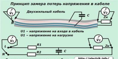
The principle of operation is simple - the air flow swirls in a cone-shaped filter housing and dust is removed from the air under the influence of centrifugal force. In this case, the dust falls through the lower hole into the container under the filter, and the purified air exits through the upper hole into the vacuum cleaner.

One of the common problems in the operation of cyclones is the so-called “carousel”. This is a situation where dirt and sawdust do not fall into the dust collection container, but endlessly swirl inside the filter. This situation arises from too high a flow rate of air created by the turbine of the vacuum cleaner. You need to reduce the speed a little and the “carousel” will disappear. In principle, it does not interfere - the next portion of garbage is pressed into the container most from the “carousel” and takes its place. And in the second model, plastic cyclones of this carousel practically do not exist. To eliminate air leaks, I coated the junction of the filter with the lid with hot glue.

I decided to get a larger dust collection container so that I would have to take out the trash less often. I bought a 127 liter barrel, apparently made in Samara - just the right size! I'm going to carry the barrel to the trash can like a grandmother carrying a string bag - on a different cart, so as not to strain herself.

Next is the choice of layout. Some install the dust collection unit permanently and lead channels to the machines. Others simply place a vacuum cleaner and a barrel next to each other and drag them to the desired location. I wanted to make a mobile unit on wheels to move everything around the workshop in one unit.
I have a rather small workshop and the issue of saving space is very relevant. Therefore, I decided to choose a layout in which the barrel, filter and vacuum cleaner are located one above the other, occupying a minimum area. It was decided to make the body of the installation from metal. Frame from profile pipe determines the dimensions of the future installation.

When installed vertically, there is a risk of tipping over. To reduce this probability, you need to make the base as heavy as possible. For this purpose, a 50x50x5 corner was chosen as the material for the base, which took almost 3.5 meters.

The noticeable weight of the cart is compensated by the presence of swivel wheels. There were thoughts, if the structure was not stable enough, to pour lead shot or sand into the cavity of the frame. But this was not required.

In order to achieve verticality of the rods, I had to use ingenuity. The recently purchased vice came in handy. Thanks to such simple equipment it was possible to achieve precise installation corners

It is convenient to move the cart while holding the vertical bars, so I reinforced their attachment points. In addition, this is an additional, albeit not large, weighting of the base. In general, I like reliable things with a margin of safety.

The barrel will be fixed in the installation frame using clamps.

At the top of the rods there is a platform for the vacuum cleaner. Next, holes will be drilled in the corners at the bottom and the wooden planks will be secured using self-tapping screws.

Here, in fact, is the entire frame. It seems to be nothing complicated, but for some reason it took four evenings to assemble it. On the one hand, I didn’t seem to be in a hurry, I worked at my own pace, trying to complete each stage efficiently. But on the other hand, low productivity is associated with the lack of heating in the workshop. Safety glasses and a welding mask quickly fog up, impairing visibility, and are bulky outerwear hinders movement. But the task is completed. Besides, there are only a couple of weeks left until spring.

I really didn't want to leave the frame like this. I wanted to paint it. But on all the cans of paint that I found in the store it is written that they can be used at a temperature not lower than +5, and on some even not lower than +15. The thermometer in the workshop shows -3. How to be?
I read thematic forums. People write that you can safely paint even in cold weather, as long as the paint is not on water based and there was no condensation on the parts. And if the paint has a hardener, don’t worry about it at all.
I found in the caches an old, slightly thickened can of Hammerite, which I used to paint a horizontal bar at the dacha back in the summer - . The paint is quite expensive, so I decided to test it in extreme conditions. Instead of the expensive original solvent, Hammerite added a little regular degreaser to make it a little thinner, stirred it to the desired consistency and began painting.
In the summer this paint dried in one hour. It’s hard to say how long it took to dry in the winter, but when I returned to the studio by the evening of the next day, the paint was dry. True, without the promised hammer effect. It's probably the degreaser that's to blame, not negative temperature. Otherwise, no other problems were found. The coating looks and feels reliable. Perhaps it’s not for nothing that this paint costs almost 2,500 rubles in the store.

The cyclone body is made of good plastic and has fairly thick walls. But the attachment of the filter to the barrel lid is quite flimsy - four self-tapping screws screwed into plastic. In this case, significant lateral loads may occur on the hose, which is attached directly to the filter. Therefore, the attachment of the filter to the barrel needs to be strengthened. People have different approaches to solving this problem. Basically they collect additional frame hardness for the filter. The designs are very varied, but the idea is something like this:

I approached this a little differently. I welded a holder for pipes of a suitable diameter onto one of the rods.

In this holder I clamp the hose, which bears all the twisting and jerking. Thus, the filter housing is protected from any loads. Now you can pull the unit directly behind you by the hose without fear of damaging anything.

I decided to secure the barrel with tightening straps. When I was choosing locks at a hardware store, I made an interesting observation. A five-meter tie-down belt with a foreign-made ratchet lock cost me 180 rubles, and the bare frog-type lock lying next to it cost me 180 rubles. Russian production would have cost me 250 rubles. This is where the triumph of domestic engineering and high technology lies.


Experience has shown that this method of fastening has an important advantage. The fact is that on forums dedicated to these filters they write that barrels like mine, when connecting a powerful vacuum cleaner, can be crushed due to the vacuum that occurs when the inlet hose is clogged. Therefore, during testing, I deliberately blocked the hole in the hose and, under the influence of vacuum, the barrel shrank. But thanks to the very tight grip of the clamps, not the entire barrel was compressed, but only in one place below the hoop a dent appeared. And when I turned off the vacuum cleaner, the dent straightened itself out with a click.

At the top of the installation there is a platform for a vacuum cleaner

I purchased a bagless, almost two-kilowatt monster as a household vacuum cleaner. I was already thinking that this would be useful for me at home.
While buying a vacuum cleaner from an ad, I encountered some inexplicable human stupidity and greed. People sell used items without a guarantee, with a worn-out part of the resource, defects in appearance at prices lower than store prices by some 15-20 percent. And okay, these would be some popular items, but used vacuum cleaners! Judging by the period of posting of advertisements, this trade sometimes lasts for years. And as soon as you start haggling and name an adequate price, you come across rudeness and misunderstanding.
As a result, after a couple of days I finally found it for myself great option for 800 rubles. Well-known brand, 1900 Watt, built-in cyclone filter (the second one in my system) and another fine filter.
To secure it, I couldn’t think of anything more elegant than pressing it with a tightening belt. In principle, it holds securely.

I had to get a little tricky with connecting the hoses. As a result, we have such a setup. And it works!

Usually when you read reviews from the first use of such things, people are choked with delight. I experienced something similar when I first turned it on. It's no joke - vacuuming in the workshop! Where everyone wears street shoes, where metal shavings and sawdust fly everywhere!

I have never seen this concrete floor, which is impossible to sweep due to the dust stuck in the pores, so clean. Persistent attempts to sweep it up only lead to an increase in the density of dust in the air. And such purity was given to me in a couple of easy movements! I didn't even have to wear a respirator!

We managed to collect what was left after the previous cleaning with a broom into the barrel. When the device is operating, thanks to the transparency of the filter, you can observe streams of dust swirling inside. There was also dust in the dust collector of the vacuum cleaner, but there was a small amount of it and it was a particularly light and volatile fraction.

I'm very pleased with the result. There will be no more dust storms in the workshop. You could say I'm moving into a new era.
Advantages of my design:
1. Occupies a minimum area, determined only by the diameter of the barrel.
2. The unit can be carried and pulled by the hose without fear of tearing out the filter.
3. The barrel is protected from crushing when the inlet pipe is clogged.

After some time of using the installation, I still encountered the problem of a lack of rigidity of the barrel.
I purchased a more powerful vacuum cleaner. Household, but it sucks like a beast - it sucks up stones, nuts, screws, tears off plaster and tears bricks out of masonry))
This vacuum cleaner collapsed a blue barrel even without clogging the inlet hose! Tightly wrapping the barrel with clamps did not help. I didn't have my camera with me, it's a shame. But it looks something like this:

On thematic forums they warn about this possibility, but still I did not expect this. With great difficulty, he straightened the barrel and sent it, fairly dented, to the dacha to store water. She is not capable of more.
There were two ways out of this situation:
1. Buy a metal barrel instead of a plastic one. But I need to find a barrel of a very specific size so that it fits exactly into my installation - diameter 480, height 800. A superficial search on the Internet did not yield any results.
2. Assemble the box yourself the right size from 15 mm plywood. This is more real.
The box was assembled using self-tapping screws. The joints were sealed using double-sided foam tape.

The cart had to be altered a little - the rear clamp had to be modified to fit a square tank.

The new tank, in addition to strength and increased volume due to right angles, has another important advantage - a wide neck. This allows you to install a garbage bag in the tank. It greatly simplifies unloading and makes it much cleaner (I tied the bag right in the tank and took it out and threw it away without dust). Old barrel didn't allow this.

The lid was sealed with foam insulation for windows

The lid is held in place by four frog locks. They create the necessary tension to seal the cover on the foam gasket. A little higher I wrote about the pricing policy for these frog locks. But I had to fork out more.

It worked out well. Cute, functional, reliable. How I love.

Article about how I did it homemade construction vacuum cleaner with a cyclone type filter. The performance of this useful homemade product for home You can appreciate it by watching a video of his work.
To demonstrate the work, I collected a bucket of sand. In general, I am satisfied with the result of the work done (given that this is a working prototype layout, so to speak).
I’ll say right away: this article is a statement of my history of creating my first (and, I think, not the last) homemade cyclone vacuum cleaner , and I am in no way going to impose anything on anyone, prove or claim that the solutions described here are the only correct and error-free ones. Therefore, I ask you to be understanding, so to speak, “understand and forgive.” I hope my little experience will be useful to “sick” people like me, for whom “a bad head does not give rest to their hands” (in the good sense of this expression).
I once thought about the upcoming renovation and the ensuing consequences in the form of dust, construction debris, etc. And since it is necessary to groove, saw concrete and “perforate”, the experience of the past suggested that it is necessary to look for a solution to these problems. It is expensive to buy a ready-made construction vacuum cleaner, and most of them are designed anyway with a filter (in some models even with a special “shaker”) or a paper bag + filter, which gets clogged, worsens traction, periodically requires replacement and also costs a lot of money. And I just became interested in this topic, and a “pure sporting interest” appeared, so to speak. In general, it was decided to make a cyclone vacuum cleaner. A lot of information was gleaned here: forum.woodtools.ru I did not carry out special calculations (for example, according to Bill Pentz), I did it from what came to hand and according to my own instinct. By chance, I came across this vacuum cleaner on an advertisement website (for 1,100 rubles) and very close to my place of residence. I looked at the parameters, they seem to suit me - he will be a donor!


I decided to make the cyclone body itself metal, because there were strong doubts about how long the plastic walls would last under the influence of “sandpaper” from a stream of sand and pieces of concrete. And also about static electricity when rubbish rubs against its walls, and I didn’t want the future homemade vacuum cleaner threw sparks at its users. And personally, I think that dust accumulation due to static will not have a positive effect on the operation of the cyclone.
The general scheme for constructing a vacuum cleaner is as follows:

The polluted air passes through a cyclone, in which large particles settle into the lower waste container. The rest goes through the car air filter, the engine and through the outlet pipe to the outside. It was decided to make a pipe for the outlet as well, and the dimensions of the inlet and outlet should be the same. This will allow you to use a vacuum cleaner, for example, to blow something off. You can also use an additional hose to release the “exhaust” air outside so as not to raise dust in the room (this suggests the idea of installing this unit as a “built-in” stationary vacuum cleaner somewhere in the basement or on the balcony). Using two hoses at the same time, you can clean all kinds of filters without blowing dust around (blow with one hose, draw in with the other).
The air filter was chosen to be “flat”, not ring-shaped, so that when turned off, any debris that gets there falls into the garbage bin. If we take into account that only the dust remaining after the cyclone gets into the filter, then it will not be necessary to replace it soon, as in a regular construction vacuum cleaner with a filter without a cyclone. Moreover, the price of such a filter (about 130 rubles) is much cheaper than the “branded” ones that are used in industrial vacuum cleaners. You can also partially clean such a filter with a regular household vacuum cleaner by connecting it to the inlet pipe of the “cyclone”. In this case, garbage will not be sucked out of the garbage disposal. The filter mount is made dismountable to simplify its cleaning and replacement.

For the cyclone body, a suitable one was found very conveniently can, and the central pipe is made from a can of polyurethane foam.

The inlet pipe is made to fit a 50 mm plastic sewer pipe into which the hose in the vacuum cleaner is inserted quite tightly with an appropriate rubber coupling.

The second end of the pipe goes into a rectangle, so to speak, to “straighten” the flow. Its width was chosen based on the smallest diameter of the hose inlet (32 mm) so as not to clog. Approximate calculation: L= (3.14*50 mm - 2*32)/2=46.5 mm. Those. pipe cross-section 32*46 mm.


I assembled the entire structure by soldering with acid and a 100-watt soldering iron (it was practically the first time I worked with tin, except for soldering boats in childhood, so I apologize for the beauty of the seams)


The central pipe was soldered. The cone was made using a pre-fitted cardboard template.


The housing for the auto filter is also made using galvanized templates.


The upper part of the central pipe of the air duct was bent into the shape of a square and the lower hole of the autofilter housing (pyramid) was adjusted to it. Put it all together. I made three guides on the sides of the cyclone can to increase rigidity and fastening. The result is something like this “gravity”.


For the garbage disposal and the engine compartment I used 2 barrels of machine oil (60 liters). A little big, of course, but this is what we managed to find. I made holes in the bottom of the engine compartment for attaching the cyclone, and glued sponge rubber onto the contact surface of the garbage disposal to seal around the perimeter. After that, I cut a hole in the sidewall for the inlet pipe, taking into account the thickness of the rubber cuff.


The “gravitapu” cyclone was secured with M10 studs and nuts with fluoroplastic to prevent unscrewing due to vibration. Here and further, all places where tightness is necessary were connected with a rubber seal (or rubber washers) and auto sealant.


To connect the engine compartment and the garbage bin I used latches from the military wooden boxes(special thanks to Igor Sanych!). I had to ferment them a little in a solvent and “adjust” them with a hammer. Fastened with rivets (with rubber gaskets from the chamber).


After that, for greater rigidity and noise reduction, I foamed the entire structure polyurethane foam. You can, of course, fill everything to the top, but I decided to play it safe in case the need arises to take it apart. In addition, everything turned out quite tough and strong.

For ease of movement and carrying of the garbage bin, I attached 2 door handles and 4 wheels with brakes. Since the waste container barrel has a flange at the bottom, to install the wheels it was necessary to make an additional “bottom” from a plastic sheet 10 mm thick. In addition, this made it possible to strengthen the bottom of the barrel so that it would not “squish” when the vacuum cleaner was running.


The base for attaching the filter funnel and the engine platform was made of chipboard with fastening to the barrel along the perimeter with furniture “Euro-screws”. To fix the engine platform, I glued 8 M10 bolts onto epoxy (I think 4 would be enough). Painted it. I sealed the perimeter of the filter installation site with sponge rubber.


When assembling, I coated the neck of the autofilter housing around the perimeter with sealant and tightened it to the base with flat-headed self-tapping screws.

The engine platform was made from 21 mm plywood. For a more uniform distribution of air over the filter area, I used a router to select a 7 mm recess in the area.


To collect the exhaust air and mount the engine, the plastic engine compartment found in the vacuum cleaner was used. “Everything unnecessary” was cut off from it and the outlet pipe was glued onto epoxy reinforced with self-tapping screws. Everything is assembled together using sealant and using metal profile(thick sponge rubber is inserted into it) is pulled to the engine platform with two long M12 bolts. Their heads are recessed flush into the platform and filled with hot-melt adhesive for tightness. Nuts with fluoroplastic to prevent unscrewing due to vibration.


Thus, a removable motor module was obtained. For easy access to the auto filter, it is secured using eight wing nuts. The oversized washers are glued (the shrouds have not escaped).


I made a hole for the outlet pipe.

I painted the entire “pepelats” black from a spray can, after sanding and degreasing.
The engine speed controller used the existing one (see photo), adding to it homemade circuit to automatically start the vacuum cleaner when you turn on the power tool.


Explanations for the homemade vacuum cleaner diagram:
Automatic devices (2-pole) QF1 and QF2 protect, respectively, the circuits for connecting power tools (socket XS1) and the speed control circuit of the vacuum cleaner engine. When the tool is turned on, its load current flows through diodes VD2-VD4 and VD5. They were selected from the reference book due to the large voltage drop across them with forward current. On a chain of three diodes, when one (let’s call it “positive”) half-wave of current flows, a pulsating voltage drop is created which, through fuse FU1, Schottky diode VD1 and resistor R2, charges capacitor C1. Fuse FU1 and varistor RU1 (16 Volt) protect the control circuit from damage due to overvoltage, which can occur, for example, due to a break (burnout) in the chain of diodes VD2-VD4. The Schottky diode VD1 is selected with a low voltage drop (to “save” the already small Volts) and prevents the discharge of capacitor C1 during the “negative” half-wave of the current through the diode VD5. Resistor R2 limits the charging current of capacitor C1. The voltage received at C1 opens optocoupler DA1, the thyristor of which is connected to the control circuit of the engine speed controller. Variable resistor R4 for regulating the motor speed is selected with the same value as in the vacuum cleaner controller board (it is removed) and is made remote (in the housing from the dimmer) for placement on top cover vacuum cleaner. A resistor R removed from the board is soldered in parallel to it. The “on/off” switch S2 in the open circuit of the resistor R4 is used to manually turn on the vacuum cleaner. Switch S1 “automatic/manual”. In manual control mode, S1 is turned on and the regulator current flows through the chain R4 (R) - S2 is turned on - S1. In automatic mode, S1 is turned off and the regulator current flows through the chain R4 (R) – pins 6-4 DA1. After turning off the power tool, due to the large capacity of capacitor C1 and the inertia of the motor, the vacuum cleaner continues to work for about 3-5 seconds. This time is enough to draw the remaining debris from the hose into the vacuum cleaner.
The automatic start circuit is assembled on breadboard. Switches S1, S2, dimmer housing (to accommodate variable resistor R4) and socket XS1 were selected from one not very expensive series, so to speak, for aesthetics. All elements are placed on the top cover of the vacuum cleaner, made of 16 mm chipboard and covered with PVC edging. In the future, it will be necessary to make insulated housings for the boards to protect live parts from accidental contact.


To power the vacuum cleaner, a three-core flexible cable in rubber insulation KG 3*2.5 (5 meters) and a plug with a grounding contact were selected (do not forget about electrical safety and fight static electricity). Considering the short-term intermittent operation of the vacuum cleaner together with a power tool, the selected cable cross-section is sufficient not to heat up. A thicker cable (for example, KG 3*4) is correspondingly heavier and rougher, which would create inconvenience when using the vacuum cleaner. It was decided to discard the device for winding the cable, which was in the donor vacuum cleaner, since the contacts existing there would not withstand the total load of the vacuum cleaner and power tool.
The top cover is secured with a pin and wing nut.

To make it easier to remove the top cover, the motor is connected to the control circuit via a connector. The motor housing and the vacuum cleaner are connected to a protective grounding conductor. To cool the regulator circuit, I drilled a small hole in the outlet pipe to create an air flow inside the engine compartment housing.

In order to be able to insert a garbage bag into the garbage bin, the top edge was covered with a rubber door seal cut lengthwise.

To prevent the garbage bag from being sucked into the cyclone due to air leaks through leaks, it is necessary to make a small hole in it.

The finalization and testing of the resulting vacuum cleaner took place when the repairs had already begun, so to speak, in “combat” conditions. The traction, of course, is many times more powerful than that of a household vacuum cleaner, which would not be enough for even a couple of minutes of working with construction waste. Relatively heavy concrete debris is almost completely deposited in the garbage container and the additional filter does not need to be cleaned for a long time, while the draft is uniform and does not depend on the degree of filling of the garbage container. Dust from putty (in the form of flour) is very light and, accordingly, is less filtered by the cyclone, which forces you to periodically clean the autofilter. The task of making a vacuum cleaner was not set and therefore no test was carried out for this function.
CONCLUSION and CONCLUSIONS:
The resulting device eventually turned out to be functional and has already been tested during the renovation of one room. Now I consider it more like a working model from the “will it work or not for fun” series.
The main disadvantages of this design:
— relatively large dimensions are not convenient for transportation in a car, although the vacuum cleaner moves around the room very easily on wheels. You can use 30 liter barrels for example. As operation has shown, such a large garbage container is inconvenient to clean, and a bag with a large amount of garbage can tear.
— the diameter of the hose can be increased, for example, to 50 mm and a hose from an industrial vacuum cleaner can be used (but the question of price arises from 2000 rubles). Although even with the existing hose, the debris collects quite quickly, unless, of course, you try to pull in half a brick.
— it is necessary to make an easily removable mount for the additional auto filter and engine for more convenient and quick maintenance and cleaning.
— you can include a thermal relay in the control circuit (just determine the response temperature) to protect the engine from overheating.
Poor screening of light fine dust, which can be solved by introducing a second stage of smaller cyclones.
In conclusion, I would like to thank all my friends who helped with ideas and materials in the construction of this “pepelats”. And a special big thank you to my beloved wife Yulia for supporting me in my hobbies.
I hope my little experience will be useful to readers.
When working in a workshop or at home with a grinding tool, when processing parts and preparing surfaces, the need arises to remove fine dust. And, of course, it is advisable to reduce its concentration even during work by organizing local constant air purification at the workplace.
At enterprises, this problem is solved by installing filter units with a cyclone, which collects and sediments dust with the required efficiency.
In our case it is enough make a vacuum cleaner with a cyclone, thereby saving on the purchase of a construction vacuum cleaner, where such a function is provided by the manufacturer.
The principle of operation of a homemade construction vacuum cleaner with a cyclone filter
There are several options for making a cyclone for domestic needs. To determine the most effective operating scheme for the equipment, you should know the operating principle of this filter.
Cyclone in classic version It is a cylinder and a cone, in the upper part of which there is an inlet for polluted air and an outlet for purified air.
The inlet is made so that the air enters the filter tangentially, forming a rotating flow directed towards the equipment cone (down).
Inertial forces act on pollutant particles and carry them out of the flow to the walls of the apparatus, where dust settles.
Under the influence of gravity and secondary flow, the mass deposited on the walls moves towards the cone and is removed into the receiving hopper. The purified air rises up along the central axis and is discharged through a pipe located strictly in the center of the upper platform of the cyclone.
A prerequisite for effective air purification is the accurate design of the apparatus and the tightness of the cyclone, including in relation to the receiving hopper.
Otherwise, the principle of operation is disrupted and chaotic air movement occurs, preventing dust from settling normally.
In addition, it is necessary to select an engine that sucks in contaminated air, which will ensure optimal parameters equipment operation.
Homemade filter for a construction vacuum cleaner, the variants of which are offered on the Internet cannot be called a full-fledged cyclone.
The most simple circuit Such equipment is a plastic barrel with an embedded inlet pipe tangentially, a built-in filter from a car inside the “cyclone” body, through which purified air is removed and to which a household vacuum cleaner is connected.
The disadvantages of the equipment are the absence of a formed flow swirling along the walls of the barrel and a laminar return flow.
In essence, we get an additional capacity for settling large particles (sawdust, shavings), and fine dust will clog the filter at the outlet, and will require constant cleaning.
To improve the design, we suggest adding a plastic barrel homemade cyclone made from a traffic cone. It is best to install a stationary version of equipment for removing dust from the workplace if work is carried out over several hours.
In this case, we need a radial household fan. And with a one-time connection of the cyclone, it is enough to use a regular vacuum cleaner with adjustable suction power.
Sometimes an additional rheostat is installed to reduce the rotation speed of the vacuum cleaner engine, thereby selecting the parameters necessary for the normal functioning of the filter.
In the following sections of the article we will present you with two options for a cyclone for domestic use.
Selection of equipment - what is needed for work
For the first design option for a permanent installation, you will need the following components:
- Plastic barrel;
- Gray plastic sewer pipe with a diameter of 50 mm;
- Traffic cone;
- Corrugated hoses, reinforced with steel wire or metallized hoses;
- Adhesive for plastic;
- Radial household fan with the ability to change the engine speed and performance equal to six times the exchange of air in the room;
- Plywood 10-12 mm thick.
The second version of the product is the most successful, since in this case the product approaches the functionality of a real cyclone.
To make a filter you will need to purchase:
- Ready-made plastic cyclone made in China;
- A barrel, bucket or other container for making a dust bin;
- Corrugated hoses.
A plastic cyclone is inexpensive, approximately 1500-2500 rubles, and is designed to collect medium and heavy dust. Works great with shavings and sawdust.
Step-by-step instructions for the cyclone assembly process
Our first option is stationary design for workshops with large amounts of dust of various origins.
 Assembling a cyclone filter for a vacuum cleaner
 - First we make the cyclone itself. We make a hole in the plastic cone for passage sewer pipe on a tangent.
- For better connection of the pipe with the cone body, we matt the mating surfaces emery cloth. We glue the seams using a mounting gun.
- In the upper part of the cone we install a vertical pipe, the lower end of which should be below the inlet. In this way we can achieve vortex air movement. The pipe is fixed in a plywood sheet in the shape of a circle with a diameter equal to the size of the base of the cone.
- The prepared cyclone is secured to the barrel lid using a round plywood sheet.
- To plastic barrel when the inlet pipe is clogged with debris, it does not deform under the influence of vacuum; inside the container we install a spacer - a frame made of plywood sheet. External dimensions the frames follow the inner diameter of the barrel. To strengthen the structure, we attach the construction cone to the lid of the container using metal pins.
- Next, we connect the cyclone to the corrugated hoses at the inlet and outlet. We install a radial household fan outdoors under a canopy.
The second version of the construction vacuum cleaner is based on a Chinese plastic cyclone, which is also attached to any of the selected containers. The result is a reliable and efficient design.
The cyclone is attached to the container using a metal clamping flange.
VIDEO INSTRUCTION
When starting the vacuum cleaner and further operation, do not forget to clean the inlet pipe and stop the internal spacers on the containers to prevent deformation of the receiving hopper.
If finer air purification is required, the design is supplemented with a car filter in the housing at the outlet of the product.
Cyclone-type installations are used in industry for purifying gases and liquids. The operating principle of the filter is based on the physical laws of inertia and gravity. Air (water) is sucked out of the device through the upper part of the filter. A vortex flow is created in the filter. As a result, the contaminated product enters the filter through a pipe located on the side of the upper part. Since debris particles are heavier, they settle in the lower part of the filter, and the purified product is discharged through the upper part. Today we will look at just such a filter, made for the workshop, together with the author of the homemade product.
Tools and materials:
76 l waste container;
Plywood;
Polycarbonate;
Plastic pipe;
coupling;
Fasteners;
Masking tape:
Manual frezer;
Electric jigsaw;
Drill;
Glue gun;
Band saw;
Sander.


Then from the lid, using band saw, cuts out a circle with a diameter of 40 cm.


The place of the cut is glued and polished.


In a circle with a diameter of 40 cm, which remains from cutting out the bottom cover, cut out the middle according to the diameter of the plastic pipe. This blank will be installed at the top of the device.

For the side wall, the author used transparent polycarbonate. This will allow you to control the operation of the filter and the filling of the trash can. I rolled up a polycarbonate cylinder and inserted it into the inner hole of the bottom cover. Marked and cut along the joint. I received a cylinder with a diameter of 40 cm and a height of 15 cm.


Having inserted the polycarbonate cylinder into the inner ring of the bottom cover, drill holes in 10 cm increments. Fix the cylinder with self-tapping screws. In order to crush the polycarbonate, the bottom of the screws must be flat.

The top cover is inserted into another part of the cylinder. Secure with tape. After drilling the holes, fasten the polycarbonate with self-tapping screws.
Jpg 
For the inlet and outlet holes the author used plastic pipe with a diameter of 7.6 cm, as well as two couplings for it.
First, the inlet hole is made. Cuts a 23 cm piece from the pipe. Cuts the coupling in half. Cut out a rectangle from plywood with sides 12.5 and 15 cm. Cut a hole in the middle 8.9 cm (outer diameter of the coupling). Inserting a pipe into the hole, secure it on both sides with a coupling. Seals the seam with hot glue.


A cut piece measuring 12.5 by 20 cm is screwed to the side wall of the rectangle (12.5 cm).


Then the author cuts the pipe and plywood in such a way that the curvature of the cut coincides with the curvature of the cylinder.
1


Having attached the structure to the installation site, he takes measurements to make a vertical support. Having cut it out, it is attached to the body. It attaches where the seam of the cylinder goes, thus closing it.


Marks the location of the inlet cutout on the polycarbonate. He cuts it out with a drill.


Installs the inlet pipe into the hole and secures it. The seam is sealed with hot glue.

Next he makes the outlet pipe. Cuts a 15 cm piece of pipe. Inserts it into the hole in the top cover. Installs a coupling on both sides. Treated with hot glue.


The author made the bottom screen from MDF. Screen size 46 cm in diameter, thickness 3 mm. Draw a circle at a distance of 5 cm from the edge. Measures an angle of 120 degrees. Trims a strip between the sides of a corner. Screws the screen to the bottom cover so that the cutout begins immediately behind the inlet pipe.