This article discusses the last three common methods for final post-treatment of wastewater drained from an equipped septic tank.
Sand and gravel filters
Sand and gravel filters are used on soils with poor filtration properties (for example, clay). The main elements of this kind of filters are irrigation and drainage networks, as well as filter media.
First, a pit is dug under the filter, so that its bottom is located approximately 1.5 m below the location of the dosing chamber or the outlet pipe of the septic tank. The base of the pit is arranged with a slope towards the central part. The slope is about 3 cm per meter. The bottom is covered with a layer of gravel, blast-furnace slag or crushed stone with a fraction size of 15-30 mm, on which a drainage network is placed. The drainage network is built from a central pipe with a diameter of 12-15 cm (the so-called collector) and drainage pipes 10 cm. in diameter. Drainage pipes can be plastic with side holes or asbestos-cement with cuts. Such pipes are attached to the collector using sewer tees made of plastic or cast iron.
The collected drainage network is covered with gravel, crushed stone or slag, while the following backfilling order is observed:
Then, after thorough compaction, a layer of gravel, crushed stone or slag with a fraction of 15-30 mm is laid. An irrigation network is laid on top of it, which is arranged by analogy with a drainage network. The irrigation network is covered with a 50 mm gravel layer, on top of which a roofing material or hydroisol layer and a clay layer are laid, forming a clay castle. In conclusion, the pit is covered with soil.
The area of the resulting filter is determined based on the length of the irrigation pipes, taking into account the distance between them of 50 cm. The required pipe length is determined according to the rule: 1 meter of pipe per 100 liters of wastewater per day (or 150 liters per day when cleaning "gray" drains). Thus, with a flow volume of 1 m 3 / day (1000 liters), the length of the irrigation pipe system will be 10 m. If the length of the collector is 2.5 m, then the required length of irrigation pipes can be achieved using five pairs of branches of 1 meter each . In this case, the filter area will be 2.5x2 m.
Tray drainage pipes must be at least 1 meter above the groundwater level. If ground water located high, the filter can be placed in the backfill (if necessary, sewage pumping can be arranged). If the filter is installed in the bedding, it is overlaid with a layer waterproofing material, then they are poured with a 50-60 cm layer of slag and a layer of soil 20 cm high.
The water purified by the filter enters the well, to which the end of the collector is connected drainage system. In accordance with the requirements of the sanitary and epidemiological surveillance authorities, purified water can be subjected to additional disinfection using a chlorine cartridge. With a well volume of 0.5 m 3, one chlorine cartridge provides disinfection for a month.
It is worth remembering that the constant discharge of water containing high residual concentrations of chlorine into the reservoir can have a negative impact on aquatic life. In this regard, chlorination of already treated wastewater is carried out only in agreement with the sanitary inspection in conditions of increased epidemiological danger.
Removal of wastewater from the collector well after their cleaning and neutralization can be carried out by gravity or using special pumping equipment.
Filter trenches
The elements of the filter trench are the same as those of the sand and gravel filter. But, unlike the latter, the filter trench has a linear structure. Its length can reach 30 m with a width of 0.5 m.
With a wastewater volume of up to 0.5 m 3 per day (average volume for a family of 2-3 people), a sufficient length of the filter trench is 5 m, at 1 m 3 - 10 m. houses, the quality of cleaning is similar to that of a sand and gravel filter.
The filter cassette is used for wastewater treatment when groundwater is deposited on high level.
The filter cassette is arranged in a rectangular area, the area of which in the case of loamy soils is 10-12 m 2, in the case of clay soils - 15-18 m 2. The surface of the site should be located at a level approximately 1 m above the groundwater level (if necessary, a backfill is formed for the filtration cassette). A layer of gravel, crushed stone or slag with a fraction size of 2-10 mm is laid on a leveled and planned site, the height of the layer should be 20-30 cm.
Supports are installed in two rows along one of the sides of the site (which is longer). The distance between the supports is about 1 m. Floors are organized on top of the supports. Various improvised materials are used as floors, such as logs, defective concrete products, slats, poles, slabs, and so on. On top of the ceiling and on its sides, a 25-50 cm layer of gravel, crushed stone or slag is covered, then covered with a layer of waterproofing material, which in turn is covered with a meter-long layer of soil.
After passing through the septic tank, wastewater is pumped through a pressure pipe into the space under the ceiling by means of a pump. To reduce the area occupied by the filtration cassette, it is possible to place filter wells in its base, which use the same material as in the base of the cassette. The diameter of the wells can be 20-30 cm, the depth is 70 cm, such wells are located at a distance of 50 cm from each other.
The collection of filtered wastewater is carried out using a drainage tray filled with filter material ( approximate dimensions trays are 20x30 cm.). Removal of treated wastewater into the reservoir is carried out using another similar drainage tray.
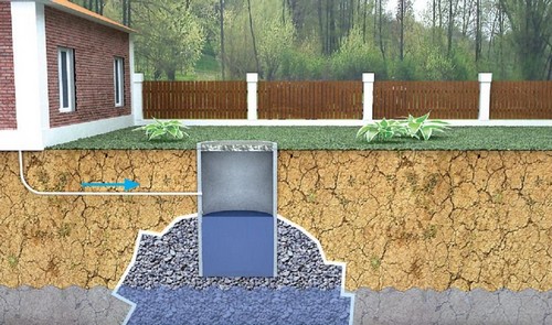
Dumping of untreated sewerage is strictly prohibited. For the disposal of wastewater in private homes, most often, septic tanks are installed. In these installations, effluent is settled and subjected to biological treatment. However, a conventional septic tank cannot provide a sufficiently high level of purification, so you have to additionally purify the water by installing an infiltrator for the septic tank.
An infiltrator or filter cassette is a device that receives water from a septic tank. The purpose of installing infiltrators is additional purification of the liquid. This post-treatment option is especially good for small areas where it is not possible to build large filtration fields. Consider what kind of device it is and how you can install it yourself.
Advantages
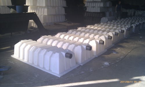
Can be used different variants devices for additional purification of water, which has already settled well in the septic tank. However, for private households, the most profitable option is the infiltrator. Outwardly, this device looks like a plastic box without a bottom. Its advantages:
- the possibility of removing wastewater to a shallow depth allows the use of soil post-treatment even with a shallow occurrence of soil water;
- the minimum weight of the plastic structure facilitates do-it-yourself installation;
- the ability to organize high-quality post-treatment for small area, so one infiltrator is able to replace 35 meters of drains in the filtration fields;
- the design copes well with the uneven flow of effluents;
- the affordable cost of the structure and the ability to install it yourself can reduce construction costs.
How does it work?
The process of water purification in the infiltrator proceeds as follows:
- well-settled water in septic tanks contains a minimum of foreign matter;
- through the pipe leading from the treatment plant, water enters the infiltrator, where it gradually seeps through the layer of rubble, finally being cleaned;
- due to the presence of ventilation, the water is not only mechanically filtered, but also biologically purified under the influence of aerobic microorganisms;
- the purified water is absorbed into the soil.
Advice! To make the infiltrator last longer, geofabric is used during installation. A layer of crushed stone is wrapped in geotextile, so soil particles do not contribute to its silting.
How to choose?
Before installing the infiltrator with your own hands, you need to choose the right model. In this case, it is necessary to take into account the performance and other characteristics of the equipment, as well as the cost of the equipment and the complexity of implementation. installation work. Experts recommend considering when choosing:
- One of the most important criteria is volume. The design for post-treatment should exceed the performance of the septic tank by at least three times. Only in this case, the post-treatment system will be able to work effectively during peak loads.
- An equally important selection criterion is the characteristics of the soil. The higher the permeability of the soil, the less infiltrators will be required to organize post-treatment with equal performance of the septic tank.
Advice! For example, for a septic tank, which cleans up to 0.6 liquid per day, if installed in sandy soil, it is sufficient to install one infiltrator with a capacity of 0.4 m³. If there is loam on the site, then the number of installations for post-treatment needs to be doubled, they are installed sequentially.
Most Popular Models
Today, there are different options for infiltrators on the market, the most popular models are:
- Triton-400;
- Polex-300.
Characteristics of the Triton model:
- total volume - 400 liters;
- overall dimensions 1.8 x 0.8 x 0.4 meters;
- weight - 15 kg.
Characteristics of the Polex model:
- total volume - 300 liters;
- overall dimensions - 1.22 x 0.8 x 0.51 meters;
- weight - 11 kg.
Installation
It is quite possible to install the infiltrator with your own hands. As a rule, the installation of a septic tank and a post-treatment device is carried out simultaneously, but it is possible to install infiltrators even after the installation of a local treatment plant is completed.
First of all, you need to choose the location of the local treatment plant, and the place is chosen not only for reasons of convenience, but also taking into account building and sanitary standards.
Advice! Despite the fact that the water that is absorbed into the soil is as free of impurities as possible, the post-treatment system should be located at the maximum distance from sources of drinking water. The minimum distance is determined by the permeability characteristics of the soil and ranges from 30 to 80 meters.
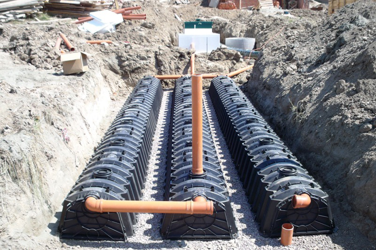
The infiltrator is located at a distance of 1-1.5 meters from the septic tank, the devices are connected by laying a pipe. Here are the basic installation rules:
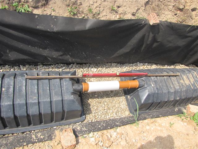
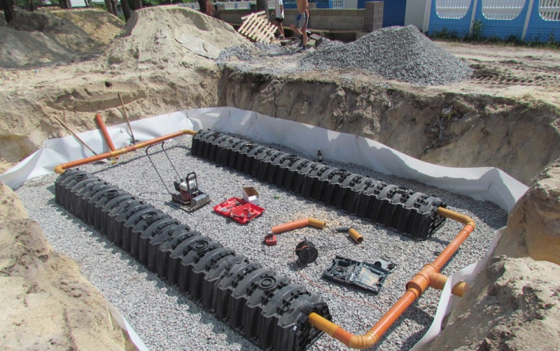
- First you need to prepare the pit. Its dimensions depend on the dimensions of the infiltrator, while the size of the pit should be half a meter greater than the length and width of the plastic container. The depth depends on how high the soil water rises.
- Next, you will need to proceed to the formation of the filter layer. It consists of crushed stone of medium fraction and river sand. To prevent rapid siltation filter layer, it is necessary to wrap the filter layer with geotextile. This is done as follows: the bottom of the pit is covered with geofabric so that the edges of the material protrude beyond the pit. Then crushed stone is poured in a layer of 50 cm, after which an infiltrator is installed, and the edges of the geotextile are lifted up and laid over a plastic container with an overlap.
- After installation, you need to check the correct installation with a level, since the liquid must move by gravity, the pipes must be laid with a slope.
- The inlet pipe is connected, as well as the installation ventilation pipe, all connections in the installation must be tight.
- Then, a layer of sand is poured over the plastic container and the geotextile layer, which is carefully compacted.
Correct installation is a guarantee of trouble-free operation of the local sewerage system. So, if the installation is performed with errors, then the infiltrator may emerge in the spring, destroying the entire post-treatment system.
So, the advantages of using infiltrators for post-treatment of wastewater are obvious. These devices provide environmental safety the use of septic tanks, at the same time, they take up little space and can be used even if soil water rises high enough on the site. At very high GWL it is possible to install an infiltrator on the surface of the earth, but in this case, the circuit will have to include a pump that will pump water from the septic tank to the infiltrator.
Water supply country house requires a mandatory sewerage system, that is, a system for the disposal and treatment of wastewater, which is formed as a result of the use of water for household needs and hygiene purposes (the so-called "grey" wastewater). Sewerage is also required for a flush toilet (water closet). Autonomous sewerage consists of three parts: - cleaning devices; - home network with plumbing fixtures; - yard network.
PURIFICATION FACILITIES
Task treatment facilities— reducing the amount of pollution in wastewater to such a level that it can be discharged into a reservoir or permeable soil without the risk of contamination of the latter. Decayable organic compounds contained in wastewater are converted into harmless inert substances during the treatment process. In addition, the number of pathogens is reduced many times (to an acceptable level). Thus, treated wastewater ceases to be a source of contamination. environment. However, the sanitary authorities (SES) require the disinfection of these waters when they are discharged into water bodies. Biological treatment is provided by bioagents - microorganisms and algae, for which sewage pollution is a source of nutrition and, as already mentioned, is converted into inert substances during the life of bioagents. Forced cleaning is performed in special installations where an environment with a high concentration of bioagents is created, which ensures intensive wastewater treatment. Such installations are due to high performance compact, but during operation they need energy costs - the process requires air supply. Therefore, they are not used in practice for local sewage systems, but natural cleaning systems are used. natural system wastewater treatment uses the self-cleaning ability of soil, soil. Cleaning is done in two stages. First, wastewater enters the so-called septic tank - a settling chamber, where they are clarified (precipitation of suspended particles). At the second stage, the actual biological treatment water - filtration.SEPTIC
A septic tank is a settling chamber in the form of a sealed well (round or rectangular). The volume of the well depends on the flow of wastewater. The permanently filled part of the well (hydraulic volume) should be equal to three times the daily inflow. If the flow of sewage does not exceed 1000 l / day, the septic tank is made single-chamber, if more - two-chamber (the first chamber is 3/4 of the total hydraulic volume). Under no circumstances should untreated sewage seep through the walls of the septic tank into the ground. Therefore, its design must be airtight: the walls are made of reinforced concrete, rubble stone (rubble concrete) OR red iron brick, the bottom is made of monolithic concrete or reinforced concrete slab. The construction technology is generally the same as for a shallow shaft well: the shaft is torn off to the full depth, about three meters, and lined. Walls made of rubble stone or brick are plastered with cement mortar (the ratio of cement and sand is 1: 3) and ironed (the wet surface is rubbed with cement). True, unlike the drinking well, as already mentioned, the bottom is pre-concreted here! The seam between the bottom and the wall is closed with a tide of cement mortar. In the case of using reinforced concrete rings, the design of a septic tank, designed for a house with a family of four to five people, looks something like that shown in Fig. 60.Rice. 60. Septic tank made of reinforced concrete elements (dimensions in mm): 1 - iron concrete ring diameter 1000 mm; 2 - wooden cover; 3 - reinforced concrete ring with a diameter of 700 mm; 4 - supporting reinforced concrete ring; 5 - cast-iron hatch (or wooden cover); 6 - ventilation riser; 7 - floor slab; 8 - plate-bottom; 9 - cement screed.
A mine is torn off with a depth of 3 m and a diameter of 1.5 m, a layer of crushed stone 100-150 mm is tamped at the bottom of it, then the bottom is poured monolithic concrete or stack reinforced concrete slab not less than 100 mm thick. Then two reinforced concrete rings are lowered one after the other (the rings must be firmly connected to each other, as shown in our book when describing mine wells) and seal the joints. As the concrete rings are installed, the space around them is covered with soil. If the groundwater level is high, reinforced concrete rings are coated on the outside with hot bitumen and the gap around them is filled with crumpled CLAY, carefully tamping it when laying. The thickness of the clay castle should be 250-300 mm. Inlet and outlet holes should be provided in the upper ring. Tees with a diameter of 100 mm are inserted into these holes. The transverse branch of the tee is passed through the holes to the outside and sealed. The inlet and outlet pipes of the same diameter laid in the trench are attached to it. The passage part of the tee, as can be seen from the figure, is oriented vertically. The lower end is immersed in waste water by 300 mm, the upper end rises above the water level. This design allows contaminants floating on the surface of the water to be retained and the inlet and outlet to be cleaned. The inlet should be 50-100 mm higher than the outlet, which is 300 mm from the top edge of the concrete ring. An overlap is arranged over the concrete ring. The easiest option is to close the septic tank with 60 mm thick boards or reinforced concrete tiles, then lay 2-3 layers of roofing material or waterproofing and cover it with slag or soil. If cleaning is necessary, such an overlap is easy to disassemble. But it is better to arrange a permanent hole - made of wood or concrete. In the first case, block the septic tank wooden shield with hatch 650 x 650 mm or x 700 mm. The hatch is covered with a lid. The walls of the shaft are sheathed with boards, and another overlap is arranged on top with top cover. The space between the covers is filled with insulation. In the second case, either a shaped reinforced concrete ring is used (conical with a lower diameter of 100 mm and an upper one under a standard cast-iron hatch), or, as in our figure, the well is blocked with a flat reinforced concrete ring with a hole with a diameter of 700 mm, and a reinforced concrete glass of the same diameter is installed on it and on top of it they arrange a hatch or a wooden cover. In order to provide access to the inlet and outlet tees, ventilation risers are fixed strictly above them - vertical pipe sections (cast iron, steel, asbestos-cement), which go to the surface of the earth and are closed with plugs. One of these pipes simultaneously plays the role of an exhaust. It is raised above ground level by 700-800 mm (that is, above the snow cover) and protected with a weather vane (a cap raised on stands above the upper cut of the riser). In a static state, in the absence of water inflow, the water level in the septic tank is set at the outlet mark. During the operation of the septic tank, the organic part of the sediment is gradually decomposed by microorganisms, therefore it is impossible to use bleach during operation and cleaning. The septic tank is cleaned once a year, and if the house does not have a flush toilet (water closet), then once every 2-3 years. The sediment is pumped out with a special submersible pump or a sewage truck (do not forget to provide access to the well when planning the site) late autumn at the beginning of frost (to avoid unpleasant odors). The septic tank is located at least 5 m from the house. If it is removed more than 15 m, it is necessary to arrange a manhole that provides access to the inlet pipe. Such a well is made of reinforced concrete rings with a diameter of 700 mm or in the form of a square pit 700 x 700 mm. With a high level of groundwater, it makes sense to reduce the depth of the septic tank well while increasing its diameter - for example, instead of two rings with a diameter of 1000 mm with a total height of 1800 mm, install one ring with a diameter of 2000 mm and a height of 1300 mm. Such a septic tank is made two-chamber: a vertical partition is installed along the entire height of the reinforced concrete ring. In this partition, two branch pipes with a diameter of 150 mm are provided: one, bypass, is placed 400 mm lower, and the second, ventilation, is 150 mm higher than the calculated water level.
FILTERING DEVICES
The design of the filter device must be selected depending on the type of soil and on the level of groundwater (see table 6).Table 6
TYPES OF FILTER DEVICES
(DIMENSIONS ARE GIVEN FOR DAILY CONSUMPTION UP TO 0.5 M3, THAT IS FOR A FAMILY 2 - 3 PEOPLE.)
| Soil type | groundwater level | ||
| - | Deep (below 3 m) | Medium (below 1.5m) | High |
| Sands (good permeability) | Filter well (diameter 1 m) | Underground filtration fields (irrigation network length 20-30 m) | - |
| Sandy loam: (good permeability) | Filter well (diameter 1.5 m) | Underground filtration fields (irrigation network length 30-50 m) | - |
| Loams and clays (weak permeability) | - | Sand and gravel filter with discharge of purified water into a reservoir (trench length 5 m; collector network area 2.5 x 2 m) | cassette (area 10-12 m 2 for loams and 15-8 m 2 for clays) |
| Clay (waterproof soil) | - | Filtration semi-buried sand and gravel embankment (area 5 m 2) | Filtering ground sand and gravel embankment (area 5-8 m 2) |
On sandy soils and sandy loams, a filtering well is arranged (when groundwater occurs at a depth of at least 3 m) or underground filtration fields (at a water level of 1.5–2 m). After passing through such a filter, wastewater seeps through the ground, where it undergoes additional treatment, to underground groundwater. So, if the conditions allow, that is, the soil has filtering properties (sandy or sandy loamy soils) and the groundwater is low, it makes sense to arrange a clarified wastewater filtration well next to the septic tank (settlement chamber). On poorly permeable and water-resistant soils, they arrange sand and gravel filters complete CLEANING, after which harmless water is discharged into a reservoir OR onto a relief. If the groundwater level is too high, the filter devices have to be raised higher and a pump used to lift the wastewater from the septic tank. The general scheme of local sewerage in this case looks like that shown in Fig. 61.
Rice. 61. Scheme of two-stage wastewater treatment with a filter well: 1 - a residential building with internal sewerage; 2 - well-septic tank; 3 - filter well; 4 - exhaust riser; 5 - sewage pipe.
As can be seen from the above diagram, the sewer pipe discharges wastewater from the house by gravity into the settling chamber (septic tank), from where they also enter the filter well by gravity. The filtered water seeps down to the groundwater. It should be noted that both the house fan pipe and both cleaning chambers are equipped with an exhaust hood to remove the formed in sewer system gases. A filter well, like a septic well, is a shaft about three meters deep, inside which a well is made of rubble stone, iron brick or reinforced concrete rings. The device of a filter well made of reinforced concrete rings with a diameter of 1500 mm is shown in fig. 62.
Rice. 62. Filtering well, mounted from reinforced concrete rings (dimensions in mm): 1 - water-breaking board; 2 - a manhole made of a reinforced concrete ring with a diameter of 700 mm; 3 - cast-iron hatch type "L"; 4 - wooden cover; 5 - support ring under the hatch; 6 - ventilation riser; 7 - floor slab; 8 - upper reinforced concrete ring; 9 - lower reinforced concrete ring; 10 - backfill; 11 - holes.
The shaft is dug out completely to a given depth. Its diameter should be 800-1000 mm larger diameter rings (see fig. 63). At the bottom, a concrete screed is arranged along a compacted contour in the form of a ring around the perimeter of the shaft, leaving open ground in the center, along the inner diameter of the concrete ring. Thus, the LOWER edge of the ring rests on concrete base, and the bottom of the chamber remains unconcreted and does not prevent sewage seepage.
Rice. 63. Mine of the filtering well (dimensions in mm): 1 - mine; 2 - well wall; 3 - holes with a diameter of 50 - 60 mm; 4 - concrete screed; 5 - open bottom of the well.
In the lower reinforced concrete ring, 80 holes with a diameter of 50-60 mm are drilled with a perforator with a horizontal and vertical step of 100-120 mm. If the ring is cast on its own, then easily removable plugs or nozzles for the holes are laid in the formwork in advance. IF the wall of the well is made of stones, gaps are left on the layer, and if it is made of brick, the masonry is made in half a brick (on the layer) in a checkerboard pattern, leaving gaps between adjacent bricks of 35-45 mm in each row. At a height of 1 meter, the well is covered with filter material (gravel, crushed stone, sintered slag, broken brick with a fragment size of 10–70 mm). Outside, between the walls of the shaft and the concrete rings, the same backfill is made. The inlet pipe enters the well through a hole in the concrete ring at a height of 1500 mm from the bottom of the well, that is, 500 mm above the level of the backfill, on which a water-breaking board is laid at the point where the jet falls (to prevent soil erosion). The board must be fixed, for example, with two pins going into the backfill. The branch pipe should not be cut flush with the wall, it is better to leave the outlet inside the well 50-80 mm - otherwise the water will flow down the wall and erode the backfill. The working volume of the well is covered from above with a flat reinforced concrete ring with holes for the cover (500 mm in diameter) and for an exhaust riser with a diameter of 100 mm. A reinforced concrete ring is installed on the ceiling - a hole with a diameter of 700 mm, and its top is closed with a hatch or a wooden cover. A standard reinforced concrete ring is placed under the cast-iron hatch. The exhaust riser with a wind vane must rise above ground level by at least 700 mm. In severe frosts (from minus 25 ° C), the bottom cover is insulated. Now you should deal with the diameter of the working chamber of the filter well. The volume of the filter, and hence its performance, depends on this diameter. Wastewater leaves both through the bottom and through the perforated side wall well. Sand passes water better than sandy loam. "Grey" household water seeps through more easily than water from a water closet. The dimensions of the well at various wastewater flow rates, taking into account the factors we have listed, are given below in table 7.
Table 7
WELL DIAMETER AT FILTER HEIGHT 1 M DEPENDING ON SOIL TYPE
When constructing a square well, you can take the side of the square, equal to the diameter indicated in the table. Wastewater treatment in filter wells takes place in a biofilm - a thin layer formed by microorganisms on the surface of filter granules. for these microorganisms, organic matter in wastewater is a nutrient medium. The final treatment of wastewater occurs in the soil layer through which it infiltrates before reaching the groundwater. Underground filtration fields are used, like filter wells, in sandy and sandy loamy soils. The device of a filtering well is possible, as was said, in the case when the groundwater lies at a depth of at least 3 m. If this depth is 2 or last resort 1.5 m, it is necessary to build a filter of a different design - in the form of an extensive network of filtering trenches. This system is cheaper and easier to build, besides, it provides irrigation of the site. The only difficulty is that the underground filtration fields must be laid in advance, before the site is built. The device of the underground filtering network is shown in fig. 64.
Rice. 64. Fields of underground filtration: 1 - septic tank; 2 - dosing chamber; 3 - distribution pipeline; 4 - distribution wells; 5 - irrigation pipes; 6 - ventilation risers with a wind vane.
The dosing chamber, arranged at the outlet of the septic tank, provides the underground filtration fields with a uniform influx of wastewater. It is a container with a diameter of 1000 mm (or an area of 1000 x 1000 mm) with a siphon located inside, which periodically self-charges and self-discharges clarified sewage coming from the septic tank. Siphon diameter - 100 mm, elbow height - 200 mm. The distribution pipeline is a pipe with a diameter of 100-125 mm (plastic, asbestos-cement or ceramic). It is laid in a trench at the outlet depth of the dosing chamber with a slope of 0.02 (2 cm per meter of length), which ensures the gravity flow of wastewater. In any case, the distance from the pipe to the ground must be at least 500 mm (Fig. 65).
Rice. 65. Laying a distribution pipeline for underground filtration fields: 1 - pipe Zh 100 - 125 mm; 2 - lining (brick must be laid every 0.5 m); 3 - trench
A distribution well is arranged at branching points - where filtration trenches with irrigation pipes laid in them depart from the distribution pipeline. A well with a diameter of 500-700 mm is laid out of red iron brick or a reinforced concrete ring is used. At the base of the well arrange cement screed on compacted gravel, trays are placed above the screed at a level corresponding to the trays of the distribution and irrigation pipes (see Fig. 66). This level is different for each well, since the distribution pipeline is laid with a slope. From above, the well is covered with a wooden lid (shield) and covered with gravel, crushed stone or slag (granule size 15-25 mm).
Rice. 66. Distribution well of underground filtration fields: 1 - concrete base; 2 - distribution pipeline; 3 - concrete ring; 4 - wooden cover; 5 - input of an irrigation pipe.
By installing plugs in the well, it is possible to cut off certain branches from the network and thereby regulate the irrigation of zones personal plot. Filtration trenches with irrigation pipes are laid in parallel rows at a distance of at least 1.5 m in sandy soils and 2.5 m in sandy loam. The total length of trenches required for wastewater disposal is given below.
Table 8
TOTAL LENGTH OF FILTER TRENCHES
| Waste water quantity | climate band | |||||
| South | Medium | Northern | ||||
| For gray wastewater | ||||||
| 0.5 mz/day (2-3 people) | 14 m | 18 m | 21m | |||
| 1.0 m3/day (4-5 people) | 28 m | 35 m | 42 m | |||
| During operation of the water closet | ||||||
| 0.5 m3/day (2-3 people) | 20 m | 25 m | 30 m | |||
| 1.0 m3/day (4-5 people) | 40 m | 50 m | 60 m | |||
Each trench branching from the distribution pipeline must be no longer than 20 m. The depth of the trench is selected depending on the calculated value of the minimum winter temperature.
Table 9
DEPENDENCE OF TRENCH DEPTH ON TEMPERATURE
Temperature, °C Trench depth, m
200,7
301,0
401,5
<401,8
At the bottom of the trench, a groove 300 mm wide and 200 mm deep is torn off, into which a filter layer made of gravel, crushed stone or slag (granule size 15–25 mm) is laid, on which an irrigation pipe is laid. The irrigation pipe should have a slope of 0.02 away from the well for gravity flow of sewage and holes through which water irrigates the filter layer. You can use asbestos-cement, plastic or ceramic drainage pipe with a diameter of 75-100 mm. If an asbestos-cement pipe is used, spout holes are arranged in it in the form of cuts for a third of the diameter 10 mm wide in 150 mm increments and laid with cuts down.
Rice. 67. Irrigation pipe made of asbestos cement (a), plastic (b) and in the form of a brick tray (c, d): 1 - pipe; 2 - cuts or holes (when laid in a trench, they face down); 3 - brick side of the tray; 4 - brick bottom of the tray; 5 - gap 15 - 20 mm; 6 - filter layer.
Two rows of holes with a diameter of 10 mm are drilled in a plastic pipe in a checkerboard pattern at a distance of 50 mm from each other (Fig. 67 b). Pottery drainage pipes are not laid end-to-end, but leaving a gap of 15 mm, which is covered from above with roofing felt overlays. Instead of irrigation pipes, a brick tray with a section of 120 x 120 mm can be laid along the filtering layer, leaving gaps of 15-20 mm at the bottom of the tray (see Fig. 67 c). As shown in fig. 64, at the ends of the filter trenches, or rather, irrigation pipes, exhaust risers should be provided. They are made from a pipe with a diameter of 100 mm, a height of 0.5-0.7 m, and are covered with a wind vane from above. Underground filtration fields can be built without collector wells. In this case, the sections of the distribution pipe with a diameter of 150 MM are connected by means of tees facing down, to which, through a square, the irrigation pipes are connected in a checkerboard pattern. For elbows and tees, cast iron sewer fittings are suitable (see Fig. 68).
Rice. 68. Underground filtration network with irrigation pipes connected using tees: 1 - septic tank; 2 - dosing chamber; 3 - collector pipe (with one distribution well); 4 - tee; 5 - irrigation pipe; 6 - hood; 7 - square.
FILTERING DEVICES FOR WATERPROOF OR SLIGHTLY PERMEABLE SOILS
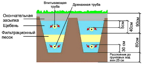
In the event that the soil in your suburban area is such that the soil does not pass water well, the filter design has to be complicated. the fact is that when the waters go into sandy or sandy loamy soil, they are additionally filtered, seeping into the groundwater. Therefore, on impervious soils, care must be taken to ensure that the wastewater is sufficiently purified already at the outlet of the filter - it is not necessary to rely on filtration in the soil. Such a filter is made in the form of a three-layer cake: on top - a network of irrigation pipes, below - a network of drainage pipes repeating its contours, and between them - a meter-thick filtering sand and gravel filling. The irrigation network distributes the wastewater over the entire area of the filter bed, and the drainage pipes collect the filtered water. Structurally, such sand and gravel filters are arranged either in the form of a network (collector with transverse pipes) or in the form of a long trench. The choice depends on the configuration of suitable unoccupied areas on the site. A linear sand and gravel filter is arranged in the form of a trench with a depth of about 3 m and a width of 0.5 m. The bottom of the trench should be approximately 1.5 m below the septic tank outlet or dosing chamber. granules 15-30 mm. A drainage pipe is laid on it from asbestos-cement or plastic pipes with a diameter of 100 mm with side water intake windows. In asbestos-cement pipes, such windows are cuts 10 mm wide with a depth of 20 mm and with a step of 100 mm, and in plastic pipes - holes with a diameter of 10 mm with a step of 100 mm. The cuts and holes on both sides of the pipe are staggered (Fig. 69).Rice. 69. Design of windows in drainage pipes (dimensions in mm): a - asbestos-cement pipe; b - plastic pipe.
The drainage pipe is covered with a large fraction of crushed stone, gravel or slag (15-30 mm), overlapping the top of the pipe by 50 mm, a 100-mm layer of medium fraction (5-15 mm) is poured on top, and a layer of fine fraction (2-5 mm) is poured on top of it. ) of the same thickness (100 mm). A meter layer of sand (coarse and medium-grained) is poured over the rubble. Crushed stone (gravel, slag) of a large fraction (15-30 MM) is again laid out over the sand, and an irrigation pipe is already laid on it, arranged similarly to a drainage pipe, but with windows oriented downwards (see Fig. 67 a, b). This pipe is covered with the same backfill of a large fraction (50 mm above the top of the pipe). It remains to cover the backfill with a layer of roofing material or hydroisol and cover it with soil, having previously installed exhaust risers (from a 100-mm asbestos-cement pipe, rising 0.5-0.7 m above the ground and covered with a weather vane). The hood should be installed at the beginning of the drainage and at the end of the irrigation pipes (in the direction of wastewater flow). The cross section of the filter trench is shown in fig. 70.
Rice. 70. Cross section of the filtering trench (dimensions in mm): 1 - drainage pipe; 2 - coarse-grained backfill; 3 - medium-grained backfill; 4 - fine-grained backfill; 5 - layer of sand; 6 - irrigation pipe; 7 - coarse-grained backfill; 8 - waterproofing; 9 - soil; 10 - exhaust riser.
The length of the filtering trench depends on the volume of wastewater and is 100 l / day per 1 meter of pipe (for "grey" waters - 150 l / day), for example, 5 m for a flow rate of 0.5 m3 / day (2-3 people) and 10 m for a consumption of 1 m3/day (4-5 people).
Disinfection and wastewater disposal
The purified water, since it does not go into the ground, has to be further diverted to the receiving reservoir or to the relief (ravines, drainage ditches, and so on). This water no longer poses any danger as a source of infection.Table 10
RESIDUAL TOTAL CONTENT OF BIOLOGICAL IMPURITIES IN WASTEWATER AFTER CLEANING WITH A SAND AND GRAVEL FILTER
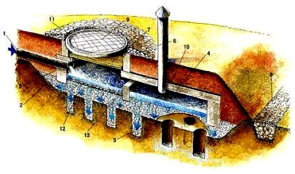
However, usually sanitary and water authorities require additional disinfection of water by chlorination. For this purpose, before the release of wastewater, a small well with a diameter of 0.5 m is arranged. The depth of the well is about 3 meters. Its bottom should be 0.5 m below the trays of the inlet and outlet pipes, while the volume of water will be about 100 liters. At the bottom of the well, a cement screed is laid on compacted rubble, reinforced concrete rings serve as walls. From above, the well is covered with a lid or hatch. One chlorine cartridge lowered into such a well provides water disinfection for a month. It must be taken into account that the constant discharge of water with a residual chlorine content into the reservoir can harm aquatic vegetation, fish and microorganisms. Therefore, in agreement with the sanitary protection authorities, chlorination of wastewater is carried out only in conditions of increased epidemiological danger, about which these authorities warn the population. On fig. 71 shows a scheme for discharging wastewater along the chain: filtering ditch - disinfection well - discharge to the relief. The clarified wastewater from the septic tank or dosing chamber enters the irrigation pipe, seeps through the layers of filtering backfill and is collected by the drainage pipe. Then it enters the disinfection well, where it is disinfected and discharged into a reservoir or onto a relief. When water is discharged onto a relief (into a ravine or ditch), a stone backfill is arranged at the point where the jet falls so that the soil in this place does not erode.
Rice. 71. Scheme of wastewater treatment on waterproof soils: 1 - irrigation pipe; 2 - filter layers of crushed stone and sand; 3 - soil; 4 - drainage pipe; 5 - ventilation risers; 6 - disinfection well; 7 - chlorine cartridge; 8 - discharge pipe; 9 - stone fill.
If for some reason it is difficult to place a long filter trench on the site, a more compact collector-type sand and gravel filter can be arranged. In this case, both the drainage and irrigation networks are arranged like miniature underground filtration fields - in the form of a horizontal distribution pipe and branch pipes with holes extending from it in both directions. For example, to filter 1 m3/day (5-6 people), the filter pit should have dimensions: length 2.5 m (this is the length of the collector) and width 2 m (to place meter-long working nozzles on both sides of the collector; see Fig. .71). The bottom of the pit is located approximately 1.5 m below the tray of the outlet pipe of the septic tank (or dosing chamber). The bottom has a slope to the central part equal to 0.03. As with the installation of a filtering trench, a backfill (gravel, crushed stone or boiler slag) of a large fraction (15-30 mm) is laid at the bottom of the pit, and a drainage network consisting of a collector pipe and 5 pairs of meter-long drainage pipes extending from it . The design of nozzles made of asbestos-cement or plastic pipes is visible from fig. 73. Branch pipes are connected to the collector using cast iron sewer crosses. The distance between the drainage pipes is 500 mm. The holes in them are oriented to the sides during assembly. The drainage network is covered with the same fraction of crushed stone 50 mm above the top of the pipes, then with two layers - medium (5-15 mm) and fine (2-5 mm) fractions - 100 mm high and a meter layer of coarse and medium-grained sand. Then, as in the case of a filter trench, an irrigation network is assembled exactly above the drainage network, consisting of a collector pipe, cast-iron crosses AND irrigation nozzles (see Fig. 72), orienting them with holes down. The irrigation network, connected by a collector to the outlet of the septic tank (dosing chamber), is covered from above with a coarse-grained fraction, blocking the pipes by 50 mm, then covered with roofing material or hydroisol and covered with soil. At the end of the irrigation and at the beginning of the drainage collectors, ventilation risers are installed from an asbestos-cement pipe with a weather vane, bringing them 0.5–0.7 m above the ground (so that snow does not fall asleep in winter).
Rice. 72. Collector sand and gravel filter (dimensions in mm): 1 - upper (irrigation) collector; 2 - cast-iron sewer crosses; 3 - ten irrigation pipes (asbestos-cement or plastic); 4 - drainage manifold pipe; 5 - ten drainage pipes; 6 - to the vent, riser.
Ground filters
The biggest problems arise when the high water table prevents the filter from being buried in the ground. At first glance, this is incomprehensible: why not arrange the same structure on the surface? Here's the thing: as you can see from what was said earlier, the entire sewerage system - from plumbing fixtures in the house to the septic tank and filters - works on the principle of sewage gravity about 1.5 m below the surface of the earth. And at the same level, as already mentioned, there is a collector or input of an irrigation system in any of the filters described above, whether it is a filtering well and underground filtration fields on permeable soils or a filtering trench or a distributed sand and gravel filter. And because the system has no moving parts other than the flow of water, it needs little to no maintenance other than the annual septic tank cleaning. If it is necessary to arrange a ground or semi-submerged filter, then the input of the irrigation pipe is higher than the outlet of the septic tank or dosing chamber, and this problem has to be solved by raising the wastewater to a higher level by means of a pump. Such a system automatically becomes less reliable, it depends on the availability of electricity, and so on. The inconvenience is, of course, the need to place a rather bulky structure on the site - a ground sand and gravel filter. Of course, the first problem can be circumvented if you raise the entire previous part of the system: arrange a ground septic tank, raise and insulate sewer pipes, and place all plumbing in the house only on the second floor. The idea, as they say, is interesting, but as a result, instead of a country house, we will get a cottage adjacent to a processing factory ... Of course, this has its own charm. But you can not fence the garden, but pump wastewater with a special pump.filter cassette
If the soil is at least slightly permeable, then a filter cassette is arranged through which the filtered water will go into the soil. If the soil is impermeable, then a filter embankment is necessary, followed by the discharge of water into a reservoir or onto a relief. The filter cassette can operate at a soil filtration coefficient of at least 0.03 m3/day. This figure means that if you dig a pit with an area of 0.7-1 m2 in the ground, pour water into it and cover it with a waterproofing lid, then the water level will drop by 3 cm per day. You have to pay for the low water permeability of the soil by increasing the filter area. Structurally, the filter cassette is a shallow pool of a rather large (as can be seen from the table) area, at the bottom of which a filtering layer of crushed stone is laid. From above, the pool has a ceiling, protected by a layer of waterproofing and insulated with a layer of soil. Water is supplied to the pool by a pump, spills over the filter layer, gradually leaves it and seeps through the loam to groundwater.Table 11
FILTER AREA
It is easy to estimate the basin area based on the soil filtration coefficient. If for loams this coefficient is equal to 0.05 (from 1 m2 50 l of water per day goes into the soil), then to receive 500 l (a family of 2-3 people) an area of 10 m2 will be needed, and for 1 thousand l (4 -6 people) - 20 m2. for clay soils with a filtration coefficient of 0.03, the corresponding areas will be approximately 17 and 34 m2. It should be taken into account that the actual soil filtration coefficient may differ slightly from the average calculated value. When constructing a filter cassette, they first arrange a flat area at a mark above the groundwater level, that is, either a shallow pit is torn off, or soil is poured to the desired level. Then the site is covered with a filter layer (gravel, crushed stone or slag of medium and fine fraction, that is, with a grain size of 2-10 mm), first to a height of 100 mm. Then, supports are installed on the gravel under the ceiling in the form of columns made of iron brick or reinforced concrete foundation blocks 400 mm high. The columns are installed in parallel rows along the long side of the site, with a gap between them of 15-20 mm for the inner rows. The distance between the rows is 1 m FOR overlapping on wooden beams (poles with a diameter of 8-10 cm) and 3 m for reinforced concrete slabs (suitable and defective). After installing the columns, the filter layer is finally filled up, with a total thickness of 200 mm. Recommended site sizes for the filter cassette are shown below (Table 12), although, of course, you can choose any convenient site configuration based on the layout of the site.
Table 12
FILTER CARTRIDGE AREA FOR DIFFERENT SOILS
| Cassette area | Wastewater consumption, m3/day | Length, m | Width, m | Number of rows of supports |
| 12 m (loam) | 0,5 | 4 | 3 | 4 |
| 18 m2 (clay) | 0,5 | 6 | 3 | 4 |
| 24 m2 (loam) | 1,0 | 8 | 3 | 4 |
| 6 | 4 | 5 | ||
| 36 m2 (clay) | 1,0 | 12 | 3 | 4 |
Floor poles should be sanded and laid in the form of a roll, close to each other. A layer of slag 0.15–0.2 m high is poured over the poles or reinforced concrete slabs, rolled waterproofing is laid and an insulating layer of soil 0.5–0.8 m high is poured. 73.
Rice. 73. The device of the filter cassette (dimensions in mm): 1 - sewage supply pipeline (from the pump); 2— filtering backfill; 3 - support blocks; 4 - drainage tray around the embankment; 5 - wooden cover; 6 - jet screed of columns installed with a gap of 15 - 20 mm; 7 - ventilation riser; 8 - overlap; 9 - filter wells.
The part of the pool where the sewage supply pipe exits is separated by a transverse jet wall with slots, which forms a water distribution chamber that ensures uniform distribution of water across the width of the channel. Above the supply pipe in the ceiling, a wooden cover (0.5-0.7 m in diameter) is arranged, protected from above by waterproofing. As can be seen from the figure, the entire device is equipped with a ventilation riser (asbestos-cement pipe with a diameter of 100 mm) with a wind vane at the top, rising 0.5–0.7 m above the cassette. A drainage tray 200 mm wide and 300 mm deep is arranged around the embankment to drain precipitation. Ground filters have to be installed on water-resistant and semi-permeable soils with a high level of groundwater. This is the most unfavorable situation, and therefore the cleaning system is the most complex. One of the options for a filter placed above the natural relief marks is a filter mound. It is used in clay soils, with a high level of groundwater. Drainage pipes must be located at least 1 m above the sewage; and the height of the filtering layer, as we have seen, is 1 m. These two conditions determine whether the filter will be partially buried in the ground or whether its base will fall on the zero mark of the relief. The device of a bulk filter is no different from the device of a filter trench or a collector filter described above, but since the entire system (drainage, sand and gravel backfill, irrigation network) is partially or completely above the ground, the wall of the above-ground part of the filter is an earth embankment.
PUMPING OF WASTEWATER
If it is required to supply wastewater to the irrigation pipe of the filtering device, it is necessary to install a pump after the septic tank or dosing chamber. Since the water is already clarified, you can use a conventional water pump, centrifugal or submersible. The pump can be installed: - in a special small well (metal or reinforced concrete), designed for a water capacity of 40-60 liters and equipped with a counter electric sensor (for example, type PM - 51), which ensures that the pump is periodically turned on and sewage is supplied to the filter in volley portions. When using paging, a dosing chamber is not needed; - in the second chamber of a two-chamber septic tank. A centrifugal pump can be installed on the floor of the septic tank. At the end of the suction pipe, a mesh filter (mesh 1 mm) on a metal frame should be installed. It is better to place the submersible pump entirely in a frame tightened with a filter mesh. Sometimes it is advisable to install a pumping unit for pumping completely treated wastewater (after the filter). For example, you can use it to water plants. The need for pumping wastewater may also arise when they are discharged after cleaning on a filtering device, if the relief does not provide gravity. In winter, such purified water can be pumped to the surface of a frozen reservoir for freezing. Such a pumping unit requires a much larger volume of the storage chamber - 3-3.5 m3 and is structurally designed as a septic tank, only without an outlet pipe and with a pump. the bottom of the chamber must be made with a slope of 0.1 to the location of the submersible pump or the intake pipe of the centrifugal pump. The water level must be maintained 100 mm below the inlet pipe tray. The centrifugal pump is installed on a console attached to the wall of the well, and the intake pipe is equipped with a strainer (1 mm cell). The submersible pump is hung on a chain or cable below the water level, and a basket-shaped filter is placed at the inlet of wastewater into the well tank. The well is equipped with a ventilation riser and a float level sensor with a rod, the upper end of which shows the water level and allows you to judge the overflow and the need to pump water,HOUSE NETWORK
The task of the internal sewer network is to collect and deliver wastewater from all plumbing fixtures to the street pipeline. Washbasins, kitchen sinks, washing machines, bathtubs, shower cabins, etc. are connected to fan risers (or risers) with a diameter of 50 mm. The connection from the device to the riser is carried out with a fan pipe of the same diameter with a slope of at least 0.025 (25 mm per meter). At the outlet of these devices, a water seal is installed (usually in the form of a siphon), which prevents the penetration of odors and gases from the sewer network into the room. A toilet bowl with a flush cistern (water closet) is connected to a 100 mm diameter fan riser. The eyeliner is carried out by a fan pipe with a diameter of 100 mm with a slope of not more than 0.012 (12 mm per meter). Note that the sewer pipe from the toilet must pass either with the specified slope or vertically. This slope is chosen in such a way that the wastewater fills the pipe along the entire length and carries away dense fractions. An unjustified increase in the slope will lead to blockage - the water will drain too quickly, not having time to fill the pipe and wash off the dense fractions that will settle on the pipe walls. Regardless of the presence of a water closet, one riser in the house must have a diameter of at least 100 mm. This riser is designed for ventilation of the network and prevents the failure of water seals. If the layout of the premises allows, all plumbing fixtures can be connected to this riser. All sewer risers communicate with a collection sewer pipe, which removes wastewater from the house. It is best to lay it under the floor of the first floor (but it is also possible along the floor, along the wall). The collection pipeline must have a diameter of 100 mm, it is also laid with a slope of 0.012 (12 mm per meter) towards the outlet from the house. The ventilation riser should be located as close as possible to the highest point of the collection pipe and at the same time close to the chimney or heating riser. This will improve traction. The ventilation stack must be led 700 mm above the roof and equipped with a deflector. Its upper part, which is located outside the heated premises, must have a diameter of 150 mm. All risers at a height of 800-1000 mm from the floor on each floor are equipped with a revision (cleaning hatch). The outlet of the pipeline from the house also has a diameter of 100 mm. A window of 300 x 300 mm is provided in the foundation of the house or in the basement wall, the outlet pipe is laid in it so that the gap above it is at least 150 mm - otherwise the pipe may break when the house settles. The holes are sealed with clay concrete (a mixture of crumpled clay with crushed stone). If the house has a waterproofed basement (protected from a high level of groundwater), the outlet window is arranged in the form of a metal sleeve with a diameter of at least 250 mm and the gap is sealed with a cable (tarred strand) packing. The sewer house network is laid with cast-iron or plastic pipes with a socket at one end, using fittings (shaped parts) for connections. Cast iron products in the joints are caulked with a cable or linen strand and minted with a wet cement mortar. In plastic products, seals are provided with rubber rings (or others, depending on the type of pipe).YARD NETWORK
The yard network is a system of sewer pipes connecting the outlet from the house with a treatment plant - a septic tank, a dosing chamber, a filter device, and so on. You can use cast-iron or plastic socket sewer pipes or asbestos-cement non-pressure pipes. The joints of the pipes are connected as follows: - For cast-iron pipes - they are caulked with a cable or a tarred strand and caulked with a wet cement mortar; - for plastic pipes, a crimp rubber ring is provided in the socket, which provides the necessary sealing; - for asbestos-cement non-pressure pipes, asbestos-cement couplings with a rubber seal are used. As has been repeatedly said, the pipes through which wastewater moves must have a slope (decrease in the direction of travel) that ensures their gravity flow. The slope should ensure that the pipe is lowered by 2 cm with each meter, but if this is not possible, at least 1.5 cm per meter. You should especially beware of areas with a reverse slope - they lead to the appearance of pockets, where blockages are most often formed and where stagnant water remains, which freezes in winter, blocking or narrowing the pipe section. For laying pipes, a trench is torn off below the depth of soil freezing, which is approximately: - 0.7 m - in the southern regions; - 0.9-1.2 m - in the middle lane; - 1.5-1.8 m - in the northern regions of Russia. If, when digging a trench, damaged areas are found in the soil, this soil is selected, sand is added and thoroughly tamped when wet. In limestone and other fragile soils, a sand cushion 150 mm high is poured into the bottom of the trench. After laying the pipeline, it is desirable to first cover it with sand 100 mm above the top of the pipe with tamping of the sinuses on both sides of the pipe, then the trench is covered with local soil, tamping each layer. It is advisable to lay a trench without turns. If the layout of the site does not allow this, manholes must be provided at the turning points (the angle of rotation should not be sharp, i.e., less than 90 °). A manhole is also arranged at the entrance to the septic tank, if it is more than 8 m away from the house. The depth of the manhole is determined by the depth of the sewer pipeline. Its diameter at a depth of up to 1.2 m should be at least 700 mm, at a greater depth - 1000 mm in the working part, and above it - an overlap and a cylindrical manhole with a diameter of 700 mm. You can arrange a manhole in the form of an oblique cone, laying it out of brick or using an appropriate reinforced concrete ring (the wall of the manhole must be vertical under the hatch). The manhole must be airtight, so the seams between the reinforced concrete rings are sealed with cement mortar and rubbed. If the wall of the well is laid out of red iron brick (in half a brick in dry soils, in a brick in the presence of groundwater or with a depth of the working part of the well more than 2 m) on cement mortar, the seams are also rubbed from the inside. The walls of the well are installed on a concrete screed of class B 7.5. The screed is located at the depth of the pipe, for which a tray is arranged in it (in a rotary well - rounded) with a radius of 300 mm. The pipe inlets into the well are closed with a cable and a wet solution to ensure tightness. In the presence of groundwater, the outer surface of the well should be coated with hot bitumen. The manhole of the well is covered with a cast-iron circle (lid).A facility for collecting and treating wastewater is a necessary element of local sewage. Buying a finished structure is not always affordable for the budget, so a do-it-yourself septic tank has become a worthy replacement for a factory tank.
Advantages of septic tanks
Country plots are equipped with two types of autonomous sewage: a cesspool or a septic tank. The first option attracts with ease of execution and low price. Pits are an acceptable way to dispose of wastewater if there are few of them and sewers are rarely used. In other cases, this method turns into soil pollution on the site. Replacing the drain pit with a septic tank for a country house provides undeniable advantages:
- Environmental Safety. The construction allows not only to accumulate waste, but also to clean it to an acceptable level.
- Maintenance economy. The operation of the pit requires frequent access to the sewers for pumping sewage. The design of the septic tank allows you to order the service no more than once a year, and the installation of a biological station completely eliminates pumping.
- Lack of smell. The tightness of the structure and the processing of waste by bacteria make it possible to forget about the unpleasant smell of sewage.
- Durability. The building is designed for decades of operation. This period is due to the durable materials used in the manufacture and features of operation.
How to calculate the optimal volume of a septic tank
The performance of the facility is calculated according to the norms of water consumption per person. The average value taken as the basis for the calculation is 200 liters. This more indicative displays the real picture, if the owners do not use a large number of plumbing fixtures, then a reduction factor of 0.8 can be applied. With active water consumption, the average indicator is recommended to be increased by 1.5-2 times.
When calculating a septic tank, it is necessary to multiply the total volume of effluents per day by 3. This is the period allotted for settling waste. Simple calculations allow you to reduce the performance table of the treatment plant.
These calculations are approximate, for a more accurate value, you must consider:
- drain temperature;
- stock for the appearance of guests and additional plumbing.
Volume distribution by chambers
High-quality wastewater treatment requires the use of several cameras. With a water consumption of about 5 m3, a two-chamber septic tank is sufficient, with a flow rate of 10 m3, three cameras must be installed. In the manufacture of two chambers, the first occupies 75% of the volume, in the three-chamber model the first - 50%, the other two each 25% of the total volume. The device of wells made of concrete rings allows the same size for all chambers.
The installation depth of the septic tank depends on the level of groundwater (GWL), if they are close to the surface, then buried models will have to be abandoned. The effective installation volume in this case is achieved by horizontal dimensions.
Groundwater is close, what to do?
Planning the placement of engineering communications includes studying the plan of the area and the level of groundwater. When the GWL is located less than a meter, problems with making a septic tank with your own hands for a private house will begin in the process of digging a foundation pit. If water is constantly collected in the pit, it must be pumped out with a pump, with a quick filling, you will first have to arrange a drainage system.
Drainage sewerage on site
A high water level threatens not only the flooding of the septic tank, but also other buildings. To reduce the GWL, an annular drainage sewage system is installed, passing through the entire site. The technology of its device is as follows:
- Along the perimeter of the site, trenches are dug, on the bottom of which crushed stone and sand are poured.
- The rock layer is covered with geotextile. Large washed gravel is poured on it and perforated pipes are laid, covering with the same canvas.
- Rotary wells are installed at the intersections of pipes. The trenches are sloped and the water seeping into the pipes moves by gravity.
- From the wells, the liquid enters the storage tank with a filling sensor. When it is triggered, the pump turns on and discharges water into a special pool or simply into the nearest body of water.
Materials for the manufacture of a septic tank on a site with a high GWL
Water from the soil will seep into a leaky structure made of car tires or concrete wells, so the following is used for structures:
- polymer container;
- reinforced concrete monolithic tank.
Advice. With a close location of water, a plastic storage septic tank is installed for giving, if the use of sewage is rare, its volume will last for a year.
When using a sealed plastic tank, the pit is dug 20-25 cm larger than its size. At the bottom of the pit, a pillow of sand is poured to a height of 10 cm and a concrete screed is poured. The container is attached to the frozen slab with cables, this will avoid ascent. The tank body is backfilled with a 5:1 mixture of sand and cement, this will prevent the septic tank from moving.
A monolithic concrete structure, the best answer to the question of how to make a septic tank if groundwater is close. The structure is durable and tight, after applying waterproofing it is not threatened by the penetration of liquid from the outside. Filtration fields are usually arranged for post-treatment of wastewater from, but with a high GWL, a special scheme should be applied.
Ground filter cassette
The water purified in the septic tank enters the well, from which it is pumped into the filter cartridge. Her device is as follows:
- A layer of earth is removed to a depth of 40 cm. It is replaced with sand and the resulting platform is rammed.
- A fence of concrete blocks is installed around the perimeter and covered with rubble.
- A plastic container made without a bottom is installed on the rock layer, a pipe from the well is connected to it.
- The structure is equipped with a ventilation pipe and is first covered with expanded clay, and on top with a layer of 25 cm of earth. This is the ground filter cassette.
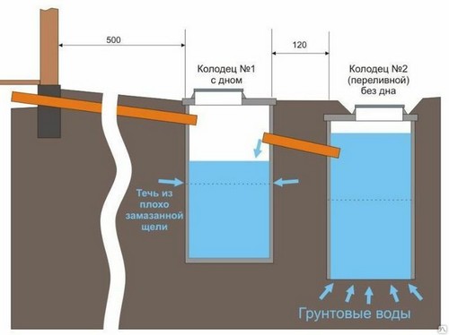
The installation scheme of a septic tank at a high GWL
Septic tank models: strengths and weaknesses
When choosing a treatment plant model for their site, owners are looking for a compromise between labor and cost reduction and efficient operation. An unequivocal recommendation on how to properly make a septic tank in a private house will be the installation of several cameras. But all options are worth considering.
Single chamber septic tank
A model consisting of one cell is not suitable for permanent residence. This design is suitable for a site with periodic visits. Usually it is a buried sealed container. But there are facilities built with a filter layer and discharge into the soil. Such wells are made of concrete rings, biological preparations are added to them to improve the quality of cleaning. The construction requires pumping out with cesspools, although the need rarely arises.
 single chamber septic tank
Double chamber model
The chambers of the structure are made of durable material that is not susceptible to the aggressive effects of waste and soil pressure. For this use:
- brick, the laying of which is cement mortar;
- plastic tanks;
- reinforced concrete rings with and without bottom;
- monolithic concrete.
A pit for a septic tank is dug 5 m from the house and 30 from the well. Its dimensions depend on the dimensions of the chambers. When using concrete rings, space is left for placing a person in the process of waterproofing the structure. Sewer drains are supplied by a pipeline placed in a ditch with a depth of 1 meter. The pipe is located with a slope towards the septic tank, this allows the liquid to move by gravity.
The two-chamber structure works according to the following principle:
The first section or well is made with sealed walls and a bottom. Drains enter it and settle for three days, until medium-sized frock coats settle to the bottom, the water overflows into the next section. Anaerobic bacteria are involved in the process of sludge decomposition.
The second chamber has no bottom, but a filter layer of sand and gravel is poured into it. Partially purified water is discharged through this layer into the soil. A more complex method of water disposal is also being arranged - through drainage pipes laid on filtration fields.
 Two-chamber sump
Advice. The design of two chambers is the best option for a septic tank for a bath. If there is no toilet in the building, then you can stop at a single-chamber model.
Three-chamber sump
It is better to carry out work on the installation of a treatment plant in parallel with the construction of a house. Then you do not have to separately order an excavator for digging wells. But if you are not afraid of colossal labor costs, you can do earthwork on your own.
A three-chamber septic tank does a good job of cleaning household drains. This design is suitable for a permanent home. In the first two chambers, sedimentation and decomposition of waste takes place, and sufficiently clean water enters the third.
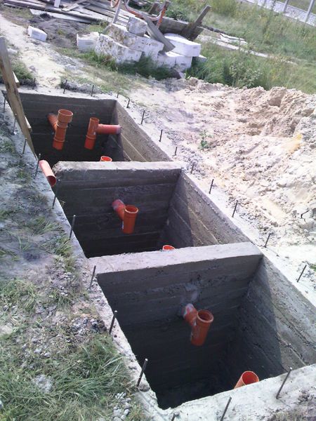
Installation of a monolithic structure
- The edges of the excavated pit are carefully leveled and the formwork for the walls, bottom and partitions is set. In the third section, the bottom is not filled. For formwork, boards or SOB sheets are used, they are knocked down with nails.
- The bottom of the pit is covered with sand and gravel, in the last chamber this layer is the highest.
- To reinforce the septic tank, bars with a diameter of 10 mm will be required. Of these, a metal mesh is knitted for the bottom and walls of the structure.
- A thin layer of mortar is poured to the bottom and a reinforcing mesh is laid, concrete is poured again from above.
Attention. The layer of concrete above the reinforcement must be at least 3 cm. After pouring the bottom of the structure, a two-week break is required before work on the walls.
- The walls are poured in stages, 50 cm of concrete is removed at a time.
- After the walls are made, partitions are made. We must not forget about the holes for the overflow pipes.
- The final stage is the manufacture of a monolithic ceiling. For rigidity of the structure, a metal corner is laid out around the perimeter. Hatches and exits for ventilation are left in the ceiling.
 Three-chamber monolithic septic tank
Settling tank made of concrete rings
A common variant of a three-chamber design is a septic tank of three wells made of concrete rings and connected by overflows. Its device takes less time and effort. The rings are lowered by a crane. The main thing is to perform high-quality waterproofing of joints with cement mortar and complete protection of the structure with coating insulation.
Do-it-yourself autonomous cleaning station
Biological treatment station is the best option for a septic tank for a private house. It combines three wastewater treatment processes: mechanical, anaerobic and aerobic. This allows you to achieve maximum disposal of organic waste and process large volumes of sewage waste in a short time. From the installation of the station on their site, many are stopped by its high cost. But it is not necessary to purchase a technological septic tank, you can make it yourself.
For the device of an effective treatment plant, it is necessary to equip a special chamber - an aerotank and install a compressor. The unit will pump air into the chamber, necessary for the life of aerobic bacteria. The choice of a compressor is an individual matter; two types of devices are used for biological stations: screw and membrane.
The screw unit is equipped with a screw rotary mechanism that allows air to be pumped into the chamber. The device works silently, has high power and a long cycle of work.
The septic tank diaphragm compressor is compact in size and easy to maintain. It forcibly pumps air due to the movement of the membrane. There are models with a hydraulic drive that do not require a connection to the power supply. The unit is economical, does not create noise and vibration during operation. It is this model that is recommended for equipping a septic tank. For proper operation of the compressor, the membrane needs to be replaced twice a year.
Advice. Among the high-quality air injection units are the products of companies: Hailea, AER PUMP, Pondtech, Hiblow.
Compressor installation
The power of the equipment is selected according to the performance of the septic tank. The compressor is placed in a container above the septic tank. Its outlet pipe is connected to an aerator - a perforated plastic pipe sealed at the other end, through which air enters the chamber. The unit is connected to the network.
Advice. Before installation, carefully read the instructions and recommendations of the manufacturer
For the operation of the station, a multi-chamber capacity is required, the best option is 5 sections. It can be a monolithic concrete structure or plastic tanks. The process of wastewater treatment occurs according to the following scheme.


