Automation is increasingly being introduced into daily life modern people. And if earlier automated production could be considered the pinnacle of progress, now even everyday life, an apartment or a private house, can be quite simply radically improved by introducing the concept of “ smart House" After all, today “smart home” systems are designed not only to optimize energy costs, but, first of all, to make a person’s life more comfortable. The capabilities of modern smart home systems will be discussed in our article.
To combine home cinema, lighting control, water supply, video surveillance system, climate control, power supply and access control, gas supply and multiroom into one system - this is the task that the smart home system solves today. Let's go through each of the points sequentially, consider what they can do modern systems automation in relation to our everyday life.
Climate control
The microclimate of public and residential premises greatly affects our performance, and our health in general. Indoor air conditions vary depending on the operating modes of climate control equipment. Heating and ventilation equipment, lighting equipment, and other devices - all of this together has a certain overall effect on the human body, on well-being, on health in the end. And the technology is becoming more and more complex.
Automated systems not only allow us to quickly monitor and manage all this equipment, but ultimately take care of our health. Using sensors, the current state of air in the room is monitored, and control panels adjust the operating modes of air conditioners and supply ventilation, and heating. That is, the climate is adjusted automatically to the person’s requirements, which are specified by preliminary settings.
So climate control allows the following. Air quality control depending on the weather outside and the time of day. Timely ventilation of rooms by controlling heating and opening windows.
Control of heated floor operation. Maintenance optimal temperatures and humidity individually in each room. For example, a food storage room requires its own special climate, which differs from the climate in the living room or kitchen, etc.
Control of temperature, humidity, intensity of fresh air flow, air purification system and ozonation. In each room, the conditions should be different, most suitable for each family member, taking into account the place in the house where this room is located: some to the north, some to the south - and the control in each case will be individual.
Drafts are not allowed in the nursery, the bedroom should be warmer, the floor in the bathroom should be heated on time, and there is no need to keep it warm all the time. That is, the control is optimal so that the energy saving effect also takes place.
The setting varies according to the lifestyle of the family or group. On weekends, the heat supply to work areas is reduced or turned off.
Autonomous heating system country house— on the contrary, it turns on on weekends. The boiler is turned on remotely or switched to economy mode, etc. Everything is rationalized to combine efficiency and comfort of life. This especially applies to water supply, electricity supply and heat supply.
Entertainment
It’s been a long time since you’ve surprised anyone with a home theater. But manage from different places sound and video, as well as stereo systems located throughout the apartment - these functions are implemented using the “smart home” system.
The home theater is connected to an automated system, and the entire complex of multimedia equipment, along with auxiliary devices, is harmoniously integrated into the apartment. There can be several audio and video sources, and they can be multi-channel: Acustic systems, receivers, plasma panels, projectors - everything is controlled directly or remotely from anywhere in the room.

You can watch movies and shows, listen to music in all rooms or just a few, program a scenario and activate it with one button from the touch panel or from the remote control. The script program can be entered into individual conditions: the blinds close, the lights go out or become less intense, the plasma panel turns on, the projector extends, the player starts.
Script programs can be edited, timed for automatic launch, and related settings for watching movies can be set, for example, turning on the air conditioner near the place where the home theater is installed if the weather is hot.
The “multiroom” function is exactly the function that allows you to hear sound or watch video in several independent areas of the apartment. It becomes possible to adjust the volume from any room, each of which has push-button or touch, wall or tabletop control panels, and also has remote controls remote control.
What could be a more expressive sign of the intelligence of a smart home system than smart control lighting? Lighting in a smart home is truly smart and therefore economical. Electricity resources in an apartment, house or office are used as economically as possible, without unnecessary waste.

The advantage of an automated lighting control system is that, based on data from external and external lighting sensors, as well as timers, it allows you to turn on and off the light of the desired brightness and only where it is really necessary. In addition, they open up wide scope for creativity. In addition, the option to simulate the presence of hosts is available.
The modern “smart home” system is a complex of technologies for comfort, safety and efficiency. Stability is ensured by integration in the event of a centralized power supply failure, so that the electronics remain operational at all times.

Batteries and inverters, chargers and liquid fuel generators are installed in the system and integrated in software. In the event of a power outage, the system will automatically switch to a backup source, as a last resort The batteries will continue to power security systems and critical equipment.
Automated security system
The smart home system includes, as part, security and fire alarm and video surveillance, so that both the owners’ stay in the house and their absence would be safe for both the house and the owners themselves. A video intercom and a perimeter security system can be installed here to protect against uninvited guests.
As for security in general, the “smart home” system is capable of providing: protection against short circuits in electrical wiring, protection against water leaks, protection against gas leaks by triggering a smoke sensor and turning on an autonomous fire extinguishing system, autonomous power supply, alarm, automatic call to the rescue service .
Thus, a “smart home” will protect itself and its owners from any dangerous situations, because the system can include: automated gates and doors, automatic security shutters, a video surveillance system, security alarm, presence sensors, smoke sensors, gas leaks, etc.
Controlling access to the premises, video surveillance of adjacent areas, turning on floodlights when penetrating the perimeter are three more pluses in the treasury of advantages. Through the Internet, the owner will be able to remotely receive a picture from any of the cameras of the video surveillance system, this also includes the video baby monitor function.
Video surveillance as such

Intelligent video surveillance is one of the main components modern "smart houses". Video cameras connect to the Internet and allow you to access them from anywhere in the world.
The owner can be abroad, while quickly observing any of the zones, and the video cameras here can be controlled. For example, controllable cameras are usually equipped with gates, courtyards, nearby buildings, and areas near apartment doors. The operation of the video camera can be interfaced with a motion sensor, and signals can be sent to the control center.
The Internet and satellite television networks, as the main sources of information, are conveniently integrated into smart home systems today. While inside the house, the owner can receive information and send it to various rooms, televisions and monitors. This also applies to the transmission of information received from video surveillance systems. Thanks to the multiroom function, all these possibilities open up. Of course, it is possible to set up remote control via the Internet if desired.

Control with mobile phone via direct voice commands and SMS is available today for owners of smart home systems. You can also set up phone call forwarding to your mobile phone if you are away from home, even if you are in another country.
If necessary, you can let guests into the house by simply sending the appropriate command from your mobile phone to your automated system. Similar opportunities can be conveniently implemented via the Internet; all you need to do is find Wi-Fi for your smartphone or laptop.
Andrey Povny
chouck December 4, 2012 at 6:16 pm
From home automation and smart homes in general to a specific example
- DIY or Do It Yourself
The main reason that home automation systems have not yet become so popular is the emphasis on lighting that is usually placed when promoting them. After all, flashing lights (like LEDs on an Arduino) without getting up from the couch is self-indulgence that has no practical significance and pushes people away from serious thoughts about implementing and using home automation systems in their homes and apartments. Nobody needs to blink the light (which is usually what 90% of the functionality is for), but for example, controlling the heating individually in each room is convenient and saves energy = money. Sky-high prices for the components of ready-made home automation systems that are sold at low cost, together with the prices for their integration, only add fuel to the fire. I hasten to assure you that the most expensive component we will have is the 20 dollar Arduino Mega. If we consider the issue as a whole, I see only the following list of tasks that make practical sense to automate centrally:
> climate control temperature (heating/air conditioning) and humidity (humidifier/dehumidifier),
> control of natural light (blinds, shutters, awnings)
> and management of watering of lawns, flower beds and lawns around the house (if there are any and they still need to be watered).
Of the decentralized systems, it is convenient to have a local (without central control, 1-2 sensors that directly control the activation of the backlight) triggered by motion (presence) sensors, low-power LED backlight stairs (sometimes floors) and parts of tables in the kitchen that are shaded from conventional ceiling lighting wall cabinets and shelves. This same illumination, in combination with those listed above, is indispensable at night when you need, without waking up anyone, and especially yourself, to get into the kitchen (and cut something off there and eat without sharing with anyone) or to another establishment without stumbling about thoughtfully scattered children's toys. It also makes sense to turn on the main lighting with motion sensors ONLY in technical rooms: closets, storage rooms, garage, laundry rooms, etc. Motion sensors and centralized systems not practical to use for basic lighting in residential areas. External and decorative holiday lighting at home is most conveniently turned on from cheap ready-made units with lighting sensors and/or timers. Real security systems connected to response services (not just sensors and web cameras scattered around the house) usually does not make sense to mix with smart home systems for many reasons.
So let's start with the most relevant. The ideal object is heating that can be controlled, for example: electric (batteries on wheels in a socket and wall batteries) and centralized or not very heating of a private house. In my example, we will consider working with the Thermo Pump system (Heat Pump in North America) with oil heating via direct connection to the existing Control Unit (thermostat) and additional devices. In the first version of the system, I used X10 protocol devices and sockets. But unfortunately, they performed poorly, due to the slow interface and very loud clicks when switching, which woke up everyone at home. Subsequently, I converted the system to radio sockets, which turned out to be much simpler and quieter than x10. These outlets are available in a huge range of radio frequencies and voltages. All this is applicable to a huge variety of other systems. It all started when my friend and my neighbor unobtrusively dripped on my head about the huge role of the wonderful miracle - Arduino in modern society and that I, as a person who knows how and loves to hold a soldering iron, am simply obliged to become infected with this Arduino mania as soon as possible. I brushed it off in every possible way and said that the area of practical (not robotic toys) application of her home is very doubtful and making sequentially lit LED strips for illuminating the steps of a staircase based on a powerful microcontroller (instead of one shift register and generator) is just a cannon and the rest is self-indulgence . But still, they managed to plant the seed of Arduino in my head and, like all seeds, with the arrival of spring and the approach of summer, a sprout began to break through. I don't like hobby projects for the sake of projects themselves. Some practical side must be present, and especially since resource ($ and time) intensive projects for a family man must also have a high WAF (Wife acceptance factor) or, as my Dad says, it can be easily legalized.
And as always, laziness was the engine of progress. We sat a little after noon on the veranda, the sun was pleasantly hot, and at the same time our little son was sleeping in the bedroom on the top floor, and judging by the Chinese thermometer for 2 dollars (which we still had to get to and look at without waking up our son)  the temperature was over 26. So now we need to go into the living room and turn on the central air conditioning, and then we also need to turn it off so that it doesn’t turn on every time the temperature rises a little. It’s especially unpleasant to do this at night in the summer; when you’re frozen under a light blanket, you have to jump up and, again, without waking up everyone in the household, run into the living room to the remote control and turn off this achievement of the last century. That’s when I realized that it was time to stop such disgrace and call a friend with the words “Where is your vaunted Ardunya, Give her here now, we’ll see what she’s capable of!” I’ll say right away that I didn’t choose it at all and didn’t think that it would turn out to be so useless (for example, in working with strings) and even out of anger and powerlessness to fight it, I almost moved to STM32 in the middle of the project. In the end, he still stayed with her, but first things first.
To make it easier to understand why everything was done this way and how you can spread my experience and achievements on your bread, let’s start with a description of what I have/had at hand:
1) A private house in Canada (I would like to say that it’s mine, but of course it belongs to the bank and no matter how absurd it may sound, it’s not even profitable to have it fully paid at current rates) built in 1959, as they call them here Split Level, those two-story house but half it is shifted vertically relative to the other half by half the floor.
2) Arduino Uno(later, due to the small number of I/O for X10 and radio, Mega was required)
3) expensive and native Ethernet Shield. I was unable to launch something and find an adequate library for the ENC28J60
4) Desire, time and some money.
As is customary here, the bedrooms are on the top floor and for me it turns out to be half a floor above the living room where the ominous control panel for the heating and cooling system is located, screwed to the wall. Here such systems are called HVAC (heating, ventilation, and air conditioning) but in fact it is an ordinary huge (tens of thousands of BTUs or they measure them here in tons of something) split air conditioner with an external heat exchanger and compressor located on the street and inside the heat exchanger is built into a central ventilation system, which with a one and a half kilowatt fan takes air from the floor level of the living room and drives it through two heat exchangers (one to the air conditioner, the other from the fuel oil or gas burner) and drives it through a system of boxes into each room. The convenience and the very name of the heat pump is due to the fact that this device can drive freon in both directions and, accordingly, not only cool but also heat the air in the house. It should be noted that it can heat it more or less efficiently only if it is warm enough outside, more than 0 or -5 (depending on the model and design). If it’s cold, the heat pump won’t work, and that’s exactly what a tank of fuel oil or gas is needed for.
I started my project and ambitions small, so let’s look at how this HVAC is made and how to control it. In fact, it turns out that the devil is not so scary. One of the conveniences is the liquid standardization of everything domestic and not very much in America, this allows you to cross hedgehogs with snakes according to an open, simple (sometimes too) and well-known (usually ancient, common) protocol/standard. In our case, the system itself (burner fan, heat exchangers can be bought from one manufacturer, air conditioner from a second, a humidifier from a third, and the Control Unit for all this from a fourth. Honestly, I don’t know if they are also called/controlled similar devices in Europe, but I think that everything is either copied or very similar. As far as I understand, such systems already exist in Russia and they are transported anywhere/cheaper, so you have a high chance of encountering just such a system. Let's look at a typical system wiring diagram before we start cutting into the system. 
As we see, almost everything is clear at first glance. The only thing that needs to be clarified is that the control unit is powered and the heat pump itself is controlled by 24 volts. which are supplied from the input transformer R and C. Line C is common and is always connected. Accordingly, when R (short circuit) is applied to Y, O, W or G, the corresponding one is turned on. block. We will build on this. So if they include it, then why are we worse? Let's make it ours new system will complement the existing one. Those controls can be carried out from the old remote control and controller as before, but only when necessary, Arduino can disconnect the old system from control and take the grooves into its own hands and then give them back. We install the relays. 
Moreover, we place them so that without power and generally disconnected, they retain the same design. R-0 disables the standard control module and transfers control to our Arduino. R-1-4 supplies the required voltage to the corresponding line. This control voltage R is supplied to each relay green wire. Of course, it’s good to control, but the system is serious and if we accidentally or not turn on something wrong or in the wrong combination. For example, the heat exchanger will heat up and the fan will not circulate air and remove heat from it; it can overheat and lead to a fire, but we don’t need this at all. To avoid such situations, let's make triple protection. And so the first bastion will be voltage sensors on each line S1-4 (there should be 4 of them). 
They consist of a diode, two resistors (divider) and a small electrolyte. This could be a hinged assembly like in the photo. As a result, we can use Arduino to know whether there is actually voltage on each of the control lines or not. Accordingly, if the current state of the control lines (Y, O, W, G) does not correspond to what it should be, we display an error code and turn off the system. The next bastion is our additional temperature sensor in the heat exchanger chamber (plenum sensor). If it is too hot or cold there (close to 0C), then we again display the code and turn off the system. Obviously, it is impossible to power the relay directly from the Arduino outputs, so you must either pile a transistor on each relay or buy a ready-made module with several relays and transistors on one board. I buy 99% of my components on eBay. For example, eBay is full of these 8 channel modules (8 Channel Electronic Relay Module) for about $9. or you can buy 4+2 (since in fact we only need 5 and one spare) 
I used Chinese digital DHT22 as temperature and humidity sensors  which have proven themselves well. They only need three wires +5, GNd and Data. The wires can be long enough without loss of accuracy and signal. One sensor is thrown outside into the shade and under a canopy from direct moisture. One sensor in the house.
  In a house already built many years ago, usually the most a big problem This is to run new wires, so I tried to use the current wiring as much as possible. There are several libraries for DHT22. I had problems with all of them except this one. I placed the internal DHT22 next to the wall control panel. If your house, like mine, once had an HVAC control system, then you should have a 6-wire cable running from the control unit to the place where the remote control with the indicator and buttons hangs. Modern remote controls (like mine) require only 2 wires. Thus, we have 4 already laid wires at our disposal. In them we run +5V, GND, Data for the internal DHT22 and to the last Serial(UART) Tx from Arduino to display information on the display.
As a display, I used a small (2.5 cm) OLED screen with a serial interface.  YES, it is a little expensive, but there are several unique differences from similar ones available: The presence of a Serial (UART) interface, which allows you to use only one wire to connect it, the presence of five digital pins on the screen controller (where we will connect an RGB LED to additionally display the system status) and finally, compactness combined with contrast and excellent readability both in bright light and at night, and it does not illuminate the entire corridor at night like any LCD with the backlight constantly on.
Next, the problem arose of how to place temperature sensors in each room, without additional wires, power and radio modules. As a sensor, I chose a digital DS18B20, (having good accuracy +- 0.5C) which requires only two wires (ground and signal). You can hang many of them in parallel on these 2 wires (each has its own unique MAC address). But even stretching two wires in all rooms is hellish work. Then it dawned on me. After all, a telephone cable is laid in all rooms and it is 4-core and in the best case, 2 wires are used for the telephone (usually red and green) and the rest (yellow and black) go through all the places I need and remain free. Thus, without cutting the wires, but only exposing the necessary two, I soldered DS18B20 to them in each room.  The total length of the wires turned out to be quite large, and if the signal wire was supported (at +5V) with the recommended 4.7 kOhm, then in my case the sensors were practically unreadable and I reduced the supporting resistance by half to 2.3 kOhm and everything worked fine.
Then I got confused with the pressure sensor and settled on the expensive BMP085  but it has an I2C interface, which again saves legs and the number of wires. Since it can still read the temperature, I placed it in the basement, where it was closest and easiest to pull new wires (as many as 4). I tried to use standard telephone cables and connectors (RJ11) as much as possible so that the design was disassembled and repairable - suitable for replacement.
  When connecting this barometer to the same I2C bus as the RTC (non-volatile clock module), some not very clear problems arose. They interfered with each other and until I set a short delay before reading the barometer, everything worked unstable. Since short temporary power outages are not that uncommon, and the RTC module
  It costs a penny, I added it for non-volatile time. mainly needed when using x10. Using it, I wanted to automatically synchronize it with NTP via the Internet (since we already have it), but somehow I couldn’t cross the webduino server and NTP. As a result, the NTP time (Unix epoch) is sent to the Arduino (and updated by the RTC) every time any settings or modes are changed in the web interface. Which has its drawbacks since it is taken by JavaScript from the time on the current computer or mobile device and is not always accurate and in the correct time zone.
I send commands to my Arduino radio sockets on the air using a penny ($2) transmitter  module. There are a dime a dozen of them on eBay (search for “RF transmitter 315 Mhz..”) and in any store. The only thing you need to do is choose the right radio frequency that matches your outlets. Unfortunately, my sockets were not supported correctly by the standard RCswitch library. in the library description there is a list of supported chips, but don’t be upset if yours is not on the list, it worked for me after analyzing the ether manually and without the library. Much has been written about similar sockets and working with the library. In particular here: http://habrahabr.ru/post/213425 http://habrahabr.ru/post/212215 I used 110V sockets
  . Despite the fact that radio control requires a non-standard solution, it is the simplest and most cost-effective solution to the problem at hand. Namely, turn on and off electric batteries or any other device (not necessarily resistive) by time or manually and sometimes turn on and off the outside lights. Insteon, Zwave and others have many sometimes unnecessary additional functions but they are an order of magnitude more expensive and have problems with the openness of the interface so that Arduino can send simple commands to devices. The only problem with the x10, Insteon and other outlets is that they click very loudly when switching. This is especially annoying on a quiet night. One more nuance: x10 was sharpened and popular in North America and accordingly under 110 Volts. Here everyone chooses for themselves. Or pay a lot for:
Z-Wave - there are no ready-made sockets, there are strangely shaped relay modules that also click but are quieter and they have to be hidden somewhere, somehow in the walls, then walled up, it is not clear how to service them - change/repair them. But USB modules appeared for sending commands. But for this you still need a microcomputer (maybe a router will do) with the correct OS drivers, etc.;
Insteon - there are sockets, but they also click disgustingly like x10 and, as far as I understand, there is no open module for sending commands and the system is again designed for 110V;
It's up to you to bother with integration and sending commands to this network or to pay 5-10 times less for each radio device and, if necessary, tweak the code for it. Like any other thing, everything for 110V costs less. Of course, there are also extreme ways, such as the idea described by several authors here, the idea of entangling the entire apartment (house) with a pair (and in fact a bundle) of hammer wires and manually assembling each control and controlled device from scratch using the 1-Wire protocol. Some have gone even further and are developing their own protocols...
Also, as a kiter, I screwed on an anemometer (wind speed sensor). To measure it, I used a cup sensor I had on hand with a reed switch closing 1 kOhm between two contacts when the cups rotated.  The program uses an interrupt and measures the number of times +5V is applied (transition from 0 to 1) to the digital input (connected to 5 kOhms at the same +5V). This value is multiplied by a coefficient suitable for your sensor and the wind speed in knots is obtained from the number of short circuits in one second. Also, for each hour the maximum and minimum speed values (gusts) are measured and the maximum per hour is displayed. The web displays the current and maximum. Each sensor must be calibrated individually and the correct coefficient must be selected. To control the garage door, I used a spare radio remote control from it and, using an additional relay (sixth), emulated pressing a button on the remote control (by opening the remote control and soldering the buttons into the contacts).
The communication protocol of a standard thermopump control unit with its remote control (usually 2 wires) is usually closed and our arduino cannot know what mode and settings are set in the standard control unit, but with the help of our sensors we can know what mode the HVAC is in now, and although they also have there is a temperature sensor in the heat exchanger additional protection using Arduino won't hurt. I am often asked: Isn’t it scary for me to trust Arduino to control such a responsible system in my home? My code is open and transparent. I understand what is happening and can always catch and correct inaccuracies (if any remain after six months of using the system). And most importantly, I can add any functions that I need. In the same box there is most likely a less powerful controller and of course there is nothing that can be changed or added. Without an Arduino, adding again limited functions such as access from the Internet to a standard control unit costs a new box of hundreds of dollars. It all started Not because I wanted to save money and I needed functions that were convenient for me and that I couldn’t buy from equipment manufacturers at any price. But of course, if you take into account the cost of the man-hours spent by me, and even by you if you simply decide to do something similar based on my and other developments, for this project it is of course cheaper to buy a ready-made one but say goodbye to flexibility and the necessary functions. It’s like installing FreeBSD and painstakingly digging through the flea market of knowledge on the Internet for a long time and for every reason and manually from the command line tweaking it for yourself in comparison with Mac OS, a beautiful ready-made but limited one based on the same BSD. The main one is turning on heating/cooling to the desired temperature not forever or according to a schedule, but only for an hour or 2-4. It sounds simple and convenient, but it is not present in standard control units.
If you want to control only a thermal pump without RF, RTC, barometer and other troubles, the Uno has enough memory and legs (I did just that in the first phase of my project). The full version cannot do without Mega. Let's take a look at the resulting functionality and interface. 
The interface itself is made within just one html page using Ajax technology for exchanging data with the Arduino web server (webduino) and is based on the JQuery Mobile libraries. Therefore, to work, you need several image files and the libraries themselves, which can be replaced with links.
In the upper left corner, we see the moon, this means that according to the day and night settings (in the first line of the blue block) it is now night mode. If it's daytime there will be sun there. Next we see our house. In the house there are a lot of temperatures in each room and in the center the temperature in tenths is the temperature in the living room on the main level. In green at the bottom of the house we see the relative humidity inside the house. To the right of it is a snowflake, this is an indicator that the air conditioner is now working. At this point, the remaining operating modes (heating with a thermopump or AUX or x10) are displayed with different icons. If the icon is muted (translucent), it means the system is in this mode but not active. Those. for example, in air conditioning mode up to a temperature of 21 degrees, but since it is now 20 degrees the air conditioner is not active. If two modes are operating simultaneously, for example heating x10 and heating with a thermopump, then two icons will flash sequentially. To the left and right of the house we see rays, when pressed they become bright and when pressed again they dim again. This is the inclusion of external lighting near the house. I have outside lights in the backyard and front of the house. Control is transmitted via x10 and the numbers of the corresponding devices are written in html (JS) code, Arduina only sends commands to the device numbers transmitted to it from HTML. To the right of the house we see an automatic garage door. which opens and closes when you press it. Above to the right of the house we see the current (averaged over 1-2 minutes) or maximum per hour wind speed in knots. The wind speed value is highlighted in different colors from blue to red depending on the speed and in accordance with the internationally accepted colors of the Beaufort scale. On the top right we see the temperature outside and below the current atmospheric pressure. The pink background for the pressure value is a graph of its relative change over the last 24 hours (x-time, y-relative pressure value). Under pressure green relative humidity on the street.
Now consider a group of white selectors and the SET button. Use the left selector to select the desired temperature/mode. Right for how long to enable this mode. If the mode is active, the labels will change slightly, as in this example 
If the heating mode is active, then the button will additionally be tinted red and if cooling mode is blue. To turn it off, you need to leave the temperature and the selected mode on the left and the remaining minutes on the right, and then the SET button will change to OFF and pressing it will turn off the mode. Cooling or heating mode is selected automatically depending on the outside temperature. If the street temperature is less than the value of the heat_temp constant described in the html(JS) file, then only heating will be offered, otherwise only cooling.
Now let's look at the blue x10 block. Clicking on the first line opens general settings: ON - All sockets are always on (for example in summer), OFF all sockets are always turned off (for example if you are on vacation), Split - come into force individual settings groups and rooms. Next, you can choose from what hour the day begins and from what time the night begins.  To save the settings, do not forget to click the Apply button below. further, each line reflects a group of rooms which can consist of one or more rooms. I made a grouping by floors in my house. Some floors have only one room and some have more. For each group we can set the ON mode - all sockets in this group are always on, OFF all sockets in this group are always off (for example, you need to turn on the vacuum cleaner and if the battery is running at the same time, it will blow the fuse), Split (available only for groups with more than one room) - individual settings of rooms within the group come into effect, Day - maintain the specified temperature only during the day (always off at night), Day&Night - maintain the specified temperature for the day and a different temperature at night. All of the above are available for each room with the exception of Split. For the changes to take effect, do not forget to click Apply below.
The very last line is to set the Override mode. This mode was made to force the sockets in the selected room or lamp to turn on for a while. For example, you need to heat up the room as much as possible for a certain period in order for the child to have a massage there and after an hour continue to maintain the usual temperature in it. Or turn on the light outside for half an hour. On the left you select the room on the right for how long to turn on the mode and press the Override button. If you need to turn off the mode ahead of schedule, select OFF on the right and click Override. All information is updated every upd_interval (constant from the html file) seconds. Default = 60 seconds. When the information is updated, the entire top part of the page with the house blinks.
I would also like to talk about the concept of combining sockets (pool). Let's say you have one a large room One battery alone is not able to heat it at -5, or it will take a very long time to heat up. You can install a second RF socket with the same code/address and plug a second battery into it and they will both always turn on. Which, at a relatively warm temperature, will lead to frequent clicking and turning on and off of these two or more batteries. There is another option: you combine these batteries into a pool in the Arduino code x10pools=(0,0,0,0,0,12,0,0,13,0,0,0,0,0,0,0,0) . Zero means that there is no pool for a given socket address; the number means the address of a child socket of the pool. The child is turned on if it is colder outside than poolt (constant from the html file) or the gap between the desired temperature in the room and the current one is greater than delta_temp * poolf (constants from the html file). I would like to say more about delta_temp (constant from the html file) this is Temperature Delta. It is needed so that the modes do not often turn on or off, since the sensor readings may jump a little +-. The heating turns on if the current temperature is less than (desired - delta_temp) and turns off if it is more than (desired + delta_temp). The default is 0.5 Deg C.
Now let's look at the issue of security. Of course, you can’t leave control of your home accessible to everyone. Since our system consists of a client (JS Ajax html page) and a server (Arduino), you can organize different levels of security. For example, you can put an HTML page on your computer, phone, tablet, etc. (without exposing it to public hosting) and then only you (from devices that have this file) will be able to open this control panel for your home systems. The Arduino web server is based on the internal IP and therefore if you do not forward it on the router to the outside world, then the Arduino itself can only be reached from your internal network. Access to the HTML page itself can be password protected on the Web server where you want to post it. It is also fashionable to raise the HTTPS server in relation to it. The simplest and, in my opinion, quite reliable is public hosting of the page, but the page itself does not connect anywhere when launched unless the Arduino server address is passed to it as a parameter (pre-configured Dinamic DNS and Port Foewarding). It looks like this: in the browser, enter the following link: http://myhosting.com/index.html?http://myhome.slyip.net:8081/hvac. If an attacker accidentally stumbles upon your client page, he will not be able to do anything with it without knowing the address of the Arduino server. This is the simplest and most convenient compromise option that I currently use. Yes, I also don’t like this whole design with a poor (slow, not supporting HTTPS, etc.) Arduino Web Shield server, in addition to which I also have to host the client page with the icon somewhere separately. And as soon as I receive the famous TP-LINK TL-WR703N from China  a router that in the blink of an eye turns into a wifi bridged web server with a Serial (UART) interface to Arduine, I will immediately screw it to the Arduine (or it to it) and throw out this shield and disconnect the wire. Thus, it will turn out even more than what I wanted so unsuccessfully to achieve from the STM32 controller, namely, that everything would be in one device (not a separate client page and a separate executive server) and a normal web server on which a decent degree of convenience, speed and security can be implemented.


B for last
Good day! Today's article will focus on home automation.
Thanks to the introduction of automation, we can control various devices and devices from a mobile phone or other device anywhere in the world. The heart of such a system is the controller. This could be Arduino, Raspberry pi, BeagleBone Black, Spark Core, DigiSpark or ExtraCore.
For manual control Such a system can use infrared remote control technology. With its help, you can control any device (AC/DC) using a simple TV remote control.
Step 1: Required Parts
- Arduino Nano;

- 5V relay;

- LEDs;

- Transistor BC548;

- Plug/socket;
- 5V power supply;
- Frame;
- Screw terminal blocks;
- Panel;

- IR radio receiver;

- Foil PCB;

- DipTrace - automated end-to-end design system electrical diagrams and printed circuit board layouts.
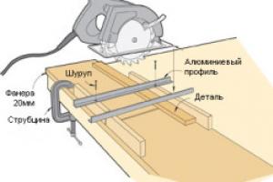
Step 2: We make the board using the LUT method


We distribute the fee. We print the diagram on photo paper using a laser printer. We clean the surface of the workpiece (foiled textolite) from grease and dust. We transfer the circuit from photo paper to the board, and then etch it with ferric chloride. After this, we drill holes with a mini-drill (the diameter of the holes should correspond to the terminals of the radio components). The manufacturing process is described in more detail in the article.


Step 3: Attach the Components

The first thing you should start with is to familiarize yourself with the pinout of the transistor pinouts, connections to relays, LED pinouts, power supply and IR radio receiver, etc. Next, we will arrange all the parts and very carefully solder them onto the board.
On printed circuit board the line to which the emitter of the transistor is connected is always connected to ground.

The Arduino nano outputs 5V, so the positive pin of the LED is connected to the Arduino pin.
The negative terminal of the LED is connected to the base of the transistor (the LED is used as an on/off status indicator).

Pins 7,8,9 are used to supply on/off output signals to the switches.
Pin 11 is used to receive a signal from the IR receiver.

Lastly, connect the 5V power supply.

Step 4: Read the control values

Download the library for IR and install it in the Arduino IDE. Open the Arduino IDE and click on File—Example—IRremote—IRrecvDemo.

The main reason that home automation systems have not yet become so popular is the emphasis on lighting that is usually placed when promoting them. After all, flashing lights (like LEDs on an Arduino) without getting up from the couch is self-indulgence that has no practical significance and pushes people away from serious thoughts about implementing and using home automation systems in their homes and apartments. Nobody needs to blink the light (which is usually what 90% of the functionality is for), but for example, controlling the heating individually in each room is convenient and saves energy = money. Sky-high prices for the components of ready-made home automation systems that are sold at low cost, together with the prices for their integration, only add fuel to the fire. I hasten to assure you that the most expensive component we will have is the 20 dollar Arduino Mega. If we consider the issue as a whole, I see only the following list of tasks that make practical sense to automate centrally:
> climate control temperature (heating/air conditioning) and humidity (humidifier/dehumidifier),
> control of natural light (blinds, shutters, awnings)
> and management of watering of lawns, flower beds and lawns around the house (if there are any and they still need to be watered).
Of the decentralized systems, it is convenient to have local (without central control, 1-2 sensors that directly control the switching on of the backlight) low-power LED lighting of stairs (sometimes floors) and parts of tables in the kitchen that are shaded from conventional ceiling lighting by wall cabinets and shelves, triggered by motion (presence) sensors. This same illumination, in combination with those listed above, is indispensable at night when you need, without waking up anyone, and especially yourself, to get into the kitchen (and cut something off there and eat without sharing with anyone) or to another establishment without stumbling about thoughtfully scattered children's toys. It also makes sense to turn on the main lighting with motion sensors ONLY in technical rooms: closets, storage rooms, garage, laundry rooms, etc. Motion sensors and centralized systems are not practical to use for basic lighting in residential areas. External and decorative holiday lighting at home is most conveniently turned on from cheap ready-made units with lighting sensors and/or timers. Real security systems connected to response services (not just sensors and web cameras scattered around the house) usually do not make sense to mix with smart home systems for many reasons.
So let's start with the most relevant. The ideal object is heating that can be controlled, for example: electric (batteries on wheels in a socket and wall batteries) and centralized or not very heating of a private house. In my example, we will consider working with the Thermo Pump system (Heat Pump in North America) with oil heating via direct connection to the existing Control Unit (thermostat) and additional devices. In the first version of the system, I used X10 protocol devices and sockets. But unfortunately, they performed poorly, due to the slow interface and very loud clicks when switching, which woke up everyone at home. Subsequently, I converted the system to radio sockets, which turned out to be much simpler and quieter than x10. These outlets are available in a huge range of radio frequencies and voltages. All this is applicable to a huge variety of other systems. It all started with the fact that my friend and his neighbor unobtrusively dripped on my head about the huge role of the wonderful miracle - Arduino in modern society and that I, as a person who knows how and loves to hold a soldering iron, am simply obliged to become infected with this Arduino mania as soon as possible. I brushed it off in every possible way and said that the area of practical (not robotic toys) application of her home is very doubtful and making sequentially lit LED strips for illuminating the steps of a staircase based on a powerful microcontroller (instead of one shift register and generator) is just a cannon and the rest is self-indulgence . But still, they managed to plant the seed of Arduino in my head and, like all seeds, with the arrival of spring and the approach of summer, a sprout began to break through. I don't like hobby projects for the sake of projects themselves. Some practical side must be present, and especially since resource ($ and time) intensive projects for a family man must also have a high WAF (Wife acceptance factor) or, as my Dad says, it can be easily legalized.
And as always, laziness was the engine of progress. We sat a little after noon on the veranda, the sun was pleasantly hot, and at the same time our little son was sleeping in the bedroom on the top floor, and judging by the Chinese thermometer for 2 dollars (which we still had to get to and look at without waking up our son) the temperature was over 26. So now we need to go into the living room and turn on the central air conditioning, and then we also need to turn it off so that it doesn’t turn on every time the temperature rises a little. It’s especially unpleasant to do this at night in the summer; when you’re frozen under a light blanket, you have to jump up and, again, without waking up everyone in the household, run into the living room to the remote control and turn off this achievement of the last century. That’s when I realized that it was time to stop such disgrace and call a friend with the words “Where is your vaunted Ardunya, Give her here now, we’ll see what she’s capable of!” I’ll say right away that I didn’t choose it at all and didn’t think that it would turn out to be so useless (for example, in working with strings) and even out of anger and powerlessness to fight it, I almost moved to STM32 in the middle of the project. In the end, he still stayed with her, but first things first.
To make it easier to understand why everything was done this way and how you can spread my experience and achievements on your bread, let’s start with a description of what I have/had at hand:
1) A private house in Canada (I would like to say that it is mine, but of course it belongs to the bank and no matter how absurd it may sound, having it fully paid off at current rates is not even profitable) built in 1959, as they call them here, Split Level those house It's two stories high, but half of it is shifted vertically relative to the other half by half a floor.
2) Arduino Uno (later, due to the small number of I/O for X10 and radio, Mega was required)
3) expensive and native Ethernet Shield. I was unable to launch something and find an adequate library for the ENC28J60
4) Desire, time and some money.
As is customary here, the bedrooms are on the top floor and for me it turns out to be half a floor above the living room where the ominous control panel for the heating and cooling system is located, screwed to the wall. Here such systems are called HVAC (heating, ventilation, and air conditioning) but in fact it is an ordinary huge (tens of thousands of BTUs or they measure them here in tons of something) split air conditioner with an external heat exchanger and compressor located on the street and inside the heat exchanger is built into a central ventilation system, which with a one and a half kilowatt fan takes air from the living room floor level, drives it through two heat exchangers (one to the air conditioner and the other from an oil or gas burner) and drives it through a system of ducts to each room. The convenience and the very name of the heat pump is due to the fact that this device can drive freon in both directions and, accordingly, not only cool but also heat the air in the house. It should be noted that it can heat it more or less efficiently only if it is warm enough outside, more than 0 or -5 (depending on the model and design). If it’s cold, the heat pump won’t work, and that’s exactly what a tank of fuel oil or gas is needed for.
I started my project and ambitions small, so let’s look at how this HVAC is made and how to control it. In fact, it turns out that the devil is not so scary. One of the conveniences is the liquid standardization of everything domestic and not very much in America, this allows you to cross hedgehogs with snakes according to an open, simple (sometimes too) and well-known (usually ancient, common) protocol/standard. In our case, the system itself (burner fan, heat exchangers can be bought from one manufacturer, air conditioner from a second, a humidifier from a third, and the Control Unit for all this from a fourth. To be honest, I don’t know if similar devices are also called/managed in Europe, but I think that everything is either licked or very similar .As far as I understand, such systems already exist in Russia and they are transported from anywhere/cheaper, so you have a high chance of encountering just such a system.Let's look at the diagram of a typical system connection before we start cutting into the system.
As we see, almost everything is clear at first glance. The only thing that needs to be clarified is that the control unit is powered and the heat pump itself is controlled by 24 volts. which are supplied from the input transformer R and C. Line C is common and is always connected. Accordingly, when R (short circuit) is applied to Y, O, W or G, the corresponding one is turned on. block. We will build on this. So if they include it, then why are we worse? Let's make sure that our new system complements the existing one. Those controls can be carried out from the old remote control and controller as before, but only when necessary, Arduino can disconnect the old system from control and take the grooves into its own hands and then give them back. We install the relays.
Moreover, we place them so that without power and generally disconnected, they retain the same design. R-0 disables the standard control module and transfers control to our Arduino. R-1-4 supplies the required voltage to the corresponding line. This control voltage R is supplied to each relay via the green wire. Of course, it’s good to control, but the system is serious and if we accidentally or not turn on something wrong or in the wrong combination. For example, the heat exchanger will heat up and the fan will not circulate air and remove heat from it; it can overheat and lead to a fire, but we don’t need this at all. To avoid such situations, let's make triple protection. And so the first bastion will be voltage sensors on each line S1-4 (there should be 4 of them).
They consist of a diode, two resistors (divider) and a small electrolyte. This could be a hinged assembly like in the photo. As a result, we can use Arduino to know whether there is actually voltage on each of the control lines or not. Accordingly, if the current state of the control lines (Y, O, W, G) does not correspond to what it should be, we display an error code and turn off the system. The next bastion is our additional temperature sensor in the heat exchanger chamber (plenum sensor). If it is too hot or cold there (close to 0C), then we again display the code and turn off the system. Obviously, it is impossible to power the relay directly from the Arduino outputs, so you must either pile a transistor on each relay or buy a ready-made module with several relays and transistors on one board. I buy 99% of my components on eBay. For example, eBay is full of these 8 channel modules (8 Channel Electronic Relay Module) for about $9. or you can buy 4+2 (since in fact we only need 5 and one spare)
I used Chinese digital DHT22 as temperature and humidity sensors which have proven themselves well. They only need three wires +5, GNd and Data. The wires can be long enough without loss of accuracy and signal. One sensor is thrown outside into the shade and under a canopy from direct moisture. One sensor in the house. In a house that's been built many years ago, the biggest challenge is usually running new wires, so I tried to make the most of the current wiring. There are several libraries for DHT22. I had problems with all of them except this one. I placed the internal DHT22 next to the wall control panel. If your house, like mine, once had an HVAC control system, then you should have a 6-wire cable running from the control unit to the place where the remote control with the indicator and buttons hangs. Modern remote controls (like mine) require only 2 wires. Thus, we have 4 already laid wires at our disposal. In them we run +5V, GND, Data for the internal DHT22 and to the last Serial(UART) Tx from Arduino to display information on the display.
As a display, I used a small (2.5 cm) OLED screen with a serial interface. YES, it is a little expensive, but there are several unique differences from similar ones available: The presence of a Serial (UART) interface, which allows you to use only one wire to connect it, the presence of five digital pins on the screen controller (where we will connect an RGB LED to additionally display the system status) and finally, compactness combined with contrast and excellent readability both in bright light and at night, and it does not illuminate the entire corridor at night like any LCD with the backlight constantly on.
Next, the problem arose of how to place temperature sensors in each room, without additional wires, power and radio modules. As a sensor, I chose a digital DS18B20, (having good accuracy +- 0.5C) which requires only two wires (ground and signal). You can hang many of them in parallel on these 2 wires (each has its own unique MAC address). But even stretching two wires in all rooms is hellish work. Then it dawned on me. After all, a telephone cable is laid in all rooms and it is 4-core and in the best case, 2 wires are used for the telephone (usually red and green) and the rest (yellow and black) go through all the places I need and remain free. Thus, without cutting the wires, but only exposing the necessary two, I soldered DS18B20 to them in each room. The total length of the wires turned out to be quite large, and if the signal wire was supported (at +5V) with the recommended 4.7 kOhm, then in my case the sensors were practically unreadable and I reduced the supporting resistance by half to 2.3 kOhm and everything worked fine.
Then I got confused with the pressure sensor and settled on the expensive BMP085 but it has an I2C interface, which again saves legs and the number of wires. Since it can still read the temperature, I placed it in the basement, where it was closest and easiest to pull new wires (as many as 4). I tried to use standard telephone cables and connectors (RJ11) as much as possible so that the design was disassembled and repairable - suitable for replacement. When connecting this barometer to the same I2C bus as the RTC (non-volatile clock module), some not very clear problems arose. They interfered with each other and until I set a short delay before reading the barometer, everything worked unstable. Since short temporary power outages are not that uncommon, and the RTC module It costs a penny, I added it for non-volatile time. mainly needed when using x10. Using it, I wanted to automatically synchronize it with NTP via the Internet (since we already have it), but somehow I couldn’t cross the webduino server and NTP. As a result, the NTP time (Unix epoch) is sent to the Arduino (and updated by the RTC) every time any settings or modes are changed in the web interface. Which has its drawbacks since it is taken by JavaScript from the time on the current computer or mobile device and is not always accurate and in the correct time zone.
I send commands to my Arduino radio sockets on the air using a penny ($2) transmitter module. There are a dime a dozen of them on eBay (search for “RF transmitter 315 Mhz..”) and in any store. The only thing you need to do is choose the right radio frequency that matches your outlets. Unfortunately, my sockets were not supported correctly by the standard RCswitch library. in the library description there is a list of supported chips, but don’t be upset if yours is not on the list, it worked for me after analyzing the ether manually and without the library. Much has been written about similar sockets and working with the library. In particular here: http://habrahabr.ru/post/213425 http://habrahabr.ru/post/212215 I used 110V sockets . Despite the fact that radio control requires a non-standard solution, it is the simplest and most cost-effective solution to the problem at hand. Namely, turn on and off electric batteries or any other device (not necessarily resistive) by time or manually and sometimes turn on and off the outside lights. Insteon, Zwave and others have many sometimes unnecessary additional functions, but they are an order of magnitude more expensive and have problems with the openness of the interface so that Arduino can send simple commands to devices. The only problem with the x10, Insteon and other outlets is that they click very loudly when switching. This is especially annoying on a quiet night. One more nuance: x10 was sharpened and popular in North America and, accordingly, under 110 Volts. Here everyone chooses for themselves. Or pay a lot for:
Z-Wave - there are no ready-made sockets, there are strangely shaped relay modules that also click but are quieter and they have to be hidden somewhere, somehow in the walls, then walled up, it is not clear how to service them - change/repair them. But USB modules appeared for sending commands. But for this you still need a microcomputer (maybe a router will do) with the correct OS drivers, etc.;
Insteon - there are sockets, but they also click disgustingly like x10 and, as far as I understand, there is no open module for sending commands and the system is again designed for 110V;
It's up to you to bother with integration and sending commands to this network or to pay 5-10 times less for each radio device and, if necessary, tweak the code for it. Like any other thing, everything for 110V costs less. Of course, there are also extreme ways, such as the idea described by several authors here, the idea of entangling the entire apartment (house) with a pair (and in fact a bundle) of hammer wires and manually assembling each control and controlled device from scratch using the 1-Wire protocol. Some have gone even further and are developing their own protocols...
Also, as a kiter, I screwed on an anemometer (wind speed sensor). To measure it, I used a cup sensor I had on hand with a reed switch closing 1 kOhm between two contacts when the cups rotated. The program uses an interrupt and measures the number of times +5V is applied (transition from 0 to 1) to the digital input (connected to 5 kOhms at the same +5V). This value is multiplied by a coefficient suitable for your sensor and the wind speed in knots is obtained from the number of short circuits in one second. Also, for each hour the maximum and minimum speed values (gusts) are measured and the maximum per hour is displayed. The web displays the current and maximum. Each sensor must be calibrated individually and the correct coefficient must be selected. To control the garage door, I used a spare radio remote control from it and, using an additional relay (sixth), emulated pressing a button on the remote control (by opening the remote control and soldering the buttons into the contacts).
The communication protocol of a standard thermopump control unit with its remote control (usually 2 wires) is usually closed and our arduino cannot know what mode and settings are set in the standard control unit, but with the help of our sensors we can know what mode the HVAC is in now, and although they also have There is a temperature sensor in the heat exchanger; additional protection using Arduino will not hurt. I am often asked: Isn’t it scary for me to trust Arduino to control such a responsible system in my home? My code is open and transparent. I understand what is happening and can always catch and correct inaccuracies (if any remain after six months of using the system). And most importantly, I can add any functions that I need. In the same box there is most likely a less powerful controller and of course there is nothing that can be changed or added. Without an Arduino, adding again limited functions such as access from the Internet to a standard control unit costs a new box of hundreds of dollars. It all started Not because I wanted to save money and I needed functions that were convenient for me and that I couldn’t buy from equipment manufacturers at any price. But of course, if you take into account the cost of the man-hours spent by me, and even by you if you simply decide to do something similar based on my and other developments, for this project it is of course cheaper to buy a ready-made one but say goodbye to flexibility and the necessary functions. It’s like installing FreeBSD and painstakingly digging through the flea market of knowledge on the Internet for a long time and for every reason and manually from the command line tweaking it for yourself in comparison with Mac OS, a beautiful ready-made but limited one based on the same BSD. The main one is turning on heating/cooling to the desired temperature not forever or according to a schedule, but only for an hour or 2-4. It sounds simple and convenient, but it is not present in standard control units.
If you want to control only a thermal pump without RF, RTC, barometer and other troubles, the Uno has enough memory and legs (I did just that in the first phase of my project). The full version cannot do without Mega. Let's take a look at the resulting functionality and interface.
The interface itself is made within just one html page using Ajax technology for exchanging data with the Arduino web server (webduino) and is based on the JQuery Mobile libraries. Therefore, to work, you need several image files and the libraries themselves, which can be replaced with links.
In the upper left corner, we see the moon, this means that according to the day and night settings (in the first line of the blue block) it is now night mode. If it's daytime there will be sun there. Next we see our house. In the house there are a lot of temperatures in each room and in the center the temperature in tenths is the temperature in the living room on the main level. In green at the bottom of the house we see the relative humidity inside the house. To the right of it is a snowflake, this is an indicator that the air conditioner is now working. At this point, the remaining operating modes (heating with a thermopump or AUX or x10) are displayed with different icons. If the icon is muted (translucent), it means the system is in this mode but not active. Those. for example, in air conditioning mode up to a temperature of 21 degrees, but since it is now 20 degrees the air conditioner is not active. If two modes are operating simultaneously, for example heating x10 and heating with a thermopump, then two icons will flash sequentially. To the left and right of the house we see rays, when pressed they become bright and when pressed again they dim again. This is the inclusion of external lighting near the house. I have outside lights in the backyard and front of the house. Control is transmitted via x10 and the numbers of the corresponding devices are written in html (JS) code, Arduina only sends commands to the device numbers transmitted to it from HTML. To the right of the house we see an automatic garage door. which opens and closes when you press it. Above to the right of the house we see the current (averaged over 1-2 minutes) or maximum per hour wind speed in knots. The wind speed value is highlighted in different colors from blue to red depending on the speed and in accordance with the internationally accepted colors of the Beaufort scale. On the top right we see the temperature outside and below the current atmospheric pressure. The pink background for the pressure value is a graph of its relative change over the last 24 hours (x-time, y-relative pressure value). Under pressure green relative humidity outside.
Now consider a group of white selectors and the SET button. Use the left selector to select the desired temperature/mode. Right for how long to enable this mode. If the mode is active, the labels will change slightly, as in this example
If the heating mode is active, then the button will additionally be tinted red and if cooling mode is blue. To turn it off, you need to leave the temperature and the selected mode on the left and the remaining minutes on the right, and then the SET button will change to OFF and pressing it will turn off the mode. Cooling or heating mode is selected automatically depending on the outside temperature. If the street temperature is less than the value of the heat_temp constant described in the html(JS) file, then only heating will be offered, otherwise only cooling.
Now let's look at the blue x10 block. Clicking on the first line opens general settings: ON - All sockets are always on (for example in summer), OFF all sockets are always turned off (for example if you are on vacation), Split - individual settings of groups and rooms come into force. Next, you can choose from what hour the day begins and from what time the night begins. To save the settings, do not forget to click the Apply button below. further, each line reflects a group of rooms which can consist of one or more rooms. I made a grouping by floors in my house. Some floors have only one room and some have more. For each group we can set the ON mode - all sockets in this group are always on, OFF all sockets in this group are always off (for example, you need to turn on the vacuum cleaner and if the battery is running at the same time, it will blow the fuse), Split (available only for groups with more than one room) - individual settings of rooms within the group come into effect, Day - maintain the specified temperature only during the day (always off at night), Day&Night - maintain the specified temperature for the day and a different temperature at night. All of the above are available for each room with the exception of Split. For the changes to take effect, do not forget to click Apply below.
The very last line is to set the Override mode. This mode was made to force the sockets in the selected room or lamp to turn on for a while. For example, you need to heat up the room as much as possible for a certain period in order for the child to have a massage there and after an hour continue to maintain the usual temperature in it. Or turn on the light outside for half an hour. On the left you select the room on the right for how long to turn on the mode and press the Override button. If you need to turn off the mode ahead of schedule, select OFF on the right and click Override. All information is updated every upd_interval (constant from the html file) seconds. Default = 60 seconds. When the information is updated, the entire top part of the page with the house blinks.
I would also like to talk about the concept of combining sockets (pool). Let’s say you have one large room that, at -5 outside, one battery is not able to heat up, or it will take a very long time to heat up. You can install a second RF socket with the same code/address and plug a second battery into it and they will both always turn on. Which, at a relatively warm temperature, will lead to frequent clicking and turning on and off of these two or more batteries. There is another option: you combine these batteries into a pool in the Arduino code x10pools=(0,0,0,0,0,12,0,0,13,0,0,0,0,0,0,0,0) . Zero means that there is no pool for a given socket address; the number means the address of a child socket of the pool. The child is turned on if it is colder outside than poolt (constant from the html file) or the gap between the desired temperature in the room and the current one is greater than delta_temp * poolf (constants from the html file). I would like to say more about delta_temp (constant from the html file) this is Temperature Delta. It is needed so that the modes do not often turn on or off, since the sensor readings may jump a little +-. The heating turns on if the current temperature is less than (desired - delta_temp) and turns off if it is more than (desired + delta_temp). The default is 0.5 Deg C.
Now let's look at the issue of security. Of course, you can’t leave control of your home accessible to everyone. Since our system consists of a client (JS Ajax html page) and a server (Arduino), you can organize different levels of security. For example, you can put an HTML page on your computer, phone, tablet, etc. (without exposing it to public hosting) and then only you (from devices that have this file) will be able to open this control panel for your home systems. The Arduino web server is based on the internal IP and therefore, if you do not forward it on the router to the outside world, then the Arduino itself can only be reached from your internal network. Access to the HTML page itself can be password protected on the Web server where you want to post it. It is also fashionable to raise the HTTPS server in relation to it. The simplest and, in my opinion, quite reliable is public hosting of the page, but the page itself does not connect anywhere when launched unless the Arduino server address is passed to it as a parameter (pre-configured Dinamic DNS and Port Foewarding). It looks like this: in the browser, enter the following link: http://myhosting.com/index.html?http://myhome.slyip.net:8081/hvac. If an attacker accidentally stumbles upon your client page, he will not be able to do anything with it without knowing the address of the Arduino server. This is the simplest and most convenient compromise option that I currently use. Yes, I also don’t like this whole design with a poor (slow, not supporting HTTPS, etc.) Arduino Web Shield server, in addition to which I also have to host the client page with the icon somewhere separately. And as soon as I receive the famous TP-LINK TL-WR703N from China a router that in the blink of an eye turns into a wifi bridged web server with a Serial (UART) interface to Arduine, I will immediately screw it to the Arduine (or it to it) and throw out this shield and disconnect the wire. Thus, it will turn out even more than what I wanted so unsuccessfully to achieve from the STM32 controller, namely, that everything would be in one device (not a separate client page and a separate executive server) and a normal web server on which a decent degree of convenience, speed and security can be implemented.
B for last
He wrote it in response to numerous requests to talk about his vision of what a “smart home” should look like.
Perfect home automation
People often ask me about my vision for Home Assistant. Before I describe where we want to go with HA, I should first talk about what home automation would look like in my ideal world. This will be the purpose of this post. I'm not going to focus on protocols, networks or specific smart home controllers. These are all implementation details. Instead, this post will focus on what really matters: the interaction between a person and their home.
You don't have to adapt to technology
When people start using home automation, they always start with control: the ability to control devices in new ways, using a phone or computer. They believe that the future has arrived and their phone app will become the control panel of their lives. They only focus on what they gain, not what they lose. You install a few smart light bulbs and suddenly you can't use the wall switches. When you get home at night, you're forced to take out your phone, open an app, wait for it to connect to your home network, and finally get the chance to turn on the lights.
Yes, you can solve this problem by setting up presence detection, but what if your phone battery runs out? You will still have to use the switch.
If you suddenly find that using your new smart devices has become cumbersome, then you will experience the feeling that home automation technology has not lived up to your expectations. Your light should work with both a switch (or button) when entering the room and an occupancy detection method. To be honest, there are hardly any more or less adequate solutions for controlling lighting from your phone, except for demonstration purposes.
You are not the only smart home user
People tend to forget that they are not the only ones living in the house. As a solution designer in your home, you get excited about the possibilities you get, but you ignore the downsides. The chances are very good that other people in your house are passionate about other things and want to do their own thing.
This means that everything you automate must work flawlessly. If you manage to achieve 90% success of your plan, you still have a 10% chance of failure. For example, you set up a smooth fading of the light in the living room when you start watching a movie or TV series. But this only really works if everyone in the family sits down to watch the movie.
Limit the influence of pseudo-benefits and negative influences
When you create new script, you should always first think about what the consequences will be if it doesn't work? All smart systems are made up of different devices made by different manufacturers that communicate with each other using different protocols: sometimes things go wrong. And you must do everything in your power to minimize Negative influence if everything doesn't go as planned. Ideally, devices should become "dumb" and start working the way they did before automation. For example, Philips Hue lamps work like regular light bulbs if you use a simple switch in the wall and do not connect them to a control system. If things get worse when the system breaks down, the people you live with will rebel. For example, problems with the Nest thermostat, which, due to a logical error in its firmware, suddenly stopped heating the house. Horror.
Ideal application - no application
A smart home should fit into your lifestyle, not replace it. For most devices, there is no faster control than you already control them. In most cases, the best app is no app. The only interface that could be more convenient or accessible for you and your guests of any age is a voice interface. Manufacturers have already implemented it, and the largest of them have focused on it. Take Apple for example: the only way to control your HomeKit devices with your voice is through Siri. Amazon went further and created the Amazon Echo, which constantly listens to everything that happens through connected microphones. I expect even more companies to join this trend in 2016.
The voice interface is also not perfect. The speed at which you can issue commands is slow because you need to wait for a reaction. There's also the issue of understanding commands, recognizing accents, and relying on cloud services to process your voice. I believe that all problems except the first one will eventually be resolved.
However, this does not mean that there is no place for apps in your life, there definitely is. They're great for checking on the status of your home when you're not there, or for entertaining when you remotely turn on the lights when the kids come to visit.
Your system should be running in-house, not in the cloud.
Cloud services are real magic. Somewhere in the world, there are computers that collect all the data your home generates, check it for accuracy, and send commands back when needed. Cloud services will be updated over time to become better and more convenient. But this is not the case yet. There are many reasons why your home might lose its connection to cloud services. The Internet may stop working, or the update was installed with an error, or the servers in the cloud are broken.
When this happens, your home should be able to function normally. You shouldn’t use cloud services to create home automation, but to expand their functionality, it’s fine. This way you will avoid problems that can happen when, for example, Amazon AWS crashes and Amazon Echo stops working.
This was written 2.5 years ago, but today, the technology market has not made much progress in shaping the basic ideology of building home automation systems. Yes, they have become smarter, yes, voice control has become better, but the basics of what a smart home should look like have not yet been particularly formed.
Why are all marketing models based on what blinks or lights up? Because it's the wow factor. But the essence of automation is completely different. It should solve problematic issues in your life. That is, if something that can be automated becomes easier than doing it manually, then this is a worthwhile goal.
Let's look at examples. Here we take smart plugs. In fact, they are needed to turn on something that is mostly turned off, and only when it is really necessary. That is, we must first understand this situation and understand when and what we need, and how much we really need to automate this process. Moreover, this inventing of situations sometimes takes significantly more money and resources than if we simply walked up to this device and turned it on.
Or take smart light bulbs for example. Especially with RGB color. In principle, smart light bulbs were invented in order to either zone lighting if necessary, but mainly they are required when it is not possible to control wired light bulbs the way we want, due to the impossibility of redoing old electrical wiring to new requirements. In addition, there are many cases when, at the renovation stage, all sorts of niches are made with illuminated vases that are planned to be placed in them, and in fact this lighting is turned on a couple of times, and then is not used at all. Well, either colored light bulbs or diode strips, which are sometimes installed with the ceiling altered, and then used as a demonstration of a “cool feature” but do not carry any useful load. Most people don’t bother about how the color of lighting affects their emotional background or biorhythms. Many people don’t even know that lighting actually affects this. And in theory, lighting can be used for relaxation purposes or, conversely, to invigorate. But no, the wow factor rules.
But the main goal of smart processes in the house is to solve really serious problems. Well, for example, organizing the ventilation of the rooms in which we live. After all, everyone knows that new technologies make it possible to make an apartment or house practically isolated from the external environment. New windows, heat and moisture insulation means make the apartment almost impenetrable. But at the same time, for example in winter, people do not think that the air needs to be humidified, and that the necessary comfortable humidity in the apartment should be within 30-45% winter time and 30-60% in summer. What about carbon dioxide levels? We often don’t even think about what kind of air we breathe. And there are, for example, norms and rules. For example, GOST 30494-2011 states that the permissible values of carbon dioxide content, measured in units of CO 2 * cm / m (international designation - ppm), should be in the range of 600-1000 ppm. Moreover, these are acceptable values. Although many modern physiologists argue that 1000 is no longer acceptable. Values of 600-800ppm are considered acceptable.
And this is really important aspects of your life. And in order for in a modern city, with modern conditions life, to achieve such parameters, you need to use not one device, but a complex of ventilation, air conditioning, dehumidification and humidification devices. And achieving optimal parameters in manual mode is almost impossible.
And that’s exactly what home automation is for. Which truly improve our quality of life.
Or, for example, there is a lot of controversy regarding leakage prevention systems. Now there are a huge number of leakage sensors on the market. Well, what's the use of them if the riser in the apartment can't be closed, and you have to drive an hour to get home? Of course, it’s good that you find out about this and perhaps you’ll arrive home before the neighbors whose flood you are flooding will block the riser on their own before your arrival (which is unlikely, of course, but possible). And yes, there are many autonomous technical solutions that can close taps. But for some reason many people want to manage this process. That is, when creating a leakage protection system, they use some kind of central smart home controller. And they don’t want to use, for example, autonomous solutions that are on the market, but are not yet integrated into smart home systems. Question For what? After all, the main task is to prevent flooding. The ability to close or open the faucet at will is a nice bonus, but the main goal is to close the faucet and prevent a flood. Even if the electricity goes out, or the smart home controller freezes, or the battery in the sensor runs out. The tap should close and that's it.
Therefore, my personal opinion consists of very simple theses:
- Overly complex automation is detrimental to your quality of life, especially if you don't live alone
- It is necessary to simplify the complex, and there is no need to complicate the simple.
- Automations should improve the quality of life, but not create problems if they suddenly stop working.
An ideal automation system should be intuitive. And don't require a training course to turn on the bathroom light, and wave your hand or press a button to update the timer that automatically turns off the light.... well, you get the idea....