- Basic principles for pump selection
- Technological and design requirements
- Nature of the pumped medium
- Main design parameters
- Areas of application (selection) of pumps based on the pressure generated
- Areas of application (selection) of pumps by performance
- Basic design parameters of pumps (performance, pressure, power)
- Calculation of performance for various pumps. Formulas
- Piston pumps
- Gear pumps
- Screw pumps
- calculation of the volumetric efficiency of a plunger pump
- calculation of the required power of the electric motor of a two-piston pump
- calculation of the pressure loss of a three-piston pump
- calculation of the volumetric efficiency of a screw pump
- calculation of pressure, flow and useful power centrifugal pump
- calculating the feasibility of pumping water with a centrifugal pump
- calculating the flow rate of a gear (gear) pump
- determine whether a given pump meets starting torque requirements
- calculation of the useful power of a centrifugal pump
- calculation of the maximum increase in pump flow
Basic principles for pump selection
The choice of pumping equipment is a critical stage, on which both the technological parameters and performance qualities of the designed installation will depend. When choosing a pump type, three groups of criteria can be distinguished:
1) Technological and design requirements
2) Nature of the pumped medium
3) Basic design parameters
Technological and design requirements:
In some cases, the choice of pump may be dictated by some strict requirements for a number of design or process parameters. Centrifugal pumps, unlike piston pumps, can provide a uniform supply of the pumped medium, while to meet the conditions of uniformity on a piston pump, its design must be significantly complicated by placing several pistons on the crankshaft, performing reciprocating movements with a certain lag from each other . At the same time, supplying the pumped medium in discrete portions of a given volume can also be a technological requirement. An example of defining design requirements is the use of submersible pumps in cases where it is necessary or only possible to locate the pump below the level of the pumped liquid.
The technological and design requirements for a pump are rarely decisive, and the ranges of suitable pump types for various specific applications are known based on the experience accumulated by mankind, so there is no need to list them in detail.
Nature of the pumped medium:
The characteristics of the pumped medium often become the determining factor in the choice of pumping equipment. Different types of pumps are suitable for pumping a wide variety of media that differ in viscosity, toxicity, abrasiveness and many other parameters. Thus, screw pumps are capable of pumping viscous media with various inclusions without damaging the structure of the medium, and can be successfully used in Food Industry for pumping jams and pastes with various fillers. The corrosive properties of the pumped medium determine the material design of the selected pump, and toxicity determines the level of its sealing.
Main design parameters:
The operating requirements of different industries can be met by several types of pumps. In such a situation, preference is given to the type of pump that is most applicable for specific values of the main design parameters (performance, pressure and power consumption). Below are tables that generally reflect the application limits of the most common types of pumps.
Areas of application (selection) of pumps based on the pressure generated
|
Up to 10 m |
From 10 |
From 100 |
From 1 000 |
From 10 000 |
|
Single stage |
||||
|
Multistage |
||||
|
Axial |
||||
|
Piston |
||||
|
Screw |
||||
|
Plunger |
||||
|
Vortex |
||||
Areas of application (selection) of pumps by performance
|
Up to 10 m3/h |
From 10 |
From 100 up to 1,000 m3/h |
From up to 10,000 m3/h |
From |
|
Single stage |
||||
|
Multistage |
||||
|
Axial |
||||
|
Piston |
||||
|
Screw |
||||
|
Plunger |
||||
|
Vortex |
||||
Only a pump that meets all three groups of criteria can guarantee long-term and reliable operation.
Basic design parameters of pumps
Despite the variety of machines for pumping liquids and gases, a number of basic parameters can be identified that characterize their operation: productivity, power consumption and pressure.
Performance(supply, flow) – the volume of medium pumped by the pump per unit of time. It is designated by the letter Q and has dimensions m 3 / hour, l / sec, etc. The flow rate includes only the actual volume of fluid moved without taking into account return leaks. The ratio of theoretical and actual costs is expressed by the volumetric efficiency:
However, in modern pumps, thanks to reliable sealing of pipelines and connections, the actual performance coincides with the theoretical one. In most cases, the pump is selected for a specific pipeline system, and the flow rate is set in advance.
Pressure is the energy imparted by the pump to the pumped medium, per unit mass of the pumped medium. It is designated by the letter H and has dimensions in meters. It is worth clarifying that pressure is not a geometric characteristic and is not the height to which the pump can raise the pumped medium.
Power consumption(shaft power) – power consumed by the pump during operation. Power consumption differs from the useful power of the pump, which is spent directly on imparting energy to the pumped medium. Some of the power consumption may be lost due to leaks, friction in bearings, etc. The efficiency determines the relationship between these quantities.
For various types pumps, the calculation of these characteristics may differ, which is due to differences in their design and operating principles.
Performance calculation for various pumps
The whole variety of pump types can be divided into two main groups, the calculation of performance of which has fundamental differences. Based on their operating principle, pumps are divided into dynamic and positive displacement. In the first case, the medium is pumped due to the influence of dynamic forces on it, and in the second case, due to a change in the volume of the working chamber of the pump.
Dynamic pumps include:
1) Friction pumps (vortex, screw, disk, jet, etc.)
2) Vane (axial, centrifugal)
3) Electromagnetic
Positive displacement pumps include:
1) Reciprocating (piston and plunger, diaphragm)
2) Rotary
3) Winged
Below are formulas for calculating performance for the most common types.
The main working element of a piston pump is the cylinder in which the piston moves. The piston makes reciprocating movements due to the crank mechanism, which ensures a consistent change in the volume of the working chamber. In one full revolution of the crank from the extreme position, the piston makes full speed forward (discharge) and backward (suction). When pumping, the piston creates excess pressure in the cylinder, under the influence of which the suction valve closes, the discharge valve opens, and the pumped liquid is supplied to the discharge pipeline. During suction, the reverse process occurs, in which a vacuum is created in the cylinder due to the backward movement of the piston, the discharge valve closes, preventing the reverse flow of the pumped medium, and the suction valve opens and the cylinder is filled through it. The actual performance of piston pumps differs somewhat from the theoretical one, which is associated with a number of factors, such as liquid leaks, degassing of gases dissolved in the pumped liquid, delays in opening and closing valves, etc.
For piston pump simple action The flow formula will look like this:
Q = F S n η V
Q – flow rate (m 3 /s)
S – piston stroke length, m
For a double-action piston pump, the formula for calculating performance will be slightly different, which is due to the presence of a piston rod, which reduces the volume of one of the working chambers of the cylinder.
Q = F S n + (F-f) S n = (2F-f) S n
Q – flow rate, m 3 /s
F – cross-sectional area of the piston, m2
f – cross-sectional area of the rod, m 2
S – piston stroke length, m
n – shaft rotation frequency, sec -1
η V – volumetric efficiency
If we neglect the volume of the rod, then the general formula for the performance of a piston pump will look like this:
Q = N·F·S·n·η V
Where N is the number of actions performed by the pump per shaft revolution.
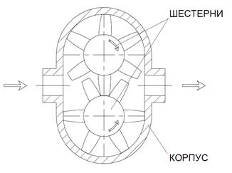
In the case of gear pumps, the role of the working chamber is played by the space limited by two adjacent gear teeth. Two gears with external or internal gearing are placed in the housing. The suction of the pumped medium into the pump occurs due to the vacuum created between the gear teeth disengaging. The fluid is carried by teeth in the pump body and then forced into the discharge port as the teeth re-engage. For the flow of the pumped medium in gear pumps, end and radial clearances are provided between the housing and the gears.
The performance of a gear pump can be calculated as follows:
Q = 2 f z n b η V
f – cross-sectional area of the space between adjacent gear teeth, m2
z – number of gear teeth
b – gear tooth length, m
n – tooth rotation frequency, sec -1
η V – volumetric efficiency
There is also an alternative formula for calculating the performance of a gear pump:
Q = 2 π D Н m b n η V
Q – gear pump capacity, m 3 /s
D Н – initial gear diameter, m
m – gear module, m
b – gear width, m
n – gear rotation speed, sec -1
η V – volumetric efficiency
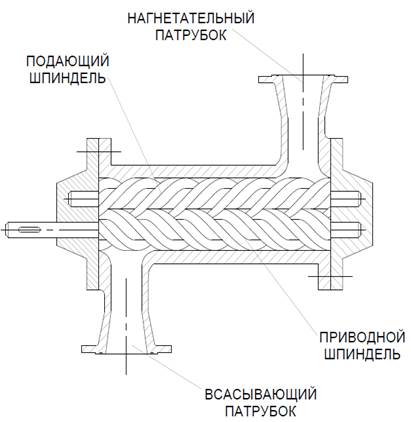
In pumps of this type, pumping of the medium is ensured by the operation of a screw (single-screw pump) or several screws in mesh in the case of multi-screw pumps. The screw profile is selected in such a way that the pump discharge area is isolated from the suction area. The screws are located in the housing in such a way that during their operation, areas filled with the pumped medium are formed confined space, limited by the profile of the screws and the housing and moving towards the discharge area.
The performance of a single screw pump can be calculated as follows:
Q = 4 e D T n η V
Q – screw pump productivity, m 3 /s
e – eccentricity, m
D – rotor screw diameter, m
T – pitch of the stator helical surface, m
n – rotor speed, sec -1
η V – volumetric efficiency
Centrifugal pumps are one of the most numerous representatives of dynamic pumps and are widely used. The working body in centrifugal pumps is a wheel mounted on a shaft, having blades enclosed between disks, and located inside a spiral housing.
Due to the rotation of the wheel, a centrifugal force is created that acts on the mass of the pumped medium located inside the wheel and transfers to it part of the kinetic energy, which then turns into potential pressure energy. The vacuum created in the wheel ensures a continuous supply of the pumped medium to their suction pipe. It is important to note that before starting operation, the centrifugal pump must be pre-filled with the pumped medium, since otherwise the suction force will not be enough for normal operation of the pump.
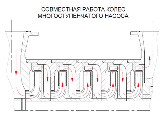
A centrifugal pump may have more than one working element, but several. In this case, the pump is called multistage. Structurally, it differs in that there are several impellers located on its shaft at once, and the liquid sequentially passes through each of them. A multistage pump with the same performance will create greater pressure in comparison with a similar single-stage pump.
The performance of a centrifugal pump can be calculated as follows:
Q = b 1 (π D 1 -δ Z) c 1 = b 2 (π D 2 -δ Z) c 2
Q – productivity of the centrifugal pump, m 3 /s
b 1.2 – wheel passage width on diameters D 1 and D 2, m
D 1.2 – outer diameter of the inlet (1) and outer diameter of the wheel (2), m
δ – blade thickness, m
Z – number of blades
C 1,2 – radial components of absolute velocities at the entrance to the wheel (1) and exit from it (2), m/s
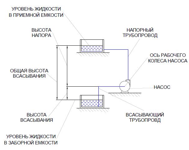
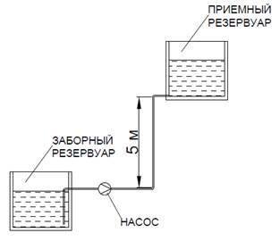
Head calculation
As noted above, pressure is not a geometric characteristic and cannot be identified with the height to which the pumped liquid must be raised. The required pressure value consists of several terms, each of which has its own physical meaning.
The general formula for calculating pressure (the diameters of the suction and discharge pipes are assumed to be the same):
H = (p 2 -p 1)/(ρ g) + H g + h p
H – head, m
p 1 – pressure in the intake tank, Pa
p 2 – pressure in the receiving tank, Pa
H g – geometric height of rise of the pumped medium, m
h p – total pressure loss, m
The first of the terms of the pressure calculation formula represents the pressure difference that must be overcome during the process of pumping liquid. There may be cases when the pressures p 1 and p 2 coincide, and the pressure created by the pump will be used to raise the liquid to a certain height and overcome resistance.
The second term reflects the geometric height to which the pumped liquid must be raised. It is important to note that when determining this value, the geometry of the pressure pipeline, which may have several ascents and descents, is not taken into account.
The third term characterizes the reduction in the generated pressure, depending on the characteristics of the pipeline through which the medium is pumped. Real pipelines will inevitably resist the flow of liquid, to overcome which it is necessary to have a supply of pressure. The total resistance consists of friction losses in the pipeline and losses in local resistances, such as turns and bends of the pipe, valves, expansion and narrowing of the passage, etc. The total pressure loss in the pipeline is calculated using the formula:
H rev – total pressure losses, consisting of friction losses in pipes H t and losses in local resistance N ms
H rev = H T + H MS = (λ l)/d e + ∑ζ MS = ((λ l)/d e + ∑ζ MS)
λ – friction coefficient
l – pipeline length, m
d E – equivalent pipeline diameter, m
w – flow speed, m/s
g – free fall acceleration, m/s 2
w 2 /(2 g) – velocity head, m
∑ζ MC – the sum of all local resistance coefficients
Calculation of pump power consumption
Several powers are allocated depending on the losses during its transmission, which are taken into account different coefficients useful action. The power that goes directly to transfer the energy of the pumped liquid is calculated by the formula:
N P = ρ g Q H
N P – useful power, W
ρ – density of the pumped medium, kg/m 3
g – free fall acceleration, m/s 2
Q – flow rate, m 3 /s
H – total head, m
The power developed on the pump shaft is greater than the useful power, and its excess goes to compensate for power losses in the pump. The relationship between useful power and shaft power is established by the pump efficiency. Pump efficiency takes into account leakage through seals and clearances (volumetric efficiency), pressure losses when the pumped medium moves inside the pump (hydraulic efficiency) and friction losses between moving parts of the pump, such as bearings and seals (mechanical efficiency).
N B = N P /η N
N V – power on the pump shaft, W
N P – useful power, W
η N – pump efficiency
In turn, the power developed by the engine exceeds the power on the shaft, which is necessary to compensate for energy losses during its transmission from the engine to the pump. Electric motor power and shaft power are related by the transmission and motor efficiencies.
N D = N V /(η P ·η D)
N D – engine power consumption, W
N V – shaft power, W
η P – transmission efficiency
η N – engine efficiency
The final installed engine power is calculated from the engine power, taking into account possible overload at the time of start-up.
N У – installed engine power, W
N D – engine power consumption, W
β –
power reserve factor
The power reserve factor can be approximately selected from the table:
Limit suction lift
(for centrifugal pump)
Suction in a centrifugal pump occurs due to the pressure difference in the vessel from which the pumped medium is taken and on the impeller blades. An excessive increase in the pressure difference can lead to the appearance of cavitation - a process in which the pressure decreases to a value at which the boiling point of the liquid drops below the temperature of the pumped medium and its evaporation begins in the flow space with the formation of many bubbles. The bubbles are carried away by the flow further along the flow, where under the influence of increasing pressure they condense and “collapse” occurs, accompanied by numerous hydraulic shocks, which negatively affect the service life of the pump. In order to avoid the negative effects of cavitation, it is necessary to limit the suction height of the centrifugal pump.
The geometric suction lift can be determined by the formula:
h g = (P 0 -P 1)/(ρ g) – h St – w²/(2 g) – σ H
h Г – geometric suction height, m
P 0 – pressure in the intake tank, Pa
P 1 – pressure on the impeller blades, Pa
ρ – density of the pumped medium, kg/m 3
g – free fall acceleration, m/s 2
h St – losses to overcome hydraulic resistance in the suction pipeline, m
w²/(2 g) – velocity pressure in the suction pipeline, m
σ·H – losses due to additional resistance, proportional to pressure, m
where σ is the cavitation coefficient, H is the pressure created by the pump
The cavitation coefficient can be calculated using the empirical formula:
σ = [(n √Q) / (126H 4/3)] 4/3
σ – cavitation coefficient
n – impeller rotation speed, sec -1
Q – pump capacity, m 3 /s
N – generated pressure, m
There is also a formula for centrifugal pumps to calculate the head reserve ensuring the absence of cavitation:
H sq = 0.3 (Q n²) 2/3
H kv – head reserve, m
Q – productivity of the centrifugal pump, m 3 /s
n – impeller rotation speed, s -1
Examples of problems for calculating and selecting pumps with solutions
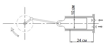
Example No. 1
A single-action plunger pump provides a pumped medium flow rate of 1 m 3 /h. The diameter of the plunger is 10 cm, and the stroke length is 24 cm. The rotation speed of the working shaft is 40 rpm.
It is required to find the volumetric efficiency of the pump.
Plunger cross-sectional area:
F = (π d²)/4 = (3.14 0.1²)/4 = 0.00785 m²2
Let us express the efficiency from the formula for the flow rate of a plunger pump:
η V = Q/(F S n) = 1/(0.00785 0.24 40) 60/3600 = 0.88
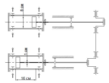
Example No. 2
A two-piston, double-action pump creates a head of 160 m when pumping oil with a density of 920 kg/m 3 . The piston diameter is 8 cm, the rod diameter is 1 cm, and the piston stroke length is 16 cm. The rotation speed of the working shaft is 85 rpm. Need to calculate required power electric motor (the efficiency of the pump and electric motor is 0.95, and the setting factor is 1.1).
Cross-sectional areas of the piston and rod:
F = (3.14·0.08²)/4 = 0.005024 m²
F = (3.14·0.01²)/4 = 0.0000785 m²
The pump performance is determined by the formula:
Q = N (2F-f) S n = 2 (2 0.005024-0.0000785) 0.16 85/60 = 0.0045195 m³/hour
N P = 920 9.81 0.0045195 160 = 6526.3 W
Taking into account the efficiency and installation coefficient, we obtain the final installed power:
N UST = 6526.3/(0.95 0.95) 1.1 = 7954.5 W = 7.95 kW
Example No. 3
A three-piston pump will pump a liquid with a density of 1080 kg/m 3 from an open container into a vessel under a pressure of 1.6 bar with a flow rate of 2.2 m 3 /hour. The geometric height of the liquid rise is 3.2 meters. The useful power consumed for pumping liquid is 4 kW. It is necessary to find the amount of pressure loss.
Let's find the pressure created by the pump from the useful power formula:
H = N P /(ρ g Q) = 4000/(1080 9.81 2.2) 3600 = 617.8 m
Let's substitute the found pressure value into the pressure formula, expressed in terms of the pressure difference, and find the required value:
h p = H – (p 2 -p 1)/(ρ g) – H g = 617.8 – ((1.6-1) 10 5)/(1080 9.81) – 3.2 = 69.6 m
Example No. 4
The actual productivity of the screw pump is 1.6 m 3 /hour. Geometric characteristics of the pump: eccentricity – 2 cm; rotor diameter – 7 cm; The pitch of the rotor helical surface is 14 cm. The rotor speed is 15 rpm. It is necessary to determine the volumetric efficiency of the pump.
Let us express the required value from the formula for the productivity of a screw pump:
η V = Q/(4 e D T n) = 1.6/(4 0.02 0.07 0.14 15) 60/3600 = 0.85
Example No. 5
It is necessary to calculate the pressure, flow rate and net power of a centrifugal pump pumping liquid (low viscosity) with a density of 1020 kg/m 3 from a tank with overpressure 1.2 bar and a tank with an excess pressure of 2.5 bar through a given pipeline with a pipe diameter of 20 cm. The total length of the pipeline (together with the equivalent length of local resistance) is 78 meters (assuming the friction coefficient is 0.032). The height difference between the tanks is 8 meters.
![]()
For low-viscosity media, we select the optimal speed of movement in the pipeline equal to 2 m/s. Let's calculate the fluid flow through a given pipeline:
Q = (π d²) / 4 w = (3.14 0.2²) / 4 2 = 0.0628 m³/s
Velocity pressure in the pipe:
w²/(2 g) = 2²/(2 9.81) = 0.204 m
With an appropriate speed pressure, friction losses m local resistance will be:
H T = (λ l)/d e = (0.032 78)/0.2 0.204 = 2.54 m
The total pressure will be:
H = (p 2 -p 1)/(ρ g) + H g + h p = ((2.5-1.2) 10 5)/(1020 9.81) + 8 + 2.54 = 23.53 m
It remains to determine the useful power:
N P = ρ g Q H = 1020 9.81 0.0628 23.53 = 14786 W
Example No. 6
Is it advisable to pump water with a centrifugal pump with a capacity of 50 m 3 /hour through a pipeline 150x4.5 mm?
Let's calculate the speed of water flow in the pipeline:
Q = (π d²)/4 w
w = (4 Q)/(π d²) = (4 50)/(3.14 0.141²) 1/3600 = 0.89 m/s
For water, the flow speed in the discharge pipeline is 1.5 - 3 m/s. The resulting flow rate value does not fall within this interval, from which we can conclude that the use of this centrifugal pump is impractical.
Example No. 7
Determine the feed ratio of the gear pump. Geometric characteristics of the pump: cross-sectional area of the space between the gear teeth 720 mm 2; number of teeth 10; gear tooth length 38 mm. The rotation speed is 280 rpm. The actual flow rate of the gear pump is 1.8 m3/hour.
Theoretical pump performance:
Q = 2 f z n b = 2 720 10 0.38 280 1/(3600 10 6) = 0.0004256 m³/hour
The feed coefficient is correspondingly equal to:
η V = 0.0004256/1.8 3600 = 0.85
Example No. 8
A pump with an efficiency of 0.78 pumps liquid with a density of 1030 kg/m 3 with a flow rate of 132 m 3 /hour. The pressure created in the pipeline is 17.2 m. The pump is driven by an electric motor with a power of 9.5 kW and an efficiency of 0.95. It is necessary to determine whether the pump meets the starting torque requirements.
Let's calculate the useful power that goes directly to pumping the medium:
N P = ρ g Q H = 1030 9.81 132/3600 17.2 = 6372 W
Let's take into account the efficiency of the pump and the electric motor and determine the total required power of the electric motor:
N D = N P /(η N ·η D) = 6372/(0.78·0.95) = 8599 W
Since we know the installed power of the engine, we determine the power reserve factor of the electric motor:
β = N U / N D = 9500/8599 = 1.105
For engines with power from 5 to 50 kW, it is recommended to remove the starting power reserve from 1.2 to 1.15. The value we obtained does not fall within this interval, from which we can conclude that when operating this pump under the given conditions, problems may arise at the time of its start-up.
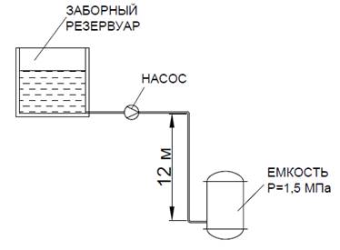
Example No. 9
A centrifugal pump pumps liquid with a density of 1130 kg/m 3 from an open reservoir into a reactor with an operating pressure of 1.5 bar with a flow rate of 5.6 m 3 /hour. The geometric height difference is 12 m, with the reactor located below the tank. The head loss due to friction in pipes and local resistance is 32.6 m. It is necessary to determine the useful power of the pump.
Let's calculate the pressure created by the pump in the pipeline:
H = (p 2 -p 1)/(ρ g) + H g + h p = ((1.5-1) 10 5)/(1130 9.81) – 12 + 32.6 = 25 .11 m
The useful power of the pump can be found using the formula:
N P = ρ g Q H = 1130 9.81 5.6/3600 25.11 = 433 W
Example No. 10
Determine the maximum increase in the flow rate of a pump pumping water (density taken equal to 1000 kg/m3) from an open tank to another open tank with a flow rate of 24 m3/hour. The geometric height of the liquid rise is 5 m. Water is pumped through 40x5 mm pipes. The electric motor power is 1 kW. The overall efficiency of the installation is assumed to be 0.83. The total pressure loss due to friction in pipes and local resistances is 9.7 m.
Let us determine the maximum flow rate corresponding to the maximum possible useful power developed by the pump. To do this, we first define several intermediate parameters.
Let's calculate the pressure required to pump water:
H = (p 2 -p 1)/(ρ g) + H g + h p = ((1-1) 10 5)/(1000 9.81) + 5 + 9.7 = 14.7 m
Net power developed by the pump:
N P = N total /η N = 1000/0.83 = 1205 W
Meaning maximum flow we find from the formula:
N P = ρ g Q H
Let's find the required value:
Q max = N P /(ρ g H) = 1205/(1000 9.81 14.7) = 0.00836 m³/s
Water flow can be increased by a maximum of 1.254 times without violating the operating requirements of the pump.
Q max /Q = 0.00836/24 3600 = 1.254
The scope of use of industrial pumping equipment is very wide. In fact, an industrial pump is used in any production area where it is necessary to transport liquid, bulk and viscous materials over long distances. Therefore, such an installation is in demand in the oil production, chemical, food, engineering fields of production, as well as in agriculture.
Industrial pumps differ from domestic versions in higher performance characteristics, and as a result, in design solutions. The specifics of each individual type of equipment depend on individual conditions use of the unit.
1 Types of industrial pumps
Various manufacturers supply the market with a huge number of variations of pumps and pumping equipment. And if there are no problems when purchasing an industrial water pump, then searching for a device to work with chemicals and thick fractions can become an overwhelming task. After all, highly specialized industrial pumps are practically never produced, and universal models are not always suitable for each specific type of pumped substance.
In this regard, much depends on the scope of application of the device and the main design aspects of the model. Based on these two characteristics, the following types of industrial pumps are distinguished:
- centrifugal;
- gear;
- screw;
- barrels;
- diaphragm.
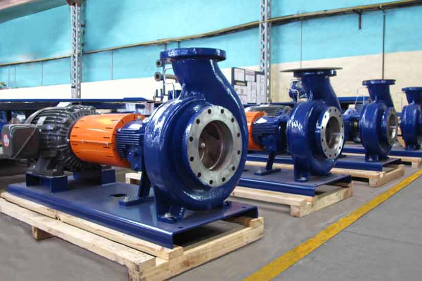
1.1 Features of centrifugal industrial plants
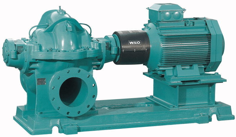
Industrial centrifugal pumps are mainly used for pumping cold or hot water inside thermal and water mains. The same principle is used during operation by industrial drainage pumps, with the help of which water is drained from pits, mines and open reservoirs. This segment of units is most often used in production, and industrial high-pressure pumps also operate on its basis.
The basis for such units is the working chamber, in which a wheel with an impeller is located, welded onto the rotor. When power is supplied to the electric pump, the motor drives the rotor. The impeller begins to rotate along with the shaft. At the same time, the blades take up the liquid and begin to rotate it in a circle at high speed. As a result, under the influence of centrifugal force, an area of rarefied air is formed at the inlet of the device, and water is sucked in, forming near the pressure pipe. high pressure and pressure is created.
A standard centrifugal pump has this design. There are also modified versions of the devices. So, according to the type of working body, water pumps of this type are divided into:
- single-stage with one impeller;
- two-stage with two wheels and two diffusers;
- multi-stage with several wheels.
More wheels provide greater productivity model, at the same time, electricity consumption increases.
Regarding the design of the impeller, centrifugal options with a closed and open impeller are distinguished. Distribution is also carried out in terms of supplying liquid to the working chamber. In this case, devices with one-way inlet and two-way start are distinguished.
The scope of application of the model also depends on the design of the shaft and its location. Industrial models with a horizontal rotor orientation are mainly installed in water supply pumps. These design options provide fluid flow rates from 50 to 270 cubic meters. m/hour and pressure up to 100 m.
A vertically oriented shaft is usually installed in drainage pumps for water. Industrial submersible pumps This type is used for pumping heavily contaminated sources. They are made of steel or reinforced cast iron. At the same time, the design of the impeller and powerful engine allow the passage of liquid containing solid parts with a diameter of over 100 mm. Moreover, the average productivity for such units is over 50 cubic meters. m/hour.
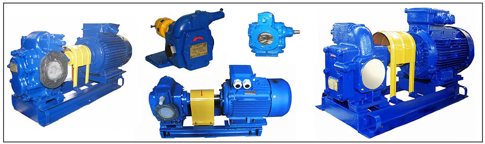
1.2 Design and principle of operation of gear devices
With the help of industrial pumps and units of this type, both liquid and viscous high-temperature substances are transported. Such a pump consists of two or more gears, which are located inside the working chamber. One of the gears is the drive. It is installed on a shaft coming from the motor. The second gear is the driven one. It is mounted on a metal rod using a bushing and is driven by the drive. The opening between the working compartment and the engine is hermetically sealed using graphite seals.
The operating principle of such a device is as follows:
- the wheels rotate in different directions, upward from the inlet;
- with the help of teeth (straight, oblique or chevron) water is taken from the tasty pipe and transported upward in the resulting closed cavities;
- in the area of the pressure pipe, as a result of constant supply, high pressure is formed and, as a result, the supply of liquid into the pipeline.
As a result of the operation of such gears, a continuous supply of fluid is formed. The only disadvantage of such devices is increased sensitivity to solid impurities that harm the nodes.
An overview of the main operating characteristics includes the following values:
- productivity from 60 to 380 cubic meters. m/hour;
- the temperature of the pumped medium is from -40 to +480 degrees;
- viscosity up to 1,000,000 cSt.
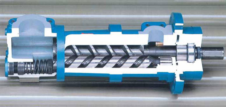
1.3 Industrial screw units
Screw devices are used for various industries. They are used in the mining, engineering, oil refining, and food industries. Many pumps for the chemical industry are built on the same operating principle.
Among the main advantages of this pump are high pressure characteristics and continuous flow. Also, using such devices you can work with thick substances, as well as liquids containing a high percentage of abrasive impurities.
As a rule, screw units have a cylindrical design. The basis of such devices is a metal screw, which rotates from the engine, and a rubber stator. During rotation, the rotor spiral comes into contact with the surface of the stator, forming temporary sealed chambers. It is in these chambers that the pumped medium is transported to the outlet.
In terms of use, screw pumps and equipment are divided into horizontal and vertical. Horizontal ones are more designed for working with thick materials. They are installed on anti-vibration pads or a special base. By using vertical options Mineral and salt water is extracted from wells. This segment is represented by industrial deep well pumps, designed for deep sources.
The submersible and surface version of the screw pump are capable of providing liquid flow in the range from 50 to 1700 cubic meters. m/hour. The device is suitable for working with liquids whose temperature reaches 180 degrees. The operating pressure of the device is 24 bar.
A wide range of industrial screw pumping equipment is also produced in Russia. The main Russian supplier of screw units is AMC. Also popular brands in the Russian Federation are ENCE Engineering, VIP Technology, LAKKK.
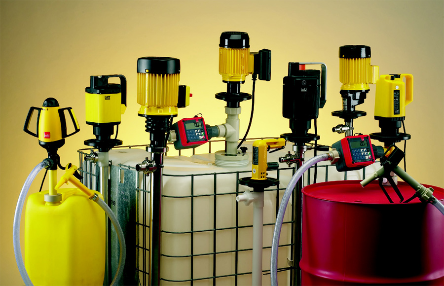
1.4 Barrel pumping devices
Barrel units are used mainly in the chemical industry. With the help of such devices, alkali, acids and other aggressive substances are pumped. The main task Such models involve pumping liquid from one container to another, or cleaning individual reservoirs. A wide range of such devices allows you to select equipment for each type of source.
Devices of this type are made of chemically neutral polymer compounds or alloy steel. In most cases, they are compact in size for more easy installation pumping equipment.
Some models of barrel pumps are manufactured in explosion-proof housings. At the same time, the transition from the engine to the working chamber is protected by a special magnetic coupling, which seals the engine compartment as tightly as possible.
In terms of the design of the working body, barrel pumps are:
2 Characteristics of industrial diaphragm pumps
Diaphragm devices are a volumetric type of device. According to the principle of operation, such units are similar to piston devices. The difference is that instead of a piston, a flexible membrane is used.
During engine operation, it moves a metal rod, on the edge of which a diaphragm is fixed. When the diaphragm bends, a vacuum is formed in the working chamber, due to which liquid is sucked through the pump nozzle. In the next phase of movement of the membrane, it returns to its original position, due to which the liquid is pushed out into the pipeline.
Many industrial pumps are made in the form of two-chamber devices. In this case, the engine drives two oppositely placed chambers at once. At the same time, the moving membrane complements the other, providing a more even flow and high performance. The main materials from which membrane devices are made are plastic, cast iron, steel or aluminum-based alloys.
The main advantages of diaphragm industrial models are versatility and performance. This device is suitable for all types of substances: aggressive chemicals, thick materials, materials with a high content of suspended solids. Also, the type features simplicity of design, which facilitates the repair of pumping equipment.
2.1 Calpeda pumping equipment (video)
The official online store "PedrolloPump" offers low prices on Pedrollo pumps for wells, wells and septic tanks. The assortment includes more than ten categories of equipment Italian manufacturer, available for shipment from a warehouse in Moscow. The products are certified and meet international and Russian standards.
Before you buy a Pedrollo pump, you can read the full technical specifications of the product on the website or get qualified advice from a manager. We will answer your questions and select the optimal equipment package. If necessary, you can order components and accessories for any model.
Catalog:
Over ten years on the market - thousands of clients throughout the country
The main activity of the company is retail supplies of equipment. You can buy a Pedrollo pump in Moscow from any city in Russia. Our own transport service and cooperation with leading carrier companies allows us to ship orders to all regions. Call our managers to discuss all questions regarding the delivery of goods.
Why is it profitable to work with us? It is worth buying Pedrollo pumps in Moscow in our online store for several reasons:
- The company sells equipment as an official dealer. This means that you receive not only complete information and technical support, but also warranty service, as well as the ability to order original spare parts for repairs.
- Low prices. Dealer status allows the company to set favorable prices for customers. Pedrollo pumps for water and other liquids are cheaper than in many retail stores. The cost of products is transparent - the price list shows the final prices for the products. You can find the price list on our website.
- Wide range of products. The catalog presents all the manufacturer's products in full configuration. In addition to the main equipment, the company supplies engines, electronic pressure regulators, and other components. Always in stock - Pedrollo deep-well pumps, which are in great demand.
The company's advantages include its extensive experience in the market. We have been working for more than ten years, during which time we have entered into supply agreements with thousands of clients from different regions. We cooperate with private clients, enterprises, utility organizations, and representatives of agriculture.
To buy a Pedrollo pump in Moscow, you can visit specialized exhibitions - we regularly participate in such events. This provides additional experience for both the company and its employees.
Call us or place an order on the website - all equipment from the catalog is in stock and ready to ship, and the price for the Pedrollo pump will always be favorable.
The technical characteristics of industrial units are not comparable with the power of household pumping equipment, and this is natural. General classification includes at least seventy types and subtypes of pumps.
Which of them are capable of developing such power to satisfy the needs of large-scale production, or to provide water supply to a metropolis? And in general, what are industrial high-pressure pumps?
The instructions we offer will tell you about this, as well as the video in this article.
What water units are used in production?
Technological processes of many industries, one way or another, are associated with water or other liquids that also need to be pumped.
Much, if not everything, depends on the reliability of the pumping equipment involved in the work. Therefore, its selection is made according to calculations and actual operating conditions.
- Note that in our country there are many enterprises specializing in the manufacture of industrial units. In many industries and industries, domestic equipment is used, and this has many advantages. Firstly, their quality is in no way inferior to their imported counterparts.
- Secondly, the price of any product produced in its own country is always lower, since transport costs are reduced. And also, in the event of a breakdown, you can easily order and deliver a replacement spare part (see), or, if necessary, invite a competent representative from the factory.
- Only Chinese-made pumps can compete with domestic equipment in terms of cost, but there is no particular confidence in their quality. So, characterizing industrial high-pressure pumps - at least as far as markings and symbols, we will rely on the standards adopted in our country.
- All existing pumps, based on the type of working chamber, as well as its connections with the inlet and outlet, are divided into two groups: volumetric and dynamic. In volumetric units, fluid movement is ensured by periodic changes in the volume of the chamber - hence the name. That is, the mechanism of such a pump is based on reciprocating motion.
- We will not talk about this equipment in more detail, since it is not used for water. Almost all positive displacement pumps are industrial, but their main purpose is pumping viscous liquids. They are used in the oil and pharmaceutical industries, in some food and chemical industries.
As for dynamic equipment, its operating principle is based on the conversion of one type of energy into another. For water this is perfect option: due to the number of working bodies and the speed of their rotation, as well as the arrangement of several pumps, it is possible to create a unit of arbitrarily large power.
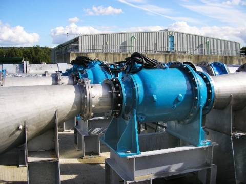
Axial pumps
The group is divided into three subgroups, in each of which different forces act on the liquid. These include electromagnetic pumping equipment, friction pumps, and vane pumps.
It is the last subgroup that includes axial units, which are most often manufactured in an industrial version.
- They can have rigidly fixed blades, or they can be rotary-bladed. Regardless of this, the water in the chamber moves in the direction of its axis, which is the main feature of axial pumps. By the way, in pumps with rotating blades, thanks to the ability to change the angle of their installation, it is possible to regulate the performance and pressure on a larger scale.
- Such pumps are marked “O” and “OP”. IN powerful units for industrial purposes, water is discharged from the working chamber at an angle of 60 degrees, whereas in small pumps, the discharge angle is straight. Rotary units have one more feature: the pump shaft is hollow, and inside it there is a rod that fixes the movement mechanism of the blades.
- This mechanism can be operated manually, hydraulically, or electrically. We think it is needless to say that changing the position of the blades is carried out only if the pump is turned off. Axial pumps are usually designed for high flow at low head. Imagine that their productivity can exceed 120,000 m3/hour!
- Units with an axial design differ favorably from centrifugal equipment in that they can pump not only clean water, but also liquids with a certain degree of contamination. There is one more advantage: with a similar speed coefficient, taking into account three main parameters (pressure, flow, wheel speed), the dimensions and weight of the pump will be smaller.
- Axial pumps are used where high pressure is not needed, but significant water consumption is expected. In water supply systems these are first lift stations, in land reclamation these are irrigation installations. They are also used in sewer and drainage systems, wastewater treatment plants, in construction dewatering.
- According to the type of housing, axial pumps can be vertical (OV), horizontal, capsule type, and submersible. Vertical units, including rotary units (OPV), are used at nuclear and thermal power plants, in agriculture, and also for pumping sea water.
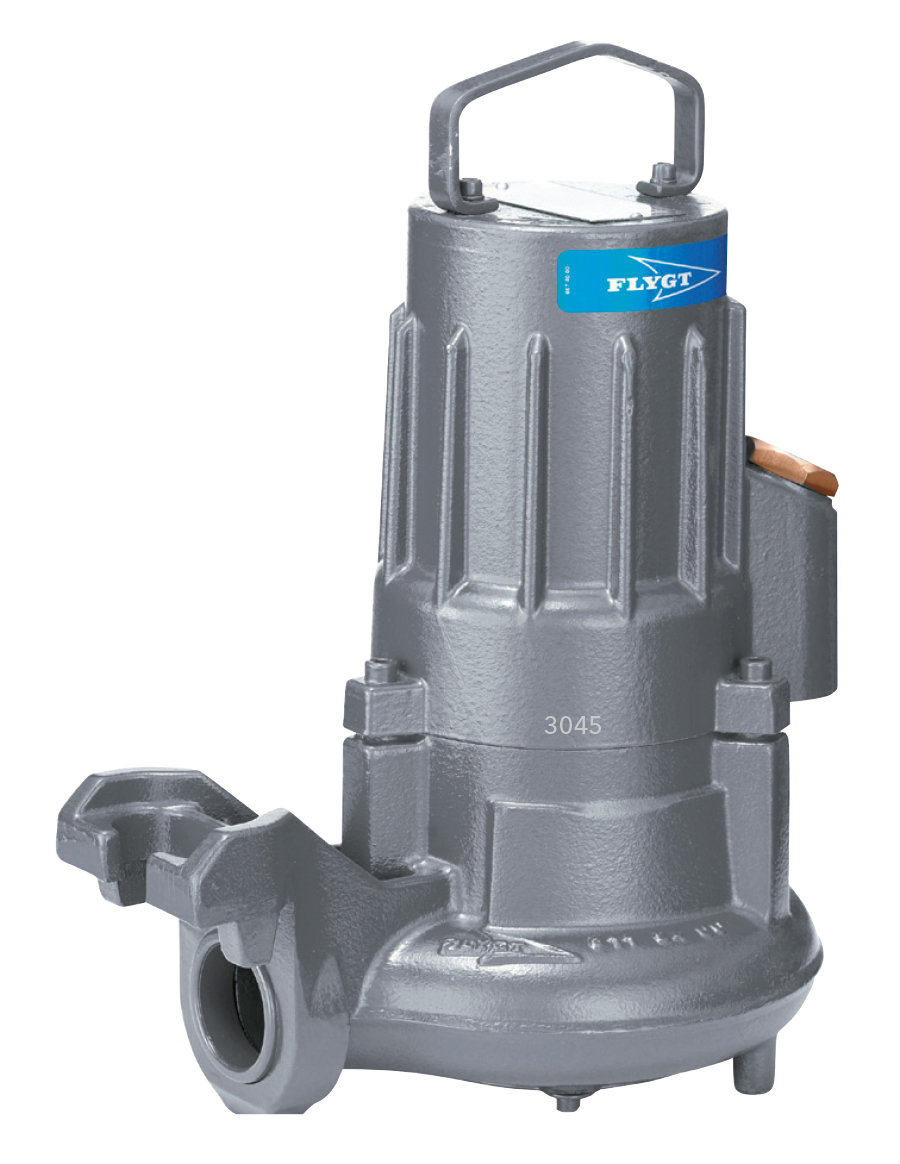
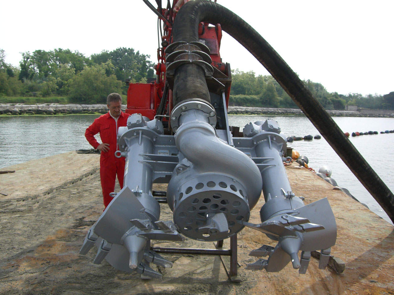
- Large, high-power pumps most often have an axial supply. In this case, the working chamber and the engine of the unit, although they are in the same plane, are installed on different foundations. As a rule, all fecal pumps do this - and this applies to both vertical and horizontal modifications.
As for submersible models, they are usually monoblock. That is, both the working chamber and the motor, although not always located in a common housing, are a single unit. You can see this version of the pump in the photo above.
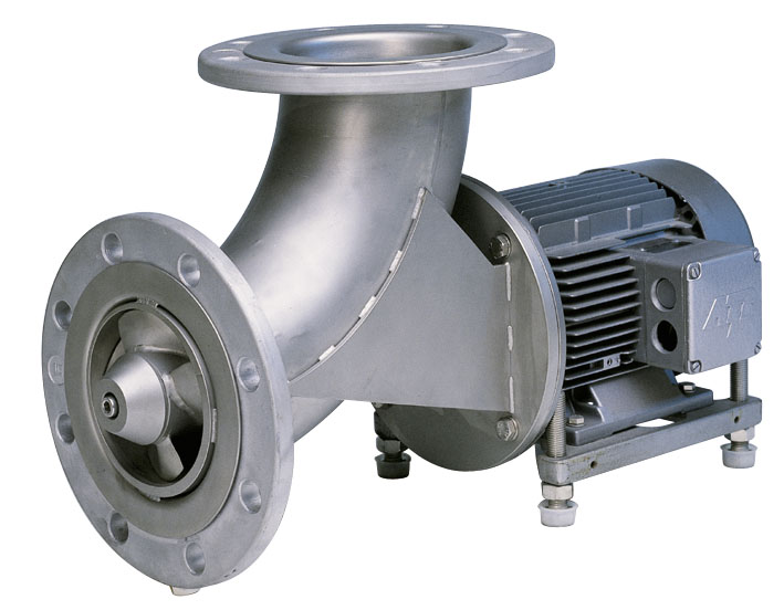
Centrifugal units on an industrial scale
They also refer to bladed equipment, and differ from the previous version only in the direction of water movement.
In this case, it does not move at an angle to the wheel axis, but along it. Moreover, the shaft rotates in one direction, and the water ring in the other.
- This operating principle allows you to significantly increase water pressure, especially in those models that have a multi-stage design. Therefore, centrifugal pumps are used where it is necessary to create high pressure in the pipeline. First of all, these are stations of the second and subsequent rises - in water supply, sewerage and fire extinguishing systems. Also, this circulation pumps for heating systems.
- According to the type of housing, centrifugal pumps are also vertical and horizontal, and can be surface or submersible. Two more categories should be distinguished. These are models designed for Wastewater, and so-called soil pumps, which are used for pumping hydraulic mixtures.
- The last option differs from other units in the design of the entrance: it can be axial or lateral. Distinctive feature ground and is the fact that they are all equipped with a flushing system that allows you to eliminate blockages.
- These pumps have high power, and are capable of not only lifting liquefied soil, for example, from a deep mine, but also transporting it over quite significant distances. Such equipment operating conditions are not at all the same as supplying clean water from the well. Therefore, in the manufacture of working parts and seals for these pumps, the most durable metals and alloys, composites and reinforced rubber.
Soil, sand and are used in the mining and processing industry, in the development of oil fields, drilling deep artesian wells, in some industries, and in construction. They are designed for high content abrasive impurities in water, and this figure can reach more than 1200 kg per 1 m3 of water.
Features of installation of industrial pumps
As you can see, and specifications, and operating conditions for pumping equipment are completely different. Therefore, it is simply impossible to generalize the process of installation and commissioning of an industrial pump. But there is undoubtedly something in common.
All units are delivered to the consumer assembled, complete with a control cabinet, instrumentation and connecting fittings. Before installation, electricians and mechanics can only carry out an inspection to ensure compliance with the declared configuration and check the functionality of the mechanism.
Foundation for the unit
Depending on the dimensions and purpose of the pump, a special foundation is placed under it, reinforced concrete slab, or a frame is welded from a steel channel.
As for the frame, by agreement with the customer, it can be supplied by the factory along with the unit.
- Attach such a frame to monolithic foundation, poured specifically for this purpose. And, by the way, the process of producing these works must comply with building codes. In this case, this is SNiP 2.02.05*87 - it regulates the construction of foundations for machines that create dynamic loads. Their category also includes pumping units.
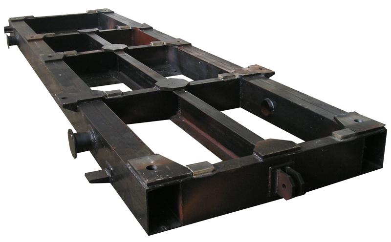
- During the process of pouring the foundation, anchor bolts are embedded in the thickness of the concrete, with the help of which the metal support for the unit is rigidly secured. The length of the anchors can be up to 70 cm, and they usually come with the frame if it is manufactured at the factory.
- When the pump is not monoblock, there are standard places on the frame intended for installing the pump itself and its motor. As mentioned earlier, there are options for pumps whose motor must be installed on a separate frame. Then, accordingly, two foundations are built.
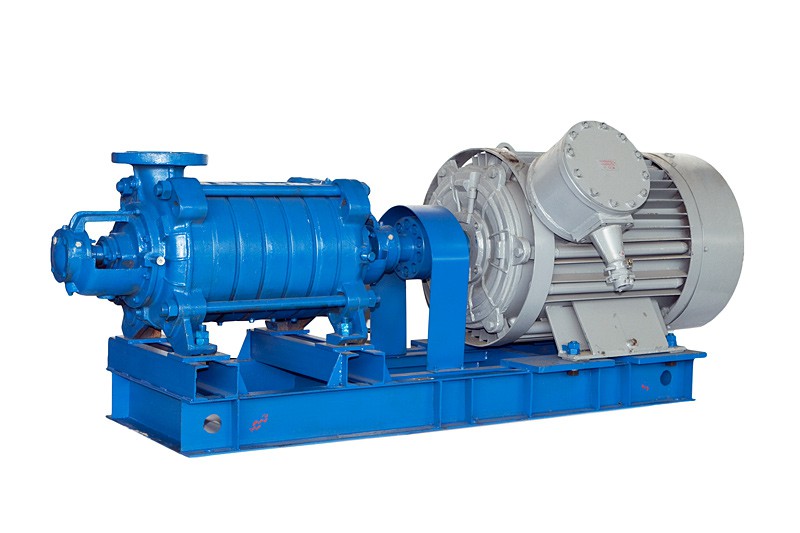
- After the frame is installed, the correctness of its position is verified using a level. After that, the anchor bolts located in the well-shaped holes are tightened and then filled with concrete. This fastening provides a 100% guarantee that it will not loosen over time.
Then they begin to install the engine and pump, also leveling their spatial position, after which their shafts are aligned. To protect against the ingress of oils, the concrete foundation is primed with liquid cement mortar with the addition of red lead, and then, just like the frame, they are painted.
Introduction of a pump into a water supply system
A pump, or an installation that combines several pumps into one enlarged unit, is located in a specially designated capital room or pavilion.
It depends on the purpose of the equipment and the dimensions:
- If it's tap water or heating system, the installation location can be a boiler room, a heating point, or a boiler room. Let's say, in production, the pump must be installed directly in the workshop where water supply is required. In this case, a fence is simply installed around the perimeter of the pump foundation, which must have a height of at least 20 cm.
- Since people work in the workshops, measures have to be taken to soundproof the unit. Including, it is necessary to reduce, or better yet, reduce vibration to zero. It is known to be capable of destroying any, even the most reliable mechanism. Typically, these problems are solved with the help of shock-absorbing mounts for equipment and special flexible inserts for pipelines.
- After graduation installation work, including the laying of pipelines, the system is tested and accepted, which is documented in the appropriate act. First, a hydraulic test is carried out, and then a pneumatic test to detect defects made during installation.
In this case, plugs (inventory plugs) must be installed at the ends of the pipelines. IN circulation systems The uniform heating of all pipeline elements is checked. And only after successfully completed tests, the plugs are removed and the pressure pipeline is inserted into the collector.
Pump characteristics usually mean the relationship between the technical parameters of the unit - pressure, power, efficiency, pressure, flow and suction height at different conditions work. This takes into account the rotation speed of the impeller and the consistency of the pumped liquid at the inlet and outlet.
The characteristics of a centrifugal pump depend on its design, the materials from which the parts are made, as well as on the principle of operation of the main components.
The most accurate pump characteristics are determined experimentally in the factory. It happens that characteristics are indicated theoretically based on calculations, but in this case, real data may differ from those expected. When operating centrifugal pumps, it is taken into account a large number of external factors that are not always possible to foresee, therefore the characteristics obtained theoretically have a certain percentage of inaccuracy.
Tests that determine the characteristics of a centrifugal pump are carried out in accordance with state standards. In this case, the pump is equipped with measuring instruments that record the readings of the unit during startup. In our catalog, industrial water pumps are presented in a wide range.
In the documentation for a centrifugal pump, the characteristic is usually presented in the form of a graph with several curves and is indicated next to technical parameters. On such graphs you can trace the dependence of suction height on flow, pressure on power, efficiency on pressure and get acquainted with other characteristics. The centrifugal cantilever pump is designed for pumping clean water (except sea water) with pH=6-9 under stationary conditions.
Operating principle of centrifugal pumps
Centrifugal pumps can only operate if the device body is filled with water. As the name suggests, these pumps operate under the influence of centrifugal force caused by rotating wheels.
The pump housing contains one or more impellers firmly attached to the shaft. The impeller is equipped with curved blades, where the liquid enters through the suction pipe. When the unit starts, a shaft connected to an electric motor drives a wheel, which captures liquid with blades and throws it from the center to the inner walls of the housing. The developed centrifugal force moves the liquid to the discharge pipeline through the guide chamber. Thus, with the space between the blades freed up, the pressure decreases, which makes it possible to accept newly incoming liquid from the suction pipeline. Typically, the suction pipe is equipped with a filter element that prevents solid particles and debris from entering the housing.
Depending on the number of impellers, centrifugal pumps can be of a single-stage or multi-stage design, but the principle of their operation remains almost the same. The difference is that in multi-stage units, the fluid pressure increases at each subsequent wheel.
Multipumps Group of Companies offers a large selection of pumping equipment.


