For fire safety Fire safety devices must be installed in the room. These are not empty requirements, these are fire protection measures. The installation of fire detectors itself different types refers to a complex of specialized works. They are carried out in accordance with established norms and regulations. All requirements are specified in the thematic documentation of the Ministry of Emergency Situations. It is important to remember that installation and further maintenance must be carried out by companies that are licensed to carry out these activities.
How smoke detectors are installed
To determine how many smoke detectors are needed for a particular room, consider the following:
- Determine the total area of the room;
- Consider the possible monitored area for one sensor.
There are certain rules for installing smoke alarms. Sensors must be installed under the ceiling. If for some reason arrangement in this way is impossible, then columns are used, and devices are already installed on them. In addition to columns, walls and other load-bearing structures are allowed.
The documents do not specify the specific location of smoke fire detectors, but only indicate the distances from partitions and to corners in the room. Therefore, they are usually installed in those places where the area will be covered to the maximum.
The documents indicate the necessary distances required when installing point smoke devices from ceilings to corners. They are as follows:
- Under the ceiling, the sensors are installed at a distance of at least 10 cm from the wall;
- If installation takes place on columns or partitions, then the distance should be 10-30 cm (including the dimensions of the device) from the ceiling to the corner.
If linear fire detectors are installed, then the rules are slightly different. They must be installed on partitions or columns so that the optical axis at the receiver and source is at least 10 cm from the ceilings. In this case, it must be taken into account that both the emitter and the receiver must be placed on the structure in such a way that during operation other objects do not fall into the fire hazard detection zone. Otherwise they may cross the optical axis.
There are standards for installing fire detectors. Optical smoke devices are positioned so that the distance between the optical axis and objects is at least 50 cm. This is the only way to avoid any interference and at the same time there will be no obstacles to detecting a fire.
How to install manual fire call points
This type is intended for autonomous detection of fire sources. Powered by people. There are special installation rules. They depend on the type of device and the room where the installation will take place.
According to the requirements, manual call points are installed in places far from electrical or permanent magnets. They should not be placed near electrical appliances that create magnetic fields. Because of this, disturbances in the operation of the detector mechanism and involuntary activation are possible in the future if it is suddenly activated.
If the installation of hand-held sensors takes place in public or administrative buildings, where there are always a large number of people, then they should be installed in the following places:
- In the halls;
- In the corridors;
- In the lobbies;
- On staircase landings;
- Near all exits from the building.
If the installation of fire detectors takes place in cable structures (type - tunnels), then the installation should be near their entrance, at branches, emergency exits. It is important to remember to always have free access to the device.
How to install autonomous fire detectors
Before installation, you need to find out how many sensors should be in one room. Usually the quantity is calculated taking into account that one device is installed per 30 sq.m. area. But the meaning may be different if the technical data sheet contains other indicators. They may be more or less.
Typically, autonomous detectors are installed on the ceiling. If installation work cannot be done, then install them on a column or wall. But the following distances must be taken into account:
- The sensor should be located no more than 30 cm from the ceiling;
- The uppermost element of the device should be located at a distance of about 10 cm from the ceiling;
- Sensors should not be installed in a corner of the room.
Sometimes it happens that ceiling structures are broken into separate parts. In such a situation, autonomous sensors are installed in each compartment. If there are protruding parts on the ceiling and their height is more than 8 cm, then the maximum monitored area of one sensor should be reduced by 25 percent.
There is no general standard regarding the installation height of fire detectors. But if some requirements. If the ceilings are multi-tiered and the height of some is more than 40 cm and the area is more than 0.75 sq.m, then it is necessary to install separate autonomous devices for detecting fires.
Fire detectors should not be installed in areas where there is constant exposure to Sun rays. A place near the supply ventilation system would be unsuitable. At the venue installation work An air flow speed of more than 1 m/s is not allowed.
Requirements for the placement of fire detectors are given in NPB 88-2001* “Fire extinguishing and alarm installations. Design norms and rules." However, this document regulates only the basic options for placing detectors for relatively simple cases. In practice, there are often rooms with sloping ceilings, decorative suspended lattice ceilings, exhaust ventilation etc., which must be properly protected, despite the lack of specific instructions in NPB 88-2001*. For all non-standard cases, there is a general requirement in clause 3. NPB 110-03 “List of buildings, structures, premises and equipment subject to protection by automatic fire extinguishing installations and automatic fire alarms”: “Type of automatic extinguishing installation, extinguishing method, type of fire extinguishing agents, type of plant equipment fire automatics determined by the design organization depending on the technological, structural and space-planning features of the protected buildings and premises, taking into account the requirements of current regulatory and technical documents.” NPB 88-2001* also contains General requirements, for example, according to clause 12.19, “the placement of point heat and smoke fire detectors should be made taking into account the air flows in the protected room caused by supply or exhaust ventilation,” however, criteria for optimizing the location of detectors are not given, it is only stated that “in this case, the distance from the detector before vent must be at least 1 m."
You can avoid gross design errors in many complex cases by using Additional materials, for example, the European Standard BS 5839-1:2002 on Fire Detection and Alarm Systems for Buildings, Part 1: Code of Practice for the Design, Installation and Maintenance of Systems, where each section and paragraph first sets out the physical processes and then requirements arising from them, which allows you to be confident in the correctness of the chosen solution in a particular case. For example, when arranging automatic fire detectors, it is necessary to take into account the specifics of their operation depending on the type:
“The operation of heat and smoke detectors depends on convection, which carries hot gas and smoke from the fire to the detector. The location and installation step of these sensors should be based on the need to limit the time spent on this movement and provided there is a sufficient concentration of combustion products at the location of the sensor. Hot gas and smoke in general case will be concentrated in the highest parts of the room, so this is where heat and smoke sensors should be located. Since smoke and hot gases rise upward from the fireplace, they are diluted with clean and cold air, which enters the convective stream. Consequently, as the height of the room increases, the size of the fire rapidly increases, sufficient to activate heat or smoke sensors. To some extent, this effect can be compensated for by using more sensitive sensors. Linear optical beam smoke detectors are less sensitive to the effect of high ceilings than point-type smoke detectors because the length of the beam affected by the smoke increases proportionally as the smoke-filled space increases. In addition, when the convection jet captures the surrounding air, the gases are cooled. If the ceiling is high enough and the ambient temperature in the upper part of the room is high, the temperature of the gas and smoke mixture may drop to a temperature environment at a level below the ceiling. This is possible if the indoor air temperature increases with altitude, for example as a result of solar heating the air at higher levels may be higher than the smoke temperature. A layer of smoke will then form at this level before reaching the ceiling, as if the room had an invisible ceiling at a certain height. This effect is known as stratification - stratification. In this case, both smoke and hot gases will not affect the sensors installed on the ceiling, regardless of their sensitivity. It is usually difficult to predict with a high degree of certainty the level at which stratification will occur. This will depend on the convective heat output of the fire and on the temperature profile within the protected space during the fire, neither of which is known quantitatively. If sensors are installed at the expected stratification level and stratification does not occur or occurs at a higher level, detection can be dangerously late because a relatively narrow convection jet may bypass the sensors. Eventually, as the fire enlarges and more heat is generated, the convection current will overcome the thermal barrier and the ceiling-mounted sensors will be operational, albeit at a later stage of the fire than if no stratification had occurred. (However, a larger lesion will usually be detected if the ceiling height is greater.) Thus, in a high room in which stratification is likely, although additional sensors at lower levels may be used in the hope of detecting a stratified layer, sensors mounted on the ceiling. Since the hot gas jet is relatively narrow, the radius of the control zone of additional detectors must be reduced. Although the above considerations apply for the normal protection of any area, local areas can be protected by additional fire detectors. For example, systems with thermal linear sensors may be particularly suitable for protecting power plant components or cable networks. When used for this purpose, the sensor should be installed as close as possible to the location where fire or overheating might occur, and it should be located above or in thermal contact with the protected installation.
The effectiveness of an automatic fire detection system will be affected by obstructions between the heat or smoke sensors and combustion products. It is important that heat and smoke detectors are not installed too close to obstructing the flow of hot gases and smoke to the detector. Near the junction of the wall and ceiling there is a “dead space” in which heat or smoke detection will not be effective. Since hot gas and smoke spread horizontally parallel to the ceiling, similarly there is a stagnant layer near the ceiling; This eliminates installation with the sensing element of a heat or smoke sensor located flush with the ceiling. This limitation may be less important in the case of an aspiration system, since this system actively draws air samples from a moving layer of smoke and hot gases. When installing heat and smoke sensors, the possible structure of air flows in the room should be considered. Air conditioning and ventilation systems with high level air exchange can adversely affect the sensors' abilities by creating an influx of fresh air into them and an outflow of heated air, smoke and gases from combustion, or by diluting smoke and hot gases from the fire. Smoke detectors can be installed to monitor smoke in ventilation ducts. Basically, such sensors should help prevent the spread of smoke through the ventilation system; any recirculation should be stopped in the event of a fire. These detectors can be connected to a fire alarm system, but if the smoke detectors have normal sensitivity, they cannot be a satisfactory means of detecting a fire in the area from which the air is supplied, since the smoke is diluted by the clean air extracted...”
From the above physical model, two basic principles emerge that are taken into account when placing smoke and heat fire detectors:
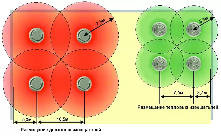
– in the case of flat floors, in the absence of interference and obstacles, smoke and heat detectors protect the area in the form of a circle in the horizontal plane;
– it is necessary to regulate the minimum and maximum distance of detectors from the ceiling.
Fig.1. The simplest scheme smoke and heat detector placement
According to BS 5839-1:2002, the radius of protection for smoke detectors is 7.5 m, for heat detectors - 5.3 m in horizontal projection. Thus, it is easy to determine the placement of detectors in a room of any shape: the distance from any point in the room to the nearest smoke IP in the horizontal projection should be no more than 7.5 m, from the thermal one - no more than 5.3 m. These radii of the protected area determine somewhat larger distances between detectors when arranged in a square grid (Fig. 1) compared to the requirements of NPB 88-2001*. Significant savings in the number of detectors (approximately 1.3 times) are achieved in large rooms when using arranging detectors in a triangular grid (Fig. 2).

Fig.2. Installation of detectors in large rooms
Currently, in practice, these provisions can only be applied when using aspirating detectors. In the Recommendations of the Federal State Institution VNIIPO EMERCOM of Russia on system design fire alarm using aspirating smoke detectors of the LASD and ASD series, it is stated that “when protecting rooms of any shape, the maximum distances between air intake openings and walls are determined based on the fact that the area protected by each air intake opening has the shape of a circle with a radius of 6.36 m (Fig. 3).

Fig.3. Each hole protects a circle with a radius of 6.36 m
Distance to ceiling
According to the British Standard BS5839, smoke detectors must be installed on the ceiling with their sensing elements located below the ceiling within:
1) 25 mm – 600 mm for smoke sensors;
2) 25 mm – 150 mm for thermal sensors.
A layer remains directly next to the ceiling clean air, which determines the minimum distance from the sensitive element of the smoke and heat detector to the ceiling, equal to 25 mm. For the same reason, flush installation of detectors is prohibited. In NPB 88-2001*, such a requirement is indicated so far only for a linear smoke fire detector, clause 12.29. “the optical axis ran at a distance of at least 0.1 m from the ceiling level” and for linear thermal fire detectors, clause 12.37: “the distance from the detector to the ceiling must be at least 15 mm.” According to NPB 88-2001* clause 12.18* for all point fire detectors, “when hanging detectors on a cable, their stable position and orientation in space must be ensured. In this case, the distance from the ceiling to the bottom point of the detector should be no more than 0.3 m.” BS5839 specifies different maximum distances from the floor for a smoke sensor and for a heat sensor. Smoke detectors provide early detection of fire, at the stage of smoldering materials, and can be placed at a distance of about 300 mm from the ceiling, even in the absence of a stratification effect. Unlike smoke detectors, heat detectors do not detect smoldering fires, and at the open fire stage there is a significant increase in temperature; accordingly, there is no stratification effect and an increase in the distance between the ceiling and the heat-sensitive element by more than 150 mm will lead to unacceptably late detection of the fire, i.e. .will make them practically inoperable.
Perforated ceilings
At airports, in large shopping centers etc. Decorative grilles are often used to cover ducts and cables located under the ceiling. For example, “Griiii” type ceilings. How should fire detectors be installed in this case? BS 5839-1:2002 states that sensors mounted on the main ceiling can be used to protect the area below a perforated false ceiling if the following conditions are simultaneously met:
1) the perforation area is more than 40% of any 1m x 1m ceiling section;
2) minimum size each perforation in any section is at least 10 mm;
3) the thickness of the false ceiling is no more than three times the minimum size of each perforation cell.
In all other cases, sensors should be installed below the false ceiling, and if overhead space protection is required, additional sensors should be installed on the main ceiling in the ceiling space.
When the above conditions are met, there is practically no division of the room into two spaces; smoke passes through the perforation of the false ceiling and is detected by detectors installed on the ceiling. These conditions are met with a large margin for the Grilyato type ceiling; for greater persuasiveness, it is recommended to consider it as a decorative lattice that creates virtually no obstacle to the spread of smoke.
Sloping floors
The absence in our standards of the concept of inclined, non-horizontal overlap can lead to serious design errors. The maximum permissible distance from the sensitive element of the detector to the overlap determines the criterion for assessing the horizontality of the overlap, without using any inclination angle values. If the difference in ceiling heights when using smoke detectors does not exceed 600 mm, then smoke accumulates in the upper part of the room and the ceiling is considered horizontal, regardless of the area of the room. Similarly for heat detectors, if the height difference does not exceed 150 mm, the ceiling is also considered horizontal, regardless of the size of the room. With large differences in altitude, smoke with warm air flows up the slope towards the ridge, and the upper part of the volume is filled. In this case, the first row of fire detectors is installed along the ridge, and the remaining rows are installed parallel to the first slopes. It is possible to place detectors at a lower level, while the sensitive elements of the smoke detector should be located no lower than 600 mm from the top of the ceiling, and thermal elements no lower than 150 mm (Fig. 4).

Fig.4. Room protection with slopes at different angles BS 5839-1:2002
In addition, the sloping section of the ceiling, as a rule, increases the rate of rise of the smoke flow and warm air towards the top, thus reducing the delay time before the detector is triggered. Accordingly, BS 5839-1:2002 allows an increase in the distance between detectors in the top row: for each degree of slope angle, the distance between detectors is allowed to increase by 1%, up to a maximum of 25%. If the floor slopes have different angles of inclination, then the distance between the detectors installed along the ridge is selected based on the smaller value determined by the smaller angle of inclination (Fig. 4). In this example, between the detectors along the ridge it is allowed to increase by 18%, i.e. up to 12.39 m. The remaining detectors are installed based on the standard value of the radius of the protected area, equal to 7.5 m in horizontal projection. In this case, it is recommended to pay Special attention when determining the location of the next rows of detectors, in order to avoid gaps between the circles of detectors of different rows and different radii.
Of course, we cannot use these nuances in practice, but the criterion of inclined overlap is quite applicable. According to NPB 88-2001* clause 12.18*, already mentioned above, for all point fire detectors “<...>the distance from the ceiling to the bottom point of the detector should be no more than 0.3 m.” Thus, in a room 9 x 9 m with a height difference of about 0.6 m, it is possible to install the detector in the center of the room, and with a larger height difference it is recommended to place it on a higher part of the ceiling. In this case, the requirement specified in clause 12.18* must be met: “When installing point fire detectors under the ceiling, they should be placed at a distance from the walls of at least 0.1 m.” Note that in BS 5839-1:2002 this distance for horizontal slabs is 0.5 m.
Similar to the requirements for point smoke detectors, the installation of linear smoke detectors in BS 5839-1:2002 requires a beam to horizontal distance of between 25mm and 600mm. In a room with a non-horizontal ceiling, i.e. when the difference in ceiling heights is more than 600 mm, it is necessary to protect the space along the roof ridge. In this case, according to BS 5839-1:2002, the distance between the optical axes linear detectors can also be increased by 1% for each degree of inclination up to a maximum of 25% (Figure 5).

Fig.5. Protecting a room with a sloping ceiling
In our practice, the distance between the optical axes not only cannot be reduced, but also can hardly be measured in a horizontal projection, since Table 6 of NPB 88-2001* indicates the maximum distances directly between the optical axes of detectors without taking into account their possible placement on an inclined overlap

Fig.6. Average room protection
Where linear smoke detectors cannot be installed below the ceiling, for example in atriums with glass domed roofs, BS 5839-1:2002 allows them to be located below 600mm from the ceiling. However, with such placement of detectors, the protected area is significantly reduced and amounts to up to 12.5% of the installation height in each direction from the optical axis (Fig. 6.) Smoke diverges over a larger area with increasing height, therefore, it is more economical to install linear optical detectors at the maximum possible height. So, for example, when installed at a height of 4 m, for reliable detection of a source, the distance between the optical axes should be no more than 1 m, when installed at a height of 20 m, respectively, no more than 5 m.
Floors with beams
In large production premises Usually there are beams of considerable height on the floor. In this case, the placement of detectors must be carried out in accordance with clause 12.20. NPB 88-2001*: “Point smoke and heat fire detectors should be installed in each ceiling compartment with a width of 0.75 m or more, limited by building structures (beams, purlins, slab ribs, etc.) protruding from the ceiling at a distance of more than 0.4 m. If building structures protrude from the ceiling at a distance of more than 0.4 m, and the width of the compartments they form is less than 0.75 m, the area controlled by fire detectors, indicated in tables 5, 8, is reduced by 40%. If there are protruding parts on the ceiling from 0.08 to 0.4 m, the area controlled by fire detectors, indicated in tables 5, 8, is reduced by 25%.”
However, it is not indicated along which axes the distance between the detectors should be reduced. The beams prevent the spread of smoke in the transverse direction, and, therefore, it is necessary to reduce distances in this direction, ensuring a given reduction in the controlled area. It makes no sense to reduce the distances between detectors along the beams, since smoke spreads even faster between the beams, since the effect of limiting the space appears, as in a corridor, where the distances between detectors can be increased by 1.5 times.

Fig.7. Ceiling with beams, M - distance between detectors
BS 5839-1:2002 discusses two options in more detail: linear beams (Figure 7) and honeycombs (Figure 8).

Fig.8. Honeycomb ceiling
The requirements of BS 5839-1:2002 for permissible distances between detectors across beams depending on ceiling height and beam height are given in Table 1.
Table 1
For a honeycomb-shaped ceiling, depending on the ratio of the height of the beam and the width of the cell, fire detectors are installed either on the ceiling or on the beam (Table 2). Here the limit for the height of the beam is 600 mm (as opposed to our 400 mm), but the relative height of the beam is also taken into account - an additional limit, 10% of the height of the room.
table 2
| Ceiling height H (rounded to the nearest integer), m | Beam height D | Maximum distance to the nearest smoke (heat) detector | Detector placement at W | Detector placement at W>4D |
| 6m or less | Less than 10% H | Like a flat ceiling | On the bottom plane of the beams | On the ceiling |
| More than 6 m | Less than 10% H and 600mm or less | Like a flat ceiling | On the bottom plane of the beams | On the ceiling |
| More than 6 m | Less than 10% H and more than 600 mm | Like a flat ceiling | On the bottom plane of the beams | On the ceiling |
| 3m or less | More than 10% H | 4.5 m (3 m) | On the bottom plane of the beams | On the ceiling |
| 4 m | More than 10% H | 5.5 m (4 m) | On the bottom plane of the beams | On the ceiling |
| 5 m | More than 10% H | 6 m (4.5 m) | On the bottom plane of the beams | On the ceiling |
| >= 6 m | More than 10% H | 6.6 m (5 m) | On the bottom plane of the beams | On the ceiling |
Where, H – ceiling height; W – cell width; D – beam height.
The design of the suspended ceiling allows you to hide exhaust ducts, wiring, electrical cables and other communications in the interceiling space, however, this increases the risk of fire. In this connection, the ceiling must be equipped with an automatic fire alarm system.
When is it necessary to install sensors?
Safety standards are constantly changing, so homeowners with suspended ceilings need to regularly monitor new regulations. Thus, some owners are confident that it is the ceiling height that is the fundamental factor in the need to install an alarm. However, this belief is incorrect - fire protection requirements do not depend on the height of the ceiling space, but solely on the presence and amount of flammable cable load. Legally, this is regulated by the following regulations:
- set of rules 13130 of 2009 with mandatory Appendix “A”;
- table “A2”, paragraph 11 and note to paragraph 11 (standard “Fire protection”).
How to determine the need for installation:
Step 1. Look behind the ceiling, find a cable that provides power, outlet wires or a power network.
Step 2. Choose the largest possible area, more than a meter in one direction. Count the number of cables, taking into account their brands, write down the data.
Step 3. For each type of wire, determine the combustible mass indicators according to any directory of cable manufacturers, for example, the Kolchuginsky plant.
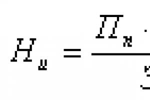
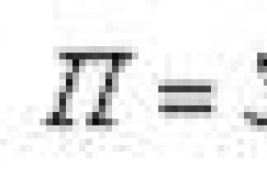
Step 4. Carry out calculations using the formula: A×B=C, where A is the number of wiring of a certain model and brand, B is the flammable mass, and C is the desired flammability parameter. The calculation is performed separately for each cable type, then all results are summed up.

Step 5. Compare the resulting indicator with legal standards:
- up to 1.5 liters per meter – no need to install sensors on the ceiling;
- from 1.5 to 1.7 l – fire safety is ensured in the form of an independent ceiling alarm loop;
- 1.7 l and more - must be installed automatic system fire extinguishing For ceiling heights less than 0.4 meters, a cable is installed.
In this case, the distances between the base floor and suspended ceiling should be sufficient to accommodate the sensors. It is also important to identify the area with the most dense arrangement of wires and other communications - the cables should be at a distance of at least 30 cm from each other.
In what cases is a fire alarm not required?
The need to install an alarm is always determined solely by the combustible load indicator. However, the regulatory safety documentation also establishes a number of other factors under which installation of a fire alarm on a suspended or suspended ceiling is not required:
- If there are wires hidden in insulated corrugated tubes or special steel boxes.
- In the case of installation based on a single-core cable and an NG type electrical supply (non-flammable).
- If there is a single strand of wiring in the suspended ceiling.

Types of fire detectors
Existing sensors have a fairly extensive classification system in accordance with the nuances of the structure of the device and the methods of its functioning. Each of the detectors has its own installation and operation features. So, depending on the type of transmitted signal, sensors are divided into the following categories:
- Single-mode detectors. They signal danger when exposed to an external factor, such as temperature. Currently they are not used in everyday life.
- Dual-mode with “Fire” and “No fire” alarms. At the same time, the absence of a fire signal confirms that the device is in working order and is operating normally.
- Multi-mode with built-in notification programs about device failures.
In addition, detectors are conventionally divided into types according to their location:
- Spot-type household appliances have a single sensor, often built into the housing.
- Multipoint devices are equipped with multiple detectors.
- Linear sirens analyze the space along an arbitrary trajectory. They can be single or paired, autonomous or targeted.

Regardless of the classification, all fire detectors are divided into wired and wireless and differ in the type of detector itself - it is this division that is fundamental when choosing a warning system.
Heat detectors
Heat sensors were the first fire prevention devices. They appeared in everyday life at the beginning of the 19th century, and at that time they looked like two spring-loaded cables with a wax insert in the middle. As the temperature increased, the wax began to melt and the wires shorted, causing an audible alarm. New generation thermal sensors also have melting elements and often use an electrical effect based on the thermocouple principle.

Despite all the advantages of the device, including its low cost, such detectors have one serious drawback - they sound an alarm after the air temperature has risen and a fire has started. It is for this reason that with the development of technology, this type of device gradually lost its relevance.
Smoke detectors
Systems equipped with smoke detectors are by far the most popular fire protection devices for use in homes and work areas. Smoke is the first and main sign of a possible fire, which may appear before an open flame occurs. For example, a faulty electrical wiring is often accompanied by a long process of smoldering with a characteristic caustic fumes. Therefore, this type of sensor helps to identify the source of fire at its initial stage.

The smoke sensor operates on the principle of detecting changes in the transparency of smoky air. In this case, the device is classified depending on the methods of its operation into linear detectors (working with a directed beam in the optical or ultraviolet range) or point detectors (based on infrared radiation). Point detectors are usually simpler than linear ones, but less reliable - thick, dark smoke does not reflect infrared rays, so during such a fire the sensor may not respond.
Flame detectors
This type of siren is usually used to ensure fire safety at production sites. In such rooms, the use of smoke or heat sensors will be difficult due to the constant dustiness of the air or its elevated temperature.

Types of detectors:
- Infrared. Captures the radiant heat of an open flame. If there are regularly operating sources of air heating, groundless alarm activation is excluded.
- Ultraviolet. They are used if there are sources of infrared radiation in the room, for example, an electric heater.
- Sensors that react to the electromagnetic component of the energy released from an open fire.
- Security ultrasonic devices. Interact with fluctuations in air masses. The operating principle is based on the fact that hot air actively rises upward.
Rules for installation and placement of fire sensors on the ceiling
Accommodation security and fire alarm system(OPS or APS) is regulated by the normative act SP 5.13130.2009 as amended on 06/01/2011. In accordance with this document, installation of devices is carried out exclusively on load-bearing elements(stiffeners) or cables. It is important to take into account that it is strictly prohibited to attach sounders to suspended ceiling slabs - this design has poor mechanical stability and low fire resistance.

Sometimes ceiling sensors are also used to ensure indoor security. This is possible in cases where false ceilings have large perforations. According to safety rules, installation of fire detectors behind a suspended ceiling is possible in the following cases:
- in the presence of perforation with an area of 40% of the entire surface with a periodically repeating large pattern;
- with a diameter of one perforation hole of at least 1 cm;
- in case the element size suspended structure does not exceed the minimum size of one cell (for example, Armstrong-type ceilings).
If these requirements are not met, fire detectors must be installed on the walls of the room or directly on the surface of the suspended ceiling. In addition, it is necessary to take into account the sensitivity radius of the devices.
- Installation is carried out according to the “triangular grid” arrangement principle - this will save space and protect the entire surface.
- When calculating the range of the device, the orientation of the sensitivity zone in the horizontal plane is used. For smoke sensors - 7.5 m, for heat sensors - 5.3 m.
- The detector, mounted on the base of a suspended structure, must be positioned so that the sensitive element is below the ceiling level. For smoke - 2.5-60 cm, thermal - 2.5-15 cm.
- The distance from the walls must be at least 0.5 m.
Calculation of the required number of detectors
Before installing smoke sensors, it is necessary to correctly calculate their exact number for a specific room. In this case, it is necessary to take into account the type of devices and the intended connection diagram. It is important to understand that each state's laws will have different installation standards.
IN Russian Federation It is mandatory to install at least 2 sensors per room. The regulations state that detectors are recommended to be installed on each section of the ceiling with a width of 0.75 m or more, as well as on elements building structures with a projection of 0.4 m.
Thus, a separate zone of the inter-ceiling space should be equipped with:
- three sensors, if they are connected to a two-threshold response loop or to three separate loops with a single response threshold;
- four detectors when connected in pairs to two different device loops with the same threshold;
- two devices with an alternating operation circuit.
Despite the fact that point sensors are capable of monitoring up to 25 meters of a room, it is imperative to install at least two of them if they are addressable and at least three if they are analog. This is explained by the fact that the spread of smoke and fire in the ceiling area has its own characteristics, which means that this area is more difficult to control.
Installation procedure
When installing a device, the first thing to determine is required amount sensors and mounting locations, only then does the installation process begin.
In the suspended ceiling
Sensors are most often installed in suspended plasterboard ceilings using the insertion method - the most aesthetic and convenient way. It is recommended to use heat-resistant cables with NG type braid, copper conductors and a minimum cross-section of 0.5 mm. Please note that installing sensors in blind corners between the wall and ceiling is strictly prohibited.
Fire sensor installation diagram:
Step 1. Determining the number of detectors, their approximate location and distance from each other. It should be noted that smoke sensors must be installed both in the suspended structure itself and on it.
Step 2. Fixing sounders is only permissible on a frame or concrete floor in an overhead way. It is possible to insert into a suspended ceiling and fasten it using special mounting rings, but in this case the sensor is additionally fixed to the ceiling with a cable.

Step 3. The device is connected only in the absence of power and in accordance with the diagram indicated on the sensor packaging. Finally, you should check the accuracy of the connection and the performance of the entire system several more times.
In a suspended ceiling
Regulatory documents do not indicate the mandatory location of fire sensors in suspended ceilings; however, the minimum distance from the walls must be maintained. When installing the device, preference should be given to those areas where there will be the greatest coverage of room control, taking into account the range of the sensor.
Installation instructions:
Step 1. Prepare the embedded structure for suspended ceiling. To do this, flexible metal hangers are screwed to a flat plate of plastic or plywood, with the help of which the platform is attached to the concrete floor.
Step 2. Align the mortgage to the level with the future ceiling. Bring the wiring down.

Step 3. Stretch the fabric. At the location of the platform, glue a thermal ring so that the PVC film does not tear, then cut a hole to install the sensor.

Step 4. Connect the device and check its functionality. Screw the sensor to the platform.
Safety precautions and possible installation problems
Even though the system fire alarm must be installed by a qualified organization in compliance with all requirements and standards; sometimes apartment owners try to install the device themselves. Self-installation fire detectors is possible, but certain safety rules must be observed:
- During installation work, it is allowed to use only special stepladders or ladders - any improvised means are strictly prohibited.
- For installation and maintenance Fire safety systems are allowed to be installed by specialists with knowledge of the instructions and specifics of the work.
- Tools used in the process must have insulated handles.
- First, you need to measure the voltage between phases using a portable voltmeter.
- Before installing the system elements, be sure to check the strength of the fire detectors on the suspended ceiling or tension structure.
Common problems during installation and operation
Problem #1: malfunction of one detector while all others are working properly.
Remedy: check the installed smoke sensors and, if necessary, remove them. It should be taken into account that if the voltage indicators are different, then the wiring for fire extinguishing and alarm systems should be located in separate boxes. When laid open, the distance between cables and other communication systems should not be less than 0.5 m.
Problem #2: No alarm.
Remedy: check the mounting surface, turn the optical indicator of the device towards the main entrance.
Problem #3: Battery failure.
Remedy: if the sensor is installed on the ceiling itself, then changing the power system will be quite easy - you just need to carefully unscrew the device from its platform. When installing the device inside a suspended ceiling, you will need to partially dismantle the ceiling panel.
Thus, the main requirement for installing a fire detector remains its effective subsequent operation. When choosing a device, it is advisable to give preference to reliable manufacturers whose models are guaranteed to last for several years.
It is better for the owner of the premises to rely on qualified specialists who can calculate the number of detectors and create correct scheme their location - only with proper installation is it possible to operate fire detectors without failures or malfunctions.
font size
CODE OF RULES FIRE PROTECTION SYSTEMS - FIRE ALARM INSTALLATIONS AND FIRE FIGHTING AUTOMATIC - STANDARDS AND RULES... Relevant in 2018
13.3. Placement of fire detectors
13.3.1. The number of automatic fire detectors is determined by the need to detect fires in a controlled area of premises or areas of premises, and the number of flame detectors is determined by the controlled area of equipment.
13.3.2. In each protected room, at least two fire detectors should be installed, connected according to the logical “OR” circuit.
Note - In the case of using an aspiration detector, unless specifically specified, it is necessary to proceed from the following position: one air intake opening should be considered as one point (addressless) fire detector. In this case, the detector must generate a malfunction signal if the air flow rate in the air intake pipe deviates by 20% from its initial value set as an operating parameter.
13.3.3. In the protected room or designated parts of the room, it is allowed to install one automatic fire detector if the following conditions are simultaneously met:
a) the area of the room is no more than the area protected by the fire detector specified in the technical documentation for it, and no more than the average area indicated in tables 13.3 - 13.6;
b) automatic monitoring of the fire detector’s performance under the influence of environmental factors is provided, confirming the performance of its functions, and a notification of serviceability (malfunction) is generated on the control panel;
c) identification of a faulty detector is ensured using a light indication and the possibility of its replacement by duty personnel within a specified time, determined in accordance with Appendix O;
d) when a fire detector is triggered, a signal is not generated to control fire extinguishing installations or type 5 fire warning systems, as well as other systems, the false operation of which can lead to unacceptable material losses or a decrease in the level of human safety.
13.3.4. Point fire detectors should be installed under the ceiling.
If it is not possible to install detectors directly on the ceiling, they can be installed on cables, as well as on walls, columns and other load-bearing building structures.
When installing point detectors on walls they should be placed at a distance of at least 0.5 m from the corner and at a distance from the ceiling in accordance with Appendix P.
The distance from the top point of the ceiling to the detector at the place of its installation and depending on the height of the room and the shape of the ceiling can be determined in accordance with Appendix P or at other heights, if the detection time is sufficient to perform fire protection tasks in accordance with GOST 12.1.004, which must be confirmed by calculation.
When hanging detectors on a cable, their stable position and orientation in space must be ensured.
In the case of using aspiration detectors, it is allowed to install air intake pipes both horizontally and vertically. vertical plane.
When fire detectors are located at a height of more than 6 m, an access option to the detectors for maintenance and repair must be determined.
13.3.5. In rooms with steep roofs, for example, diagonal, gable, hipped, hipped, saw-toothed, with a slope of more than 10 degrees, some detectors are installed in the vertical plane of the roof ridge or the highest part of the building.
The area protected by one detector installed in the upper parts of roofs increases by 20%.
Note - If the floor plane has different slopes, then the detectors are installed on surfaces with lower slopes.
13.3.6. The placement of point heat and smoke fire detectors should be made taking into account the air flows in the protected room caused by supply or exhaust ventilation, and the distance from the detector to the ventilation hole must be at least 1 m. In the case of using an aspirating fire detector, the distance from the air intake pipe with holes to the ventilation hole is regulated by the permissible air flow for a given type of detector.
13.3.7. The distances between detectors, as well as between the wall and detectors, given in tables 13.3 and 13.5, can be changed within the area given in tables 13.3 and 13.5.
13.3.8. If there are linear beams on the ceiling (Figure 1 - here and below the figures are not given), the distances between point smoke and heat detectors across the beams M are determined according to Table 13.1. The distance of the outermost detector from the wall should not exceed half M. The distance between detectors L is determined according to tables 13.3 and 13.5, respectively, taking into account clause 13.3.10.
Table 13.1
| Ceiling height H (rounded to the nearest whole number), m | Beam height D | Maximum distance to the nearest smoke (heat) detector | Detector placement with cell width W<= 4D | Detector placement for W > 4D |
| 1 | 2 | 3 | 4 | 5 |
| 6m or less | Less than 10% H | Like a flat ceiling | On the bottom plane of the beams | On the ceiling |
| More than 6 m | Less than 10% N and 600mm or less | Like a flat ceiling | On the bottom plane of the beams | On the ceiling |
| More than 6 m | Less than 10% N and more than 600 mm | Like a flat ceiling | On the bottom plane of the beams | On the ceiling |
| 3m or less | More than 10% N | 4.5 m (3 m) | On the bottom plane of the beams | On the ceiling |
| 4 m | More than 10% N | 5.5 m (4 m) | On the bottom plane of the beams | On the ceiling |
| 5 m | More than 10% N | 6 m (4.5 m) | On the bottom plane of the beams | On the ceiling |
| >= 6 m | More than 10% N | 6.6 m (5 m) | On the bottom plane of the beams | On the ceiling |
13.3.12. Fire detectors should be installed in accordance with the requirements of technical documentation for specific types of detectors.
13.3.13. In places where there is danger mechanical damage detector, a protective structure must be provided that does not interfere with its functionality and fire detection efficiency.
13.3.14. If different types of fire detectors are installed in one control zone, their placement is carried out in accordance with the requirements of these standards for each type of detector.
13.3.15. If the predominant fire factor is not determined, it is allowed to install combined fire detectors (smoke - heat) or a combination of smoke and heat fire detectors. In this case, the placement of detectors is carried out according to table 13.5.
If the predominant fire factor is smoke, the detectors are placed according to Table 13.3 or 13.6.
In this case, when determining the number of detectors, a combined detector is taken into account as one detector.
13.3.16. Ceiling-mounted detectors can be used to protect the space below a perforated false ceiling if the following conditions are simultaneously met:
perforation has a periodic structure and its area exceeds 40% of the surface;
the minimum size of each perforation in any section is not less than 10 mm;
the thickness of the false ceiling is no more than three times the minimum size of the perforation cell.
If at least one of these requirements is not met, detectors must be installed on the false ceiling in the main room, and if it is necessary to protect the space behind the suspended ceiling, additional detectors must be installed on the main ceiling.
13.3.17. Detectors should be oriented so that the indicators are directed, if possible, towards the door leading to the exit from the room.
13.3.18. The placement and use of fire detectors, the procedure for use of which is not defined in this set of rules, must be carried out in accordance with the recommendations agreed upon in the prescribed manner.
Manual fire detector- this, according to the defining requirement for technical means APS, a technical product for manually sending an alarm signal. Short name/abbreviation – IPR.
Such products duplicating automatic transmission signals from other devices similar in purpose, such as gas or gas, are part of almost all APS installations/systems.
In addition, they can be used as remote start devices for stations/pumps of internal fire water supply systems, buildings/structures - duplicating elements of automatic and local installations manual method actuation; switching on / pressurizing air, for unlocking electromechanical / magnetic locks of emergency exit doors, as well as panic buttons as part of a security alarm.
Nevertheless, the main purpose of the IPR is to generate the “Fire” signal manually by eyewitnesses who have discovered signs of fire in the premises of buildings/structures, on the territory of the enterprise where they are located; regardless of who they are - employees, engineering service personnel on duty, security officers or visitors.
Kinds
There are two types of IPR as part of APS systems:
- Threshold. Traditional fire detectors in the premises of a building/territory, transmitting an alarm signal when closed/opened electrical circuit device included in the PS loop. A significant disadvantage is the lack of an exact address of the source of the fire, depending on how many buildings/structures on the territory or rooms in the building/structures are protected by this PS loop.
As a rule, it is simply impossible to obtain clearer information about the location of a fire than the floor of a building or a building/group of buildings on standard models of APS devices using threshold IPRs, because use a separate PS cable for each manual call point unreasonably expensive.
- Address. The great fundamental advantage of such IPR is the transmission of the exact coordinates of the fire in buildings, on the territory of the protected object. As a rule, they are used in addressable or addressable-analog alarm systems that use a PC with the appropriate software installed as a remote control for a security/fire monitoring/control station. The latest developments, modern models such products, produced by both foreign and domestic manufacturers, are IPRs capable of transmitting an alarm message via radio or using cellular communication both GSM and other standards.
It is worth taking a closer look at the main types of products called IPR to understand their operating principle:
- Manual addressable fire detector. According to , which establishes standards for the design of APS/AUPT installations, this is an IPR that simultaneously transmits, along with an alarm message about a fire, the address code of its exact location/installation as part of the fire protection automatics of the protected object to the receiving and control device (RCD).
The accuracy of targeted IPRs - before the location of a building/structure or indicating a specific place on the territory of an enterprise/organization allows you to quickly monitor a fire signal and take the necessary measures without wasting precious time in such a situation; which is much more difficult in all respects when using traditional threshold IPRs included in long-distance PS loops that protect many rooms in a public, administrative building or buildings on the territory of an industrial enterprise.
This is very convenient, clearly visible on the PC monitor when using an automated workstation, for example, with the package software system security complex "Orion" from the leader Russian manufacturers equipment - NVP "Bolid" from the town of Korolev near Moscow.
The use of targeted IPR in such centralized integrated control systems, including the use of video surveillance cameras, for obvious reasons, reduces/prevents both the number of false/accidental alarms and the possibility of deliberately pressing such detectors, including for hooligan reasons. At the same time, hundreds of detectors, including IPRs of this type, can be included in one loop of an addressable analogue or addressable receiving control device APS.
- Manual radio fire detector is a modern wireless device. Most often used as part of targeted integrated security systems that protect objects - complexes of buildings of large area/storeys or industrial and warehouse facilities located over a large area where the use of wired systems is difficult, impractical or unprofitable for various reasons. A stable, reliable alarm signal is transmitted over a dedicated radio channel over a long distance. For example, up to 600 m in open space for IPR 51310-1, which is also marked IPR-R, manufactured by the Argus-Spectrum company from St. Petersburg.
- Fire detector manual electric contact– this is the oldest product in design, whose history of use goes back more than a century; but a reliable, simple and, importantly, inexpensive fire notification device. Despite the emergence of more technically “advanced” addressable, radio-channel IPRs, including those using the GSM communication standard; mass production of electric contact detectors, the principle of operation and design of which are indicated in the name itself, is not reduced even today. They are in demand for equipping building premises and enterprise premises in all typical cases when the requirements for their installation and location accuracy are not so high.
Although all other IPRs can be classified in this general form - based on the principle of closing/opening an electrical circuit - traditionally, they include “older” product models. Addressable, radio-channel manual call points received their own name due to a fundamentally different way of exchanging information with compatible APS devices.
Various types/types of IPR can also include standard product models for installation indoors, in areas where they will be used under normal conditions; and manual call points in explosion-proof housings, installed in premises of categories A and B.
Specifications
These parameters include:
- Simplicity and ease of use of IPR for its intended purpose. It should be easily distinguishable against the background of the interior decoration of the premises, on the wall of the building, or on a pillar/support when installed on the premises, which is facilitated by the red color of the body; contrasting, usually white color of the detector element that activates it, as well as dimensions - at least 5 thousand mm 2.
- The design must allow it to be triggered almost on the run, when the person who discovered the fire is in a stressful/extreme situation. And, of course, do not require a preliminary study of the technical passport of the product, or a practical study of its structure.
- Housing protection - no less than IP IPR must be resistant to vibration, electromagnetic influence, high air humidity, and changes in ambient temperature over a wide range, so they are installed not only indoors, but also on the territory of enterprises.
All these and many more technical requirements, as well as methods for testing IPR for “professional suitability” are set out in.
It should be noted that most of the requirements are advisory, which allows manufacturers to make full use of their imagination in designing IPRs “different from others,” which is not at all beneficial to the matter. Thus, that part of the device that causes it to operate may be a fragile element that should/may be broken with a light blow, as well as with a lever, button or other device (!). It is simply impossible to talk about the unification of products with such free interpretations of the main element of the IPR.
There are extremely ineffective designs of detectors on sale with levers, push/slide brackets, and strips. Almost puzzles created decades ago, archaic both in appearance and in the way they are used/returned to working order after use.
Therefore, when choosing a product model, it is best to use the opinion of even non-specialists from design organizations, who often, out of habit, include outdated equipment in the specification of working documentation; and the advice of engineering and technical personnel of enterprises/organizations performing, on the basis of a license from the Ministry of Emergency Situations, installation/maintenance of APS/AUPT systems, whose knowledge and experience will suggest the optimal solution for a given protected object.
Installation
When choosing the installation location of the IPR, you should be guided by Appendix N SP 5.13130.2009. Its main instructions are installation along emergency routes, at exits from premises/buildings, in lobbies, corridors, on landings with convenient access to them, and maximum possible lighting.
According to the installation height of the IPR - 1.5 m, and the maximum distance between them in the premises - 50 m, in the territory - 150 m. In the latter case, the devices must be protected from precipitation.
Product model manufacturers
In order to get at least a little orientated in the variety of commercial products produced by many manufacturers of APS equipment, it is worth giving examples of some popular, therefore, proven by installation/operation experience, product models:

- . Produced by Rubezh Group of Companies. Power supply – 3–30 V, current consumption – no more than 50 µA. Dimensions – 88 x 85 x 43 mm, weight – less than 0.15 kg. Housing protection – IP Operating temperature range – from – 40 to + 60℃. An excellent detector whose design, appearance, including labeling, complies with both Russian and foreign compliance/certification standards; which is important in many situations during design and subsequent maintenance.

- . There are quite a few products with this marking from different manufacturers with additional names. For example, IPR 535 “Garant” produced by “Spetspribor”. This detector has housing protection IP 67, resistance to aggressive environments, explosion-proof design. And also IPR 535-7, produced by the Siberian Arsenal company. This is a classic manual call point from the past of these devices with an additional “fool proof” cover and a downward push button (!), as indicated on the product, but in fact – a sliding design. All together leads to unnecessary, unnecessary manipulations with the device; and the one who presses such a “button” will never transmit an alarm signal to anyone.

- . The situation is similar with various manufacturers, designations/names, markings. An example is the above IPR 513-10, as well as the next product in the list.

- produced by NVP "Bolid". This is a modern addressable electrical contact device that meets the highest standards. Up to 127 IPR 513-3A can be connected to one PS loop using the “ ” series control panel produced by the Bolid company, which is impressive.
Conclusions: find IPRs that correspond to the situation and are compatible with the selected PCPs, technical specifications and cost, it is not difficult if you seek the help of specialists.