To perform the calculation of the wall for stability, you first need to understand their classification (see SNiP II -22-81 "Stone and reinforced masonry structures", as well as a guide to SNiP) and understand what types of walls are:
1. load-bearing walls- these are the walls on which floor slabs, roof structures, etc. rest. The thickness of these walls must be at least 250 mm (for brickwork). These are the most responsible walls in the house. They need to count on strength and stability.
2. Self-supporting walls- these are walls on which nothing rests, but they are affected by the load from all the overlying floors. In fact, in a three-story house, for example, such a wall would be three stories high; the load on it only from the own weight of the masonry is significant, but the question of the stability of such a wall is also very important - the higher the wall, the greater the risk of its deformation.
3. Curtain walls- these are external walls that rely on the ceiling (or on other structural elements) and the load on them falls from the height of the floor only from the own weight of the wall. The height of non-bearing walls must be no more than 6 meters, otherwise they become self-supporting.
4. Partitions are internal walls less than 6 meters high, perceiving only the load from its own weight.
Let's deal with the issue of wall stability.
The first question that arises in the "uninitiated" person: well, where can the wall go? Let's find the answer with an analogy. Take a hardcover book and put it on its edge. The larger the format of the book, the less stable it will be; on the other hand, the thicker the book, the better it will stand on its edge. The situation is the same with walls. The stability of the wall depends on the height and thickness.
Now let's take the worst option: a thin large format notebook and put it on edge - it will not only lose stability, but also bend. So the wall, if the conditions for the ratio of thickness and height are not met, will begin to bend out of the plane, and eventually crack and collapse.
What is needed to avoid this phenomenon? It is necessary to study p.p. 6.16...6.20 SNiP II -22-81.


Consider the issues of determining the stability of walls using examples.
Example 1 Given a partition made of aerated concrete grade M25 on a mortar grade M4 3.5 m high, 200 mm thick, 6 m wide, not connected with the ceiling. In the partition there is a doorway 1x2.1 m. It is necessary to determine the stability of the partition.
From table 26 (item 2) we determine the masonry group - III. From tables s 28 we find? = 14. Because the partition is not fixed in the upper section, it is necessary to reduce the value of β by 30% (according to paragraph 6.20), i.e. β = 9.8.
k 1 \u003d 1.8 - for a partition that does not carry a load with a thickness of 10 cm, and k 1 \u003d 1.2 - for a partition 25 cm thick. By interpolation, we find for our partition 20 cm thick k 1 \u003d 1.4;
k 3 \u003d 0.9 - for partitions with openings;
so k \u003d k 1 k 3 \u003d 1.4 * 0.9 \u003d 1.26.
Finally β = 1.26 * 9.8 = 12.3.
Let's find the ratio of the height of the partition to the thickness: H / h = 3.5/0.2 = 17.5 > 12.3 - the condition is not met, a partition of such a thickness with a given geometry cannot be made.
How can this problem be solved? Let's try to increase the grade of the solution to M10, then the masonry group will become II, respectively β = 17, and taking into account the coefficients β = 1.26 * 17 * 70% = 15< 17,5 - этого оказалось недостаточно. Увеличим марку газобетона до М50, тогда группа кладки станет I , соответственно β = 20, а с учетом коэффициентов β = 1,26*20*70% = 17.6 >17.5 - the condition is met. It was also possible, without increasing the grade of aerated concrete, to lay structural reinforcement in the partition in accordance with clause 6.19. Then β increases by 20% and the stability of the wall is ensured.
Example 2 Dana outdoor not bearing wall from lightweight masonry made of bricks of the M50 brand on the mortar of the M25 brand. The height of the wall is 3 m, the thickness is 0.38 m, the length of the wall is 6 m. The wall with two windows is 1.2x1.2 m in size. It is necessary to determine the stability of the wall.
From table 26 (item 7) we determine the masonry group - I. From tables 28 we find β = 22. the wall is not fixed in the upper section, it is necessary to reduce the value of β by 30% (according to paragraph 6.20), i.e. β = 15.4.
We find the coefficients k from tables 29:
k 1 \u003d 1.2 - for a wall that does not carry a load with a thickness of 38 cm;
k 2 = √А n /A b = √1.37 / 2.28 = 0.78 - for a wall with openings, where A b = 0.38 * 6 = 2.28 m 2 - the area of the horizontal section of the wall, taking into account windows, And n \u003d 0.38 * (6-1.2 * 2) \u003d 1.37 m 2;
so k \u003d k 1 k 2 \u003d 1.2 * 0.78 \u003d 0.94.
Finally β = 0.94 * 15.4 = 14.5.
Let's find the ratio of the height of the partition to the thickness: H / h \u003d 3 / 0.38 \u003d 7.89< 14,5 - условие выполняется.
It is also necessary to check the condition stated in paragraph 6.19:
H + L = 3 + 6 = 9 m< 3kβh = 3*0,94*14,5*0,38 = 15.5 м - условие выполняется, устойчивость стены обеспечена.
Attention! For the convenience of answering your questions, a new section "FREE CONSULTATION" has been created.
class="eliadunit">
Comments
« 3 4 5 6 7 8
0 #212 Alexey 21.02.2018 07:08
Quoting Irina:
reinforcement profiles will not replace
Quoting Irina:
about the foundation: voids are allowed in the body of concrete, but not from below, so as not to reduce the area of \u200b\u200bsupport, which is responsible for the bearing capacity. That is, there should be a thin layer of reinforced concrete underneath.
And what kind of foundation - tape or slab? What soils?
The soils are not yet known, most likely there will be a clear field of all sorts of loam, I originally thought the slab, but it will come out a little low, I want it higher, and I also have to remove the upper fertile layer, so I tend to ribbed or even box foundation. I don’t need a lot of soil bearing capacity - the house was still decided on the 1st floor, and expanded clay concrete is not very heavy, freezing there is no more than 20 cm (although according to the old Soviet standards 80).
I think to remove upper layer 20-30 cm, lay out geotextiles, cover with river sand and level with compaction. Then a light preparatory screed - for leveling (it seems that they don’t even make reinforcement into it, although I’m not sure), on top of the waterproofing with a primer
and then there’s already a dilemma - even if you tie the reinforcement frames 150-200mm wide x 400-600mm high and lay them in meter steps, then you still need to form voids between these frames and ideally these voids should be on top of the reinforcement (yes also with some distance from the preparation, but at the same time, they will also need to be reinforced from above with a thin layer under a 60-100mm screed) - I think the PPS plates should be monolithic as voids - theoretically it will be possible to fill this in 1 run with vibration.
Those. as if in appearance a slab 400-600mm with powerful reinforcement every 1000-1200mm the volumetric structure is uniform and light in other places, while inside about 50-70% of the volume there will be foam (in unloaded places) - i.e. in terms of the consumption of concrete and reinforcement - it is quite comparable with a 200mm slab, but + a bunch of relatively cheap foam and more work.
If somehow we could replace the foam plastic with simple soil / sand, it would be even better, but then instead of easy preparation, it would be wiser to do something more serious with reinforcement and removal of reinforcement into beams - in general, I lack both theory and practical experience.
0 #214 Irina 22.02.2018 16:21
Quote:
why fight it? you just need to take into account in the calculation and design. You see, expanded clay concrete is good enough wall material with its own list of advantages and disadvantages. Just like any other material. Now if you want to use it for monolithic floor, I would dissuade you, becausesorry, in general they just write that in lightweight concrete (expanded concrete) there is a poor connection with reinforcement - how to deal with this? as I understand it, the stronger the concrete and the larger the surface area of the reinforcement, the better the connection will be, i.e. you need expanded clay concrete with the addition of sand (and not just expanded clay and cement) and thin reinforcement, but more often
Quote:
Exterior load-bearing walls should, at a minimum, be designed for strength, stability, local collapse and resistance to heat transfer. To find out how thick should it be Brick wall , you need to calculate it. In this article we will consider the calculation of the bearing capacity of brickwork, and in the following articles - the rest of the calculations. In order not to miss the release of a new article, subscribe to the newsletter and you will find out what the thickness of the wall should be after all the calculations. Since our company is engaged in the construction of cottages, that is, low-rise construction, we will consider all calculations for this category.
carriers walls are called that perceive the load from floor slabs, coatings, beams, etc. resting on them.
You should also take into account the brand of brick for frost resistance. Since everyone builds a house for himself, at least for a hundred years, then with a dry and normal humidity regime of the premises, a grade (M rz) of 25 and above is accepted.
When building a house, cottage, garage, outbuildings and other structures with dry and normal humidity conditions, it is recommended to use hollow bricks for external walls, since its thermal conductivity is lower than that of solid bricks. Accordingly, in the heat engineering calculation, the thickness of the insulation will turn out to be less, which will save cash when buying it. Solid brick for external walls should be used only if it is necessary to ensure the strength of the masonry.
Reinforcement of masonry allowed only in the case when the increase in the grade of brick and mortar does not allow to provide the required bearing capacity.
An example of the calculation of a brick wall.
The bearing capacity of brickwork depends on many factors - on the brand of brick, brand of mortar, on the presence of openings and their sizes, on the flexibility of the walls, etc. The calculation of the bearing capacity begins with the definition of the design scheme. When calculating walls for vertical loads, the wall is considered to be supported by hinged-fixed supports. When calculating walls for horizontal loads (wind), the wall is considered to be rigidly clamped. It is important not to confuse these diagrams, since the moment diagrams will be different.
Choice of design section.
In blank walls, the section I-I at the level of the bottom of the floor with the longitudinal force N and the maximum bending moment M is taken as the calculated one. It is often dangerous section II-II, since the bending moment is slightly less than the maximum and is equal to 2/3M, and the coefficients m g and φ are minimal.
In walls with openings, the section is taken at the level of the bottom of the lintels.
Let's look at the section I-I.
From a previous article Collection of loads on the wall of the first floor we take the obtained value of the total load, which includes the loads from the floor of the first floor P 1 \u003d 1.8t and the overlying floors G \u003d G P + P 2 +G 2 = 3.7t:
N \u003d G + P 1 \u003d 3.7t + 1.8t \u003d 5.5t
The floor slab rests on the wall at a distance a=150mm. The longitudinal force P 1 from the overlap will be at a distance a / 3 = 150 / 3 = 50 mm. Why 1/3? Because the stress diagram under the support section will be in the form of a triangle, and the center of gravity of the triangle is just 1/3 of the support length.
The load from the overlying floors G is considered to be applied in the center.
Since the load from the floor slab (P 1) is not applied in the center of the section, but at a distance from it equal to:
e = h / 2 - a / 3 = 250mm / 2 - 150mm / 3 = 75 mm = 7.5 cm,
then it will create a bending moment (M) in section I-I. Moment is the product of force on the shoulder.
M = P 1 * e = 1.8t * 7.5cm = 13.5t * cm
Then the eccentricity of the longitudinal force N will be:
e 0 \u003d M / N \u003d 13.5 / 5.5 \u003d 2.5 cm
Since the load-bearing wall is 25cm thick, the calculation should take into account the random eccentricity e ν = 2cm, then the total eccentricity is:
e 0 \u003d 2.5 + 2 \u003d 4.5 cm
y=h/2=12.5cm
When e 0 \u003d 4.5 cm< 0,7y=8,75 расчет по раскрытию трещин в швах кладки можно не производить.
The strength of the masonry of an eccentrically compressed element is determined by the formula:
N ≤ m g φ 1 R A c ω
Odds m g And φ 1 in the section under consideration, I-I are equal to 1.
Brick - strong enough construction material, especially full-bodied, and when building houses of 2-3 floors, walls made of ordinary ceramic bricks, as a rule, do not need additional calculations. However, situations are different, for example, it is planned two-storey house with a terrace on the second floor. Metal crossbars, on which they will also rely metal beams terrace ceilings, it is planned to lean on brick columns made of face hollow brick 3 meters high, there will be more columns 3 meters high, on which the roof will rest:
In this case, a natural question arises: what is the minimum section of the columns that will provide the required strength and stability? Of course, the idea of laying clay brick columns, and even more so the walls of the house, is far from new, and all possible aspects of the calculations of brick walls, walls, pillars, which are the essence of the column, are set out in sufficient detail in SNiP II-22-81 (1995) "Stone and reinforced masonry structures". It is this normative document that should be followed in the calculations. The calculation below is nothing more than an example of using the specified SNiP.
To determine the strength and stability of the columns, you need to have a lot of initial data, such as: the brand of brick for strength, the area of support of the crossbars on the columns, the load on the columns, the sectional area of the column, and if none of this is known at the design stage, then you can do in the following way:
with central compression
Designed: Terrace with dimensions of 5x8 m. Three columns (one in the middle and two along the edges) made of facing hollow brick with a section of 0.25x0.25 m. The distance between the axes of the columns is 4 m. The brick strength grade is M75.
With such a design scheme, the maximum load will be on the middle lower column. It is she who should be counted on strength. The load on the column depends on many factors, in particular on the area of construction. For example, snow load for roofing in St. Petersburg is 180 kg/m², and in Rostov-on-Don - 80 kg/m². Taking into account the weight of the roof itself 50-75 kg/m², the load on the column from the roof for Pushkin, Leningrad Region, can be:
N from the roof = (180 1.25 +75) 5 8/4 = 3000 kg or 3 tons
Since the actual loads from the floor material and from people sitting on the terrace, furniture, etc. are not yet known, but reinforced concrete slab not exactly planned, but it is assumed that the floor will be wooden, from separately lying edged boards, then to calculate the load from the terrace, you can take a uniformly distributed load of 600 kg/m², then the concentrated force from the terrace acting on the central column will be:
N from the terrace = 600 5 8/4 = 6000 kg or 6 tons
The own weight of columns 3 m long will be:
N from the column \u003d 1500 3 0.38 0.38 \u003d 649.8 kg or 0.65 tons
Thus, the total load on the middle lower column in the section of the column near the foundation will be:
N with about \u003d 3000 + 6000 + 2 650 \u003d 10300 kg or 10.3 tons
However, in this case, it can be taken into account that there is not a very high probability that the temporary load from snow, which is maximum in winter time, and temporary load on the ceiling, maximum in summer, will be applied simultaneously. Those. the sum of these loads can be multiplied by a probability factor of 0.9, then:
N with about \u003d (3000 + 6000) 0.9 + 2 650 \u003d 9400 kg or 9.4 tons
The calculated load on the outer columns will be almost two times less:
N kr \u003d 1500 + 3000 + 1300 \u003d 5800 kg or 5.8 tons
2. Determination of the strength of brickwork.
The brand of brick M75 means that the brick must withstand a load of 75 kgf / cm & sup2, however, the strength of the brick and the strength of the brickwork are two different things. The following table will help you understand this:
Table 1. Calculated compressive strengths for masonry

But that's not all. All the same SNiP II-22-81 (1995) p. 3.11 a) recommends that if the area of pillars and piers is less than 0.3 m2, multiply the value of the design resistance by the coefficient of working conditions γ c \u003d 0.8. And since the cross-sectional area of our column is 0.25x0.25 \u003d 0.0625 m & sup2, we will have to use this recommendation. As you can see, for a brick of the M75 brand, even when using the M100 masonry mortar, the strength of the masonry will not exceed 15 kgf / cm². Eventually design resistance for our column will be 15 0.8 = 12 kg / cm & sup2, then the maximum compressive stress will be:
10300/625 = 16.48 kg/cm² > R = 12 kgf/cm²
Thus, to ensure the necessary strength of the column, it is necessary either to use a brick of greater strength, for example, M150 (the calculated compressive strength with a brand of mortar M100 will be 22 0.8 = 17.6 kg / cm & sup2) or increase the section of the column or use transverse reinforcement of the masonry. For now, let's focus on using a more durable face brick.
3. Determination of the stability of a brick column.
The strength of brickwork and the stability of a brick column are also different things and all the same SNiP II-22-81 (1995) recommends determining the stability of a brick column using the following formula:
N ≤ m g φRF (1.1)
m g- coefficient taking into account the influence of long-term load. In this case, relatively speaking, we are lucky, since at the height of the section h≤ 30 cm, the value of this coefficient can be taken equal to 1.
φ - coefficient of buckling, depending on the flexibility of the column λ . To determine this coefficient, you need to know the estimated length of the column l o, but it does not always coincide with the height of the column. The subtleties of determining the estimated length of the structure are not set out here, we only note that according to SNiP II-22-81 (1995) p. 4.3: "The estimated heights of walls and pillars l o when determining the coefficients of buckling φ depending on the conditions of their support on horizontal supports, one should take:
a) with fixed hinged supports l o = H;
b) with an elastic upper support and rigid pinching in the lower support: for single-span buildings l o = 1.5H, for multi-span buildings l o = 1.25H;
c) for free-standing structures l o = 2H;
d) for structures with partially pinched support sections - taking into account the actual degree of pinching, but not less than l o = 0.8N, Where H- the distance between ceilings or other horizontal supports, with reinforced concrete horizontal supports, the distance between them in the light.
At first glance, our calculation scheme can be considered as satisfying the conditions of paragraph b). i.e. you can take l o = 1.25H = 1.25 3 = 3.75 meters or 375 cm. However, we can confidently use this value only if the lower support is really rigid. If a brick column will be laid out on a roofing material waterproofing layer laid on a foundation, then such a support should rather be considered as hinged, and not rigidly clamped. And in this case, our construction in a plane parallel to the plane of the wall is geometrically variable, since the structure of the ceiling (separately lying boards) does not provide sufficient rigidity in this plane. There are 4 ways out of this situation:
1. Apply a fundamentally different design scheme, for example - metal columns rigidly embedded in the foundation, to which the floor crossbars will be welded, then, for aesthetic reasons, the metal columns can be overlaid with any brand of face brick, since the metal will carry the entire load. In this case, it is true that metal columns need to be calculated, but the estimated length can be taken l o = 1.25H.
2. Make another cover, for example from sheet materials, which will allow us to consider both the upper and lower column supports as hinged, in this case l o=H.
3. Make a hardness diaphragm in a plane parallel to the plane of the wall. For example, along the edges, lay out not columns, but rather piers. This will also allow us to consider both the upper and lower column supports as hinged ones, but in this case it is necessary to additionally calculate the stiffness diaphragm.
4. Ignore the above options and count the columns as free-standing with a rigid bottom support, i.e. l o = 2H. In the end, the ancient Greeks put up their columns (though not of brick) without any knowledge of the resistance of materials, without the use of metal anchors, and there were no such carefully written building codes in those days, nevertheless, some columns stand and to this day.
Now, knowing the estimated length of the column, you can determine the coefficient of flexibility:
λ h =l o /h (1.2) or
λ i =l o (1.3)
h- the height or width of the section of the column, and i- radius of inertia.
In principle, it is not difficult to determine the radius of gyration, you need to divide the moment of inertia of the section by the area of the section, and then extract the square root from the result, but in this case this is not very necessary. Thus λh = 2 300/25 = 24.
Now, knowing the value of the coefficient of flexibility, we can finally determine the coefficient of buckling from the table:
table 2. Buckling coefficients for masonry and reinforced masonry structures
(according to SNiP II-22-81 (1995))

At the same time, the elastic characteristic of the masonry α determined by the table:
Table 3. Elastic characteristic of masonry α (according to SNiP II-22-81 (1995))

As a result, the value of the buckling coefficient will be about 0.6 (with the value of the elastic characteristic α = 1200, according to item 6). Then the maximum load on the central column will be:
N p \u003d m g φγ with RF \u003d 1 0.6 0.8 22 625 \u003d 6600 kg< N с об = 9400 кг
This means that the accepted section of 25x25 cm is not enough to ensure the stability of the lower central centrally compressed column. To increase stability, the most optimal would be to increase the section of the column. For example, if you lay out a column with a void inside of one and a half bricks, with dimensions of 0.38x0.38 m, then in this way not only the cross-sectional area of \u200b\u200bthe column will increase to 0.13 m2 or 1300 cm2, but the radius of gyration of the column will also increase to i= 11.45 cm. Then λi = 600/11.45 = 52.4, and the value of the coefficient φ = 0.8. In this case, the maximum load on the central column will be:
N p = m g φγ with RF = 1 0.8 0.8 22 1300 = 18304 kg > N with about = 9400 kg
This means that a section of 38x38 cm is enough to ensure the stability of the lower central centrally compressed column with a margin, and even the brand of brick can be reduced. For example, with the originally adopted brand M75, the ultimate load will be:
N p \u003d m g φγ with RF \u003d 1 0.8 0.8 12 1300 \u003d 9984 kg\u003e N with about \u003d 9400 kg
It seems to be everything, but it is desirable to take into account one more detail. In this case, it is better to make the foundation tape (single for all three columns), and not columnar (separately for each column), otherwise even small subsidence of the foundation will lead to additional stresses in the body of the column and this can lead to destruction. Taking into account all of the above, the section of columns 0.51x0.51 m will be the most optimal, and from an aesthetic point of view, such a section is optimal. The cross-sectional area of such columns will be 2601 cm².
An example of calculating a brick column for stability
under eccentric compression
The extreme columns in the designed house will not be centrally compressed, since the crossbars will rest on them only on one side. And even if the crossbars are laid on the entire column, then all the same, due to the deflection of the crossbars, the load from the floor and roof will be transferred to the extreme columns not in the center of the column section. Where exactly the resultant of this load will be transferred depends on the angle of inclination of the crossbars on the supports, the elastic moduli of the crossbars and columns, and a number of other factors. This displacement is called the load application eccentricity e o. In this case, we are interested in the most unfavorable combination of factors, in which the floor load on the columns will be transferred as close as possible to the edge of the column. This means that, in addition to the load itself, the bending moment will also act on the columns, equal to M = Ne o, and this moment must be taken into account in the calculations. IN general case The stability test can be performed using the following formula:
N = φRF - MF/W (2.1)
W- section modulus. In this case, the load for the lower extreme columns from the roof can be conditionally considered to be centrally applied, and the eccentricity will be created only by the load from the ceiling. With an eccentricity of 20 cm
N p \u003d φRF - MF / W \u003d1 0.8 0.8 12 2601- 3000 20 2601· 6/51 3 = 19975.68 - 7058.82 = 12916.9 kg >N cr = 5800 kg
Thus, even with a very large load application eccentricity, we have more than a double margin of safety.
Note: SNiP II-22-81 (1995) "Stone and reinforced masonry structures" recommends using a different method for calculating the section, taking into account the features of stone structures, but the result will be approximately the same, therefore the calculation method recommended by SNiP is not given here.
Exterior load-bearing walls should, at a minimum, be designed for strength, stability, local collapse and resistance to heat transfer. To find out how thick should a brick wall be , you need to calculate it. In this article we will consider the calculation of the bearing capacity of brickwork, and in the following articles - the rest of the calculations. In order not to miss the release of a new article, subscribe to the newsletter and you will find out what the thickness of the wall should be after all the calculations. Since our company is engaged in the construction of cottages, that is, low-rise construction, we will consider all calculations for this category.
carriers walls are called that perceive the load from floor slabs, coatings, beams, etc. resting on them.
You should also take into account the brand of brick for frost resistance. Since everyone builds a house for himself, at least for a hundred years, then with a dry and normal humidity regime of the premises, a grade (M rz) of 25 and above is accepted.
When building a house, cottage, garage, outbuildings and other structures with dry and normal humidity conditions, it is recommended to use hollow bricks for external walls, since its thermal conductivity is lower than that of solid bricks. Accordingly, with a thermal engineering calculation, the thickness of the insulation will turn out to be less, which will save money when buying it. Solid brick for external walls should be used only if it is necessary to ensure the strength of the masonry.
Reinforcement of masonry allowed only in the case when the increase in the grade of brick and mortar does not allow to provide the required bearing capacity.
An example of the calculation of a brick wall.
The bearing capacity of brickwork depends on many factors - on the brand of brick, brand of mortar, on the presence of openings and their sizes, on the flexibility of the walls, etc. The calculation of the bearing capacity begins with the definition of the design scheme. When calculating walls for vertical loads, the wall is considered to be supported by hinged-fixed supports. When calculating walls for horizontal loads (wind), the wall is considered to be rigidly clamped. It is important not to confuse these diagrams, since the moment diagrams will be different.
Choice of design section.
In blank walls, the section I-I at the level of the bottom of the floor with the longitudinal force N and the maximum bending moment M is taken as the calculated one. It is often dangerous section II-II, since the bending moment is slightly less than the maximum and is equal to 2/3M, and the coefficients m g and φ are minimal.
In walls with openings, the section is taken at the level of the bottom of the lintels.
Let's look at the section I-I.
From a previous article Collection of loads on the wall of the first floor we take the obtained value of the total load, which includes the loads from the floor of the first floor P 1 \u003d 1.8t and the overlying floors G \u003d G P + P 2 +G 2 = 3.7t:
N \u003d G + P 1 \u003d 3.7t + 1.8t \u003d 5.5t
The floor slab rests on the wall at a distance a=150mm. The longitudinal force P 1 from the overlap will be at a distance a / 3 = 150 / 3 = 50 mm. Why 1/3? Because the stress diagram under the support section will be in the form of a triangle, and the center of gravity of the triangle is just 1/3 of the support length.
The load from the overlying floors G is considered to be applied in the center.
Since the load from the floor slab (P 1) is not applied in the center of the section, but at a distance from it equal to:
e = h / 2 - a / 3 = 250mm / 2 - 150mm / 3 = 75 mm = 7.5 cm,
then it will create a bending moment (M) in section I-I. Moment is the product of force on the shoulder.
M = P 1 * e = 1.8t * 7.5cm = 13.5t * cm
Then the eccentricity of the longitudinal force N will be:
e 0 \u003d M / N \u003d 13.5 / 5.5 \u003d 2.5 cm
Since the load-bearing wall is 25cm thick, the calculation should take into account the random eccentricity e ν = 2cm, then the total eccentricity is:
e 0 \u003d 2.5 + 2 \u003d 4.5 cm
y=h/2=12.5cm
When e 0 \u003d 4.5 cm< 0,7y=8,75 расчет по раскрытию трещин в швах кладки можно не производить.
The strength of the masonry of an eccentrically compressed element is determined by the formula:
N ≤ m g φ 1 R A c ω
Odds m g And φ 1 in the section under consideration, I-I are equal to 1.
|
Load on the pier at the level of the bottom of the crossbar of the floor of the first floor, kN |
Values, kN |
|
snow for II snow region |
1000*6,74*(23,0*0,5+0,51+0,25)*1,4*0,001=115,7 |
|
rolled roofing carpet-100N/m 2 |
100*6,74*(23,0*0,5+0,51+0,25)*1,1*0,001=9,1 |
|
asphalt screed at p=15000N/m 3 15 mm thick |
15000*0,015*6,74*23,0*0,5*1,2*0,001=20,9 |
|
insulation - wood-fiber boards 80 mm thick with a density of p \u003d 3000N / m 3 |
3000*0,08*6,74*23,0*0,5*1,2*0,001=22,3 |
|
Vapor barrier - 50N / m 2 |
50*6,74*23,0*0,5*1,2*0,001=4,7 |
|
prefabricated reinforced concrete floor slabs - 1750N / m 2 |
1750*6,74*23,0*0,5*1,1*0,001=149,2 |
|
reinforced concrete truss weight |
6900*1,1*0,01=75,9 |
|
the weight of the cornice on the brickwork of the wall at p \u003d 18000N / m 3 |
18000*((0,38+0,43)*0,5*0,51-0,13*0,25)* *6,74*1,1*0,001=23,2 |
|
brickwork weight above +3.17 |
18000*((18,03-3,17)*6,74 - 2,4*2,1*3)*0,51*1,1*0,001=857 |
|
concentrated from the crossbars of the floors (conditionally) |
119750*5,69*0,5*3*0,001=1022 |
|
window filling weight at V n \u003d 500N / m 2 |
500*2,4*2,1*3*1,1*0,001=8,3 |
The total calculated load on the partition at the level of elev. +3.17:
N=115.7+9.1+20.9+22.3+4.7+149.2+75.9+23.2+857.1+1022+8.3=2308.4.
It is allowed to consider the wall divided in height into single-span elements with the location of the support hinges at the level of the support of the crossbars. In this case, the load from the upper floors is assumed to be applied at the center of gravity of the section of the wall of the overlying floor, and all loads P = 119750 * 5.69 * 0.5 * 0.001 = 340.7 kN within this floor are considered applied with the actual eccentricity relative to the center of gravity of the section .
The distance from the point of application of the support reactions of the crossbar P to the inner edge of the wall in the absence of supports that fix the position of the support pressure is taken to be no more than a third of the depth of the crossbar and no more than 7 cm.
With a depth of embedding the crossbar into the wall a 3 = 380 mm, and 3: 3 = 380: 3 = 127 mm > 70 mm, we accept the point of application of the support pressure P = 340.7 kN at a distance of 70 mm from the inner edge of the wall.
Estimated height of the wall in the lower floor
l 0 \u003d 3170 + 50 \u003d 3220 mm.
For the design scheme of the pier of the lower floor of the building, we take a rack with pinching at the level of the edge of the foundation and with hinged support at the level of the ceiling.
The flexibility of the pier made of silicate brick grade 100 on mortar grade 25, at R=1.3MPa with masonry characteristic α=1000
λ h \u003d l 0: h \u003d 3220: 510 \u003d 6.31
The buckling coefficient φ=0.96, in walls with a rigid upper support, the buckling in the supporting sections may not be taken into account (φ=1) In the middle third of the height of the partition, the buckling coefficient is equal to the calculated value φ=0.96. In the reference thirds of the height, φ changes linearly from φ=1 to the calculated value φ=0.96
The values of the buckling coefficient in the design sections of the walls, in the levels of the top and bottom of the window opening:
φ 1 \u003d 0.96 + (1-0.96)
φ 2 \u003d 0.96 + (1-0.96) 
Values of bending moments in the level of support of the crossbar and in the design sections of the pier at the level of the top and bottom of the window opening, kNm:
M=Pe=340.7*(0.51*0.5-0.07)=63.0
M 1 \u003d 63.0 
M11 =63.0 

The value of normal forces in the same sections of the wall, kN:
N 1 \u003d 2308.4 + 0.51 * 6.74 * 0.2 * 1800 * 1.1 * 0.01 \u003d 2322.0
N 11 \u003d 2322 + (0.51 * (6.74-2.4) * 2.1 * 1800 * 1.1 + 50 * 2.1 * 2.4 * 1.1) * 0.01 \u003d 2416.8
N 111 \u003d 2416.8 + 0.51 * 0.8 * 6.74 * 1800 * 1.1 * 0.01 \u003d 2471.2.
Eccentricities of longitudinal forces e 0 \u003d M: N:
e 0 \u003d (66.0: 2308.4) * 1000 \u003d 27 mm<0.45y=0.45*255=115мм
e 01 \u003d (56.3: 2322) * 1000 \u003d 24 mm<0.45y=0.45*255=115мм
e 011 \u003d (15.7: 2416.8) * 1000 \u003d 6 mm<0.45y=0.45*255=115мм
e 0111 =0 mmy=0.5*h=0.5*510=255mm.
Bearing capacity of an eccentrically compressed rectangular section wall
is determined by the formula:
N=m g φ 1 RA*(1-  )ω, where ω=1+
  <=1.45,
 , where φ is the buckling coefficient for the entire section of a rectangular element h c \u003d h-2e 0, m g is the coefficient that takes into account the influence of the long-term load (at h \u003d 510mm> 300mm take 1), A is the cross-sectional area of \u200b\u200bthe partition.
The bearing capacity (strength) of the wall at the level of support of the crossbar at φ = 1.00, e 0 = 27 mm, λ c = l 0: h c = l 0: (h-2e 0) \u003d 3220: (510-2 * 27 )=7.1,φ c=0.936,
φ 1 \u003d 0.5 * (φ + φ c) \u003d 0.5 * (1 + 0.936) \u003d 0.968, ω \u003d 1+  <1.45
<1.45
N=1*0.968* 1.3*6740*510*(1-  )1.053=4073 kN >2308 kN
Bearing capacity (strength) of the wall in section 1-1 at φ = 0.987, e 0 = 24 mm, λ c = l 0: h c = l 0: (h-2e 0) = 3220: (510-2 * 24) \u003d 6.97, φ c \u003d 0.940,
φ 1 \u003d 0.5 * (φ + φ s) \u003d 0.5 * (0.987 + 0.940) \u003d 0.964, ω \u003d 1+  <1.45
<1.45
N 1 \u003d 1 * 0.964 * 1.3 * 4340 * 510 * (1-  )1.047=2631 kN >2322 kN
The bearing capacity (strength) of the pier in the section II-II at φ \u003d 0.970, e 0 \u003d 6 mm, λ c \u003d l 0: h c \u003d l 0: (h-2e 0) = 3220: (510-2 * 6) \u003d 6 ,47,φ c =0.950,
φ 1 \u003d 0.5 * (φ + φ s) \u003d 0.5 * (0.970 + 0.950) \u003d 0.960, ω \u003d 1+  <1.45
<1.45
N 11 \u003d 1 * 0.960 * 1.3 * 4340 * 510 * (1-  )1.012=2730 kN >2416.8 kN
Bearing capacity (strength) of the pier in section III-III at the level of the foundation edge at central compression at φ=1, e 0 =0 mm,
N 111 =1*1* 1.3*6740*510=4469 kN >2471 kN
That. the strength of the wall is ensured in all sections of the lower floor of the building.
|
Working fittings |
Estimated cross section |
Estimated force M, N mm |
Calculation characteristics |
Design reinforcement |
Accepted rebar |
|||||
|
|
|
|
Reinforcement class |
|||||||
|
In the lower zone |
In the last spans |
123,80*10 |
in two flat frames |
|||||||
|
In the middle spans |
94,83*10 |
in two flat frames |
||||||||
|
In the upper zone |
In the second flight |
52,80*10 |
in two frames |
|||||||
|
In all middle spans |
41,73*10 |
in two frames |
||||||||
|
On a support |
108,38*10 |
in one U-shaped grid |
||||||||
|
On a support |
94,83*10 |
in one U-shaped grid |
||||||||

 , mm
, mm , mm
, mm

 , A s \u003d 760mm 2
 , A s \u003d 628mm 2
 , A s \u003d 308mm 2
 , A s \u003d 226mm 2
 , A s \u003d 628mm 2
 , A s \u003d 628mm 2
Table 3
|
Loading scheme |
Shear forces, kNm |
||||||||||||||||
|
M |
In the last spans |
M |
In the middle spans |
M |
|||||||||||||
|
M |
M |
M |
M |
Q |
Q |
Q |
Q |
||||||||||


Table 7
|
Rod arrangement |
Reinforcement in cross section, mm |
Calculation characteristics |
|||||||||
|
Until the break of the rods A |
cut off |
After the break of the rods A |
mm |
|
|
A according to the table. 9 |
|
||||
|
In the lower zone of the crossbar |
In the last passage: at base A | ||||||||||
|
at support B | |||||||||||
|
Average pass: at support B | |||||||||||
|
In the upper zone of the crossbar |
At base B: from the end span | ||||||||||
|
from the side of the middle span | |||||||||||


 x10
x10 


|
Estimated cross section |
Design force M, kN*m |
Section dimensions, mm |
Design characteristics |
Longitudinal working reinforcement class AIII, mm |
Actual bearing capacity, kN*m
|
|||
|
Rb =7.65 MPa |
|
R s =355 MPa |
Actual accepted
|
|||||
|
In the lower zone of the extreme spans | ||||||||
|
In the upper zone above supports B at the edge of the column | ||||||||
|
In the lower zone of the middle spans | ||||||||
|
In the upper zone above supports C at the edge of the column | ||||||||


|
Ordinates |
B i n g ing mo nces, k N m |
|||||||||||||
|
In the last spans |
M |
In the middle spans |
M |
|||||||||||
|
M |
M |
M |
M |
|||||||||||
|
Ordinates of the main plot of moments when loading according to 1+4 schemes |
|
|||||||||||||
|
| ||||||||||||||
|
Ordinates of redistribution of plot IIa | ||||||||||||||
|
Ordinates of the main diagram of moments when loading according to schemes 1 + 5 |
Redistribution of forces by reducing the support moment M |
|||||||||||||
|
Ordinates of the additional plot at | ||||||||||||||
|
Ordinates of redistribution diagram IIIa | ||||||||||||||


 by the amount
 M
M  =145.2 kNm
 by the amount
 M
M  =89.2 kNm
|
Loading scheme |
B i n g ing mo nces, k N m |
Shear forces, kNm |
|||||||||||||||
|
M |
In the last spans |
M |
In the middle spans |
M |
|||||||||||||
|
M |
M |
M |
M |
Q |
Q |
Q |
Q |
||||||||||


|
Longitudinal reinforcement Breakable reinforcement |
Transverse reinforcement step |
Shear force at the point of breaking the rods, kN |
|
The length of the launch of broken rods beyond the place of the theoretical break, mm
|
Minimum value ω=20d, mm |
Accepted value ω, mm |
Distance from support axis, mm |
|||
|
To the point of the theoretical break (scaled according to the diagram of materials) |
To the actual break point |
|||||||||
|
In the lower zone of the crossbar |
In the last passage: at base A | |||||||||
|
at support B | ||||||||||
|
Average pass: at support B | ||||||||||
|
In the upper zone of the crossbar |
At base B: from the end span | |||||||||
|
from the side of the middle span | ||||||||||


|
Вр1 with Rs=360 MPa, АIII with Rs=355 MPa |
On the extreme sections between axes 1-2 and 6-7
In the last spans
In the middle spans


In the middle sections between axles 2-6
In the last spans
In the middle spans


|
Rod arrangement |
Reinforcement in cross section, mm 2 |
Design characteristics |
|||||||||
|
Until the break of the rods |
cut off |
After breaking the rods |
b * h 0, mm 2 * 10 -2 |
|
|
|
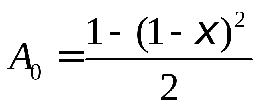
M \u003d R b * b * h 0 * A 0, kN * m |
||||
|
In the lower zone of the crossbar |
In the last span: at base A |
|
|
| |||||||
|
at support B |
|
|
| ||||||||
|
In the middle span: at support B |
|
|
| ||||||||
|
at support C |
|
|
| ||||||||
|
In the upper zone of the crossbar |
At base B: from the end span |
|
|
| |||||||
|
from the middle span |
|
|
| ||||||||
|
At support C from both sides |
|
|
| ||||||||


|
The location of the broken rods |
Longitudinal __ armature__ breakable reinforcement |
Transverse reinforcement _quantity_ |
Transverse force at the point of theoretical breakage of the rods, kN |
|
The length of the launch of broken rods beyond the place of the theoretical break, mm |
Minimum value w=20d |
Accepted value w, mm |
Distance from support axis, mm |
||
|
To the place of the theoretical break (according to the diagram of materials) |
To the actual break point |
|||||||||
|
In the lower zone of the crossbar |
In the last span: at base A |
|
| |||||||
|
at support B |
|
| ||||||||
|
In the middle span: at support B |
|
| ||||||||
|
at support C |
|
| ||||||||
|
In the upper zone of the crossbar |
At base B: from the end span |
|
| |||||||
|
from the middle span |
|
| ||||||||
|
At support C from both sides |
|
| ||||||||


