Routing designed for laying out and compacting bulk ASG when performing work on the site topography.
1.2. Organization and technology of work performance
The preparatory operations include: geodetic breakdown of the contours of the layout and the zero line with the installation of marking marks and benchmarks;
implementation of measures to protect the planned territory from the inflow of surface waters;
site lighting device;
arrangement of temporary access roads.
The main operations include:
arrangement of temporary earth-carrying roads within the planning site;
development of soil into a planning embankment;
backfilling of the AGM of the planning embankment with leveling of the AGM, moistening or drying with excessive moisture and compaction of the AGM.
Finishing operations include:
layout of the site and slopes of the excavation, slopes and top of the embankment.
Schemes for the production of works are given on l.6,7,8 of the graphic part.
When performing work on vertical planning, the soil of the planning excavation is partially transferred to the planning embankment.
The development of soft soil and loosened rock inclusions of the planning excavation is carried out by the B-10 bulldozer according to a tiered trench scheme with intermediate accumulation of AGM. The entire excavation is divided in depth into several tiers, each of which, in turn, is subdivided into 3 layers of 0.10 - 0.15 m each. ASG between trenches are leveled by a bulldozer after.
During the first penetration, moving towards the embankment, the bulldozer fills the ASG into the intermediate roller, during the second and third penetrations of the bulldozer, the intermediate roller is accumulated. Then the resulting large shaft of the ASG at one time collides down the slope into the backfilled embankment. Similarly, work is being carried out to develop the ASG of all three layers in the trench of each tier. The development of the ASG of the walls (lintels) left between the trenches is carried out after the development of the ASG in adjacent trenches. The ASG moved to the embankment is laid and leveled in layers 0.35 m thick.
Frozen ASG before the start of the work of the bulldozer, which produces the development of ASG, is loosened with a mounted ripper. Loosening is carried out in a cross way in two mutually perpendicular directions. First, longitudinal cuts are made to a depth of 0.30 m with a loosening step of 0.50 m, and then transverse cuts are made perpendicular to the longitudinal cuts with a depth of 0.30 m with a loosening step of 0.60 m. In this case, the effective loosening depth is 0.20 m Depth, loosening step are specified on the spot empirically.
The planning embankment is divided by area into two maps, where in technological sequence the following operations alternate:
backfilling and leveling of ASG with a bulldozer;
humidification of ASG;
aging and compaction of ASG with a Dynapac CA4000PD roller.
The ASG moved into the embankment by a bulldozer is leveled by the same bulldozer with circular penetrations when moving from the edges of the embankment to its middle. The passages of the bulldozer are carried out with the overlap of the previous penetration by 0.30 m. The ASG is leveled with a layer of 0.35 m. Watering is carried out depending on the required moisture in several steps. Each subsequent penetration of the watering machine is carried out after the CGM has absorbed water from the previous penetration.
Compaction of AGM should be carried out at the optimum moisture content in AGM. Rolling ASG is carried out from the edges of the card to its middle. The movement of the roller is carried out with the overlap of the track of the previous pass by 0.30 m. The first penetration of the roller is carried out at a distance of 3.00 m from the edge of the embankment, and then the edge of the embankment is rolled. After rolling the edges of the embankment, rolling is continued by circular passes of the roller in the direction from the edges of the embankment to its middle.
The value of the optimal humidity of the CGM, the required amount of water for additional humidification, required amount the passages of the roller along one track and the thickness of the laid layer are specified at the place of work by test rolling.
In the course of work on each layer of AGM, its compaction is monitored by sampling by a field soil laboratory.
For the movement of dump trucks, earth-carrying roads made of 0.30 m thick slag are provided. The slag brought by dump trucks is leveled by a B-10 bulldozer and compacted with a roller.
Earth-carrying roads along which ASG is transported by dump trucks must be constantly maintained in good condition.
Schemes for laying ASG with a bulldozer
a - "from oneself"; b - "for yourself"; in - "separate heaps"; g - "semi-pressed"; d - "press"
1.3. Compaction of ASG with a Dynapac CA4000PD roller
Prior to the beginning of the ASG compaction, it is necessary to deliver to the site and test the soil compaction mechanisms, inventory and devices necessary to carry out the work on the ASG compaction, and complete the preparation of the scope of work.
In large areas, when performing work on the vertical planning of the territory, the scheme of movement of the skating rink in a vicious circle should be used. On embankments, where the possibility of turning the rink and the device of entrances is excluded, a shuttle traffic pattern should be used.
The number of moves of the rink along one lane should be approximately taken within 3-4, then the number of passes of the rink along one track is set by the construction laboratory in accordance with the required design density of the ASG.
Experimental soil compaction of embankments and backfills is carried out and as a result the following should be established:
a) the thickness of the layers being poured, the number of passes of compacting machines along one track, the duration of the impact of vibration and other organs on the ASG and other technological parameters that ensure the design density of the ASG;
b) values of indirect indicators of compaction quality subject to operational control.
Types and physical and mechanical characteristics of ASGs intended for the construction of embankments and backfilling devices, and special requirements for them, the required degree of compaction (compaction coefficient - 0.95), the boundaries of the parts of the embankment erected from soils with different physical and mechanical characteristics are indicated in project.
Scheme of work on soil compaction with rollers 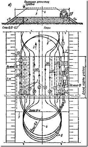
a - when turning the rink on the site; b - when turning the skating rink with a exit from the site; 1 - axes, numbers and directions of the rink passes; 2 - the general direction of work on rolling; 3 - overlapping of strips during rolling; 4 - embankment axis; 5-width of the embankment; 6 - turn of the rink; 1: t - steepness of embankment slopes
Scheme of organization of work on backfill compaction

Sealing ASG when working on linear sections

The optimal humidity of the CGM, if necessary, is achieved by moistening the dry ones and, conversely, draining the excessively moistened CGM.
When sealing ASG, the following conditions must be observed:
- the performance of self-propelled rollers must correspond to the performance of earth-moving and Vehicle;
- the thickness of the layer to be poured should not exceed the values specified in technical specifications self-propelled rollers;
- each subsequent stroke of the roller in order to avoid gaps in the compaction of the ASG should overlap the previous one by 0.15 ... 0.25 m.
Compaction of ASG by rolling should be carried out at a rational high-speed mode of operation of the rollers. The speeds of the roller are different, and the first and last two passes are made at low speeds (2 ... 2.5 km / h), and all intermediate passes - at high, but not exceeding 8 ... 10 km / h. With a rational high-speed operation of the rink, its productivity is approximately doubled.
In case of appearance ground water it is necessary to provide for the flow of water along the slope into the sumps with subsequent pumping out by pumps.
1.4. Scheme of operational quality control
The required quality of the compacted AGM layer is provided by the construction organization through the implementation of a set of technical, economic and organizational measures for effective control at all stages of the construction process.
Quality control of work should be carried out by specialists or special services that are part of construction organizations, or outsourced and equipped technical means providing the necessary reliability and completeness of control.
Production quality control of work on soil compaction by self-propelled rollers should include:
- incoming control of documentation for materials, namely the availability of a document on the quality of ASG containing information according to clause 4 of GOST 23735;
– operational control of individual construction processes or production operations;
- acceptance control of work performed.
During the input control of working documentation, its completeness and sufficiency of the technical information contained in it for the performance of work should be checked.
Used in the construction of embankments, backfilling devices, AGM must meet the requirements of the project, relevant standards and specifications. Replacement of the soils provided for by the project, which are part of the structure under construction or its foundation, is allowed only upon agreement with the design organization and the customer. The soil brought to the construction site, intended for vertical planning, backfilling of the sinuses of pits, backfilling of road troughs, etc., must have a conclusion on the sanitary-environmental and radiation examination.
Input control includes:
- checking the granulometric composition of the soil;
— checking for wood, fibrous materials, rotting and easily compressible debris, as well as soluble salts contained in the backfill and embankment soil;
- study and analysis of frozen clods contained in the AGM, the size of solid inclusions, the presence of snow and ice;
– determination of the AGM moisture content using the MG-44 soil moisture meter
The results of the input control must be entered in the "Journal of input accounting and quality control of the received parts, materials, structures and equipment."
Operational control is carried out in the course of construction processes and production operations and ensures the timely detection of defects and the adoption of measures to eliminate and prevent them. It is carried out by a measuring method or technical inspection. The results of operational control are recorded in the General work logs and work production logs, geodetic control logs and other documents provided for by the quality management system in place in the organization.
During operational control, they check: compliance with the technology for performing work on the compaction of AGM, their compliance with SNiP (correspondence to the type of machines adopted in the project for the production of work, the humidity and thickness of the AGM layer being poured, its uniformity in the backfill, the density of the AGM in the layers of the embankment, etc.).
Acceptance control - control performed upon completion of work on the sealing of the ASG at the facility or its stages with the participation of the customer. Acceptance control consists in a selective verification of the compliance of the parameters of the completed elements of an earthwork with normative and design ones and an assessment of the quality of the work performed. Acceptance earthworks should be to check:
- marks of the edges of the embankment and the pit;
- dimensions of the embankment;
- steepness of slopes;
- the degree of compaction of the ASG;
— quality of foundation soils.
When working on the compaction of the ASG, careful and systematic monitoring of:
- humidity of the compacted ASG with the help of the soil moisture meter "MG-44";
- the thickness of the poured layer of ASG;
- the number of passages of soil-compacting mechanized means along the soil;
- the speed of movement of soil-compacting mechanized means.
The quality of soil compaction work is ensured by workers, foremen, foremen and foremen. The main responsibility of the foreman, foreman and foreman is to ensure the high quality of work in accordance with the working drawings, the project for the production of work, SNiP and technological conditions for the production and acceptance of work.
The handover and acceptance of work is documented by acts of examination of hidden works, quality checks of compaction based on the results of tests performed by the laboratory with the attached test report. The acts must contain a list of technical documentation on the basis of which the work was performed, data on checking the correctness of the compaction and the bearing capacity of the base, as well as a list of deficiencies indicating the timing of their elimination.
The composition of controlled operations, deviations and methods of control
| Technical requirements | Limit deviations | Control (method and scope) |
| 1 | 2 | 3 |
| 1. Humidity of the sealed ASG | Should be within the limits set by the project | Measuring, according to the instructions of the project |
| 2.Surface seal: | ||
| a) the average density of the compacted soil over the accepted area | The same, not lower than the design. It is allowed to reduce the density of dry soil by 0.05 t / m 3 in no more than 10% of determinations | The same, according to the design instructions, and in the absence of instructions, one point per 300 m 2 of the compacted area with measurements within the entire compacted thickness through 0.25 m in depth with a compacted layer thickness of up to 1 m and after 0.5 m with a greater thickness; the number of samples at each point is at least two |
| b) the magnitude of the decrease in the surface of the AGM (failure) during compaction with heavy rammers | Should not exceed the value set during experimental compaction | Measuring, one determination per 300 m2 of compacted area |
Based on the results of the acceptance control, a documented decision is made on the suitability of the compacted soil for subsequent work
1.5. Control of embankment compaction by cutting ring method
The main control over the compaction of the embankment during the production process is carried out by comparing the volumetric weight of the soil skeleton taken from the embankment (g sk.), with optimal density (g sk. op.).
Sampling and determination of the volumetric weight of the soil skeleton in the embankment is carried out using a soil sampler, which consists of a lower part with a cutting ring and a striker.
Soil sampler

a - the lower part of the soil sampler; b - cutting ring (separately); in - drummer with a movable load
When sampling the soil, an assembled soil sampler is placed on its cleaned surface and hammered into the soil with a drummer. Then the cover and the intermediate ring of the lower part of the sampler are removed, the cutting ring is dug in, carefully removed along with the soil, the soil is cut off with a knife flush with the lower and upper edges of the ring. The ring with soil is weighed with an accuracy of one gram and the volumetric weight of wet soil in the embankment is determined by the formula:
![]()
Where G 1 is the mass of the ring, g;
G 2 - mass of the ring with soil, g;
V- ring crimp, cm 3.
This test is performed three times.
The humidity of the tested soil sample is also determined three times by drying a sample of 15–20 g taken from each ring with soil to a constant mass.
The volumetric weight of the soil skeleton of the embankment is determined by the formula:
![]()
Where Wow.- weight soil moisture in fractions of a unit.
The resulting volumetric weight of the skeleton in the embankment is compared with the optimal density of the same soil. Coefficient TO, characterizing the degree of soil compaction in the embankment, is determined by the formula:
1.6. Compaction control with soil moisture meter "MG-44"
PURPOSE
Electronic digital humidity meter "MG-44" (hereinafter referred to as the device), designed to measure relative humidity ground using a sensitive RF sensor.
Humidity is determined using an indirect measurement method based on the dependence of the dielectric properties of the medium on its humidity. An increase in the dielectric constant of the test sample, at a constant temperature, indicates an increase in the water content in the material.
The device is intended for operation in areas with a temperate climate. By protection from impact environment, the device has an ordinary design. In the ambient air at the installation site of the device, the presence of aggressive vapors and gases and vapors within the limits sanitary norms, according to the norms of SN-245-71.
TECHNICAL DATA
Range of relative soil moisture measured by the device, %: 1-100
The limit of the main absolute error in the entire range of humidity measurement, %: ±1 (90% of measurements fit within the specified error).
Operating mode establishment time, s: 3
Single measurement time, sec. max: 3
The device is powered from an internal source + -10 direct current+9 volts.
The reading of the measured relative humidity is made by a liquid crystal indicator located on the front panel of the indicator device.
Overall dimensions of the indicator device, mm: 145´80´40
Sensor: electrode length - 50 mm, sensor body length - 140 mm, diameter - 10 mm
Weight, kg, max: 0.3
Temperature of the analyzed soil: -20…+60°C.
Ambient temperature from -20 to +70°C.
The change in instrument readings from a change in ambient temperature for every 10°C relative to normal (20°C), in the range from +1°C to +40°C, does not exceed 0.2 of the basic absolute error.
Consumed electric power device, not more than 0.1 VA.
DEVICE AND OPERATION OF THE DEVICE
The general principle of operation of the device is as follows:
The sensor emits a directed electromagnetic wave of high frequency, part of which is absorbed by water molecules while propagating in the substance, and part is reflected in the direction of the sensor. By measuring the reflection coefficient of the wave from the substance, which is directly proportional to the water content, we display the relative humidity value on the indicator.
ORDER OF MEASUREMENT.
When measuring, immerse the electrode in the ground.
Turn on the device with the button located on the left side of the case.
On the display you will see: in the first line the name of the product of the first in the list of calibrations, in the second from the left - the value of humidity in%: "H = ....%", on the right - the battery charge indicator. By pressing the button with the arrow "Left", you go to the list calibrations stored in the memory of the device. Using the buttons "Left", "Right" select the line you need, press "Enter", - on the display the name of the product and its humidity.
You can make a correction (within + - 5% in 0.1% increments) to the readings of the device if the readings of the device and the moisture content of the product obtained by the laboratory air-thermal method do not match. To do this, follow the following procedure:
Immerse the sensor in soil whose moisture content is precisely known.
Press the power button
Select the line you need from the list.
Press Enter.
Press and hold the Up arrow button until the second line of the display shows the % correction value between the humidity reading and the battery symbol. For example:
Release the up arrow button.
Use the buttons to set the desired correction. Simultaneously with the correction at the bottom left, the humidity value, already corrected, also changes. After setting the desired value, press "Enter", and the correction value will disappear from the display.
The shape of the calibration curve does not change when a correction is made. There is only a parallel transfer of the characteristic "down" - "up" within +_ 5%.
The correction for each of the 99 channels is its own and independent.
Calibration
You can independently enter into the memory of the processor and create any calibration curve for any type of soil.
1. Press and hold the Up button
2. Without releasing the "Up" button, press and hold the power button all the time
On the display you will see:
Release the up arrow button
It is necessary to dial the calibration access code: 2-0-0-3
You do this procedure using the buttons “Left” (set from 1 to 9 and again from 1 to 9, each press increases the number by 1), “Right” (go to the next digit). By typing 2-0-0-3 , press “Enter”
3.On the display you will see:
U= ……V E= -.- -V
In the upper left corner is the current voltage value from the sensor. It varies depending on soil moisture. In the upper right is the voltage value already stored in the processor memory and corresponding to the value of soil moisture in % you typed in the H=….% line. If you see dashes in the upper right corner, it means that the humidity value at the bottom left has not yet been assigned a voltage value.
Before entering a new calibration, you must reset the memory.
Press and hold the button until the display shows:
Release the button and the memory is free for calibration on this channel.
This erases all previously entered data for this channel.
Completely immerse the sensor electrode in soil whose moisture content is precisely known.
Press the left or right arrow button
In the second line, the symbol H=0.0% will be enclosed on both sides in triangular cursors.
Enter the desired humidity value (humidity of the calibrated sample into which the electrode is inserted (in the line H = ....%)) using the arrows "Left" and "Right".
Press Enter. One point added. At the same time, in the upper right corner of the indicator in the line E = .... the voltage value of the sensor that has entered the permanent memory will appear. Minimal amount two points. The maximum is 99. The shape of the calibration characteristic is straight. The moisture values 0.99 and 100 cannot be entered. Enter 1 and 98.
Insert the sensor electrodes into another sample with a different moisture content (known) and repeat the procedure.
Accurate calibration is possible if you calibrate the instrument with samples whose moisture content lies at the edges of the range you are interested in.
For soil, usually 12 -70%%. Only whole numbers are entered. Humidity obtained by the air-thermal method must be rounded up to integers. The processor itself will build a calibration curve and display tenths.
If you do not want to erase the entire calibration from the memory, but only individual points, do the following procedure:
Enter the calibration mode and start pressing the "Left" button in sequence
When you get to a point stored in memory, in the upper line on the right in the expression E= -, - - V, instead of dashes, a voltage value appears, which corresponds to the moisture content in% typed in the bottom line (H= ....%). If you want to delete this point without erasing the rest of the information, press while in the expression E= ….,…. V instead of numbers, dashes will not appear. Release the button immediately so as not to erase the rest of the points. Mark the edges of the full range of work.
You can type (or change) any calibration name in any of the 99 lines using the Latin and Russian alphabets and Arabic numerals:
Turn on the device
Use the "Left", "Right" buttons to select the desired line.
Press and hold the Enter button until two lines appear:
One with alphabets and numbers, the other with the name you type.
In the line of alphabets, use the “Right”, “Left” buttons to select a letter or number (the character ready to be entered in the name line is enclosed between two arrows), press “Enter” and the symbol is saved on the name line. Erasing a previously typed word or an erroneous character with the “Up” button. One click - one erased sign.
When you have fully typed the name of the calibration, press “Enter” until you return to the list of calibrations with the name already saved.
1.7. Safety and labor protection
General instructions for safety in the production of earthworks are given in the technological map for the development of excavations.
Work areas in settlements or on the territory of the organization must be fenced to prevent access by unauthorized persons. Specifications according to the device of inventory fences, GOST 23407-78 is established.
The self-propelled skating rink must be equipped with sound and light signaling devices, the serviceability of which must be monitored by the driver. It is forbidden to work with faulty sound and light signaling devices or without them. Before starting the movement of the machine or when braking and stopping, the driver must give warning signals.
It is forbidden to work in the evening and at night in the absence of lighting or with insufficient visibility of the work front.
When working on soil compaction with self-propelled rollers, it is prohibited:
— work on faulty rollers;
- lubricate the roller on the go, troubleshoot, adjust the roller, enter and exit the roller cabin;
- leave the roller with the engine running;
- be in the cabin of the ice rink or in close proximity to it by unauthorized persons;
- be on the frame of the rink or between the rinks during their movement;
- stand in front of the disc with the locking ring when inflating tires;
- leave the rollers on a slope without placed stops under the rollers;
- turn on the vibrator when the vibratory roller is on solid ground or a solid foundation (concrete or stone).
When compacting soils at night, the machine must have overall light signals and headlights to illuminate the path of movement.
After finishing work, the driver must put the machine in the place allotted for its parking, turn off the engine, cut off the fuel supply, winter time drain the water from the cooling system to prevent it from freezing, clean the machine of dirt and oil, tighten the bolted connections, lubricate the rubbing parts. In addition, the driver must remove the starting devices, thereby eliminating any possibility of starting the machine. outsiders. When parking, the machine must be braked, and the control levers placed in the neutral position. When handing over a shift, it is necessary to inform the shifter about the condition of the machine and any malfunctions found.
In the production of soil compaction, measures must be taken to prevent overturning of machines or their spontaneous movement under the influence of wind or in the presence of a slope of the terrain. It is not allowed to use open fire to heat up the machine components, as well as to work on machines with leaks in the fuel and oil systems.
When compacting the soil with two or more self-propelled machines following one after the other, the distance between them must be at least 10 m.
Movement, installation and operation of a soil compactor near an excavation with unreinforced slopes is permitted only outside the limits established by the project for the production of works. In the absence of relevant instructions in the project for the production of works, the horizontal distances from the base of the slope of the excavation to the nearest supports of the machines must correspond to those indicated in the table
Liked this.
When choosing crushed stone, it is important to take into account such an indicator as the compaction coefficient. This criterion shows how much it is possible to reduce the volume of material, while maintaining the same mass due to tamping or natural shrinkage. This indicator is used to determine the amount of aggregate, both upon purchase and directly during the construction process.
In view of the fact that after ramming the bulk density of crushed stone of any fraction will increase, it is necessary to immediately take into account the stock of material. And in order not to buy too much, a correction factor is needed.

The compaction coefficient (Ku) is a very important indicator, which is necessary not only for correct compilation ordering materials, but also in order to provide for further shrinkage of the gravel layer after its loading building structures. Moreover, knowing the compaction coefficient, it is possible to predict the stability of the construction objects themselves. Due to the fact that the tamping factor is, in fact, the degree of volume reduction, it can vary depending on 4 factors:
- Loading method and parameters (for example, from what height backfilling is performed).
- Features of the transport by which the material is delivered to the object, and the distance to the construction site - after all, even a stationary mass gradually compacts as a result of subsidence under its own weight.
- Fractions of crushed stone and the content of grains of smaller size than the lower limit of a particular class of crushed stone.
- Flakiness - needle-shaped stones shrink less than cuboid ones.
It should be remembered that the strength of concrete structures, building foundations and highways directly depends on the accuracy of determining the degree of compaction. However, one should also not forget that tamping on the site is often carried out only on the top layer, and in this case the calculated coefficient does not always correspond to the actual shrinkage of the base. Especially often this happens when construction is not done by professionals, but by amateurs. In accordance with the requirements of the technology, each layer of backfill must be rolled and checked separately.

Another parameter that must be taken into account is that the degree of compaction is calculated for a mass that is compressed without lateral expansion, that is, it is limited by walls, which prevents it from spreading. At the site, such conditions for backfilling any fraction of crushed stone are not always created, so a small error remains. This fact should be taken into account, first of all, when calculating the settlement of large structures.
Transport seal
It should be noted that finding some standard value for compressibility is actually not easy, as too many factors affect it. (All of them are listed above). The supplier may indicate the crushed stone compaction factor in the accompanying documentation, although GOST 8267-93 does not directly require this. However, when transporting gravel, especially large batches, there is often a significant difference in the volumes when loaded and at the construction site where it was delivered. Therefore, the correction factor, which takes into account the compaction of crushed stone, must be entered into the contract and controlled at the reception point. The only mention in the current GOST: the compaction coefficient, regardless of the fraction, should not be higher than 1.1. Suppliers are certainly aware of this and are trying to keep a small stock in order to avoid returns. Measurements are often resorted to during acceptance, when crushed stone is delivered to the construction site, since it is ordered not in tons, but in cubic meters. To do this, the truck body with the crushed stone in it must be measured from the inside with a tape measure, then calculate the volume of delivered gravel, and then multiply it by a factor of 1.1. Such a calculation will allow you to approximately determine how many cubes were filled into the back of a truck before shipment. If the figure obtained taking into account the compaction is less than the one indicated in accompanying documents, means, the body of the car was underloaded. Equal to or greater than indicated in the documents - you can safely unload crushed stone.

Site compaction
It should be noted that the above figure - 1.1 - is taken into account only during transportation. At a construction site where crushed stone is compacted artificially, using a vibrating plate or a roller, this coefficient can increase to 1.52. At the same time, performers need to know exactly the degree of shrinkage of the gravel backfill. This setting is usually listed in project documentation. However, if there is no need for an exact value, they use the average indicators that are indicated in SNiP 3.06.03-85:
Crushed stone of fraction 40-70, as a rule, has a compaction of 1.25-1.3 (if its grade is not lower than M800). Up to M600 - from 1.3 to 1.5. For small and medium classes of 5-20 and 20-40 mm, these indicators have not been established, since they are often used only when buckling the upper bearing layer of grains 40-70.

Laboratory research
It is customary to calculate the compaction coefficient on the basis of laboratory test data, during which the mass of crushed stone is subjected to ramming and testing on various devices. There are several methods here: volume substitution (GOST 28514-90); standard layer-by-layer compaction of crushed stone (GOST 22733-2002); express methods using one of three types of density meters: static, water balloon or dynamic.
The results are obtained either immediately or after 1-4 days, depending on which method for the study is chosen. The cost of one sample of the standard test is 2500 rubles. In total, at least five such tests must be carried out. If data is needed urgently, for example, during the day, express methods are used based on the results of selecting at least 10 points. The cost of each point is 850 rubles. In addition, you will have to pay for the departure of the laboratory assistant to the site - about 3 thousand rubles more. However, one cannot do without accurate data on the construction of large facilities. In addition, a reputable construction organization must have official documents that confirm that the contractor complies with the requirements of the project.
Is it possible to find out the degree of tamping yourself?
Yes, the coefficient can be defined as in field conditions and for the needs of private construction. To do this, you must first find out the bulk density for each size: 5-20, 20-40, 40-70. It directly depends on the mineralogical composition of the material, but only slightly. Crushed stone fractions have a much greater influence on the volumetric weight. For the calculation, you can use averaged data:

More accurate density data for a specific fraction of crushed stone can be determined in the laboratory or by weighing a known volume building rubble followed by a simple calculation:
Bulk weight = mass / volume.
After that, the mixture is rolled to the state in which it will be used on the site, and measured with a tape measure. And then they again calculate the formula above, resulting in 2 different densities - before and after tamping. By dividing both numbers, we get the compaction coefficient for a particular material. With the same sample weight, you can simply find the ratio of the two volumes - the result will be the same. It should be noted that if the indicator after tamping is divided by the initial density, then the number obtained in the answer will be greater than one - in fact, this is the material safety factor for compaction. In construction, it is used if the final parameters of the gravel pad are known and for ordering it is necessary to determine the amount of crushed stone of the selected fraction. The reverse calculation results in a value less than one. However, these figures are equivalent and in the calculations it is important to understand which one should be taken.
The compaction factor must be determined and taken into account not only in the narrowly focused areas of construction. Specialists and ordinary workers performing standard procedures for the use of sand are constantly faced with the need to determine the coefficient.
The compaction factor is actively used to determine the volume of bulk materials, in particular sand,
but also applies to gravel, soil. The most accurate method for determining compaction is by weight.
wide practical use I did not find it due to the inaccessibility of equipment for weighing large volumes of material or the lack of sufficiently accurate indicators. Alternative option coefficient output - volumetric accounting.
Its only drawback is the need to determine the compaction on different stages. This is how the coefficient is calculated immediately after extraction, during storage, during transportation (relevant for road transport deliveries) and directly at the end consumer.
Factors and properties of building sand
The compaction coefficient is the dependence of the density, that is, the mass of a certain volume, of the controlled sample to the reference standard.
It should be borne in mind that all types of mechanical, external seals can only affect upper layer material.
The main types and methods of compaction and their effect on the upper layers of the soil are presented in the table.
To determine the volume of material to be backfilled, the relative compaction factor must be taken into account. It is related to the change physical properties excavation after sand excavation.
When pouring the foundation, it is necessary to know the correct proportions of sand and cement. By clicking on familiarize yourself with the proportions of cement and sand for the foundation.
Cement is special bulk material, which in its composition is a mineral powder. about different grades of cement and their application.
With the help of plaster, the thickness of the walls is increased, which increases their strength. find out how long the plaster dries.
P \u003d ((m - m1) * Pv) / m-m1 + m2-m3, Where:
- m is the mass of the pycnometer when filled with sand, g;
- m1 is the weight of an empty pycnometer, g;
- m2 is the mass with distilled water, g;
- m3 is the weight of the pycnometer with the addition of distilled water and sand, and after getting rid of air bubbles
- Pw - water density
In this case, several measurements are carried out, based on the number of samples provided for verification. Results should not differ by more than 0.02 g/cm3. In the case of large received data, the arithmetic mean is displayed.
Estimates and calculations of materials, their coefficients are the main component of the construction of any objects, as it helps to understand the quantity required material and, accordingly, costs.
For a correct estimate, it is necessary to know the density of the sand, for this, information provided by the manufacturer, based on surveys, and the relative compaction factor upon delivery are used.
Because of what the level of the loose mixture and the degree of compaction change
Sand passes through a rammer, not necessarily special, perhaps in the process of moving. It is quite difficult to calculate the amount of material obtained at the output, taking into account all the variables. For accurate calculation it is necessary to know all the impacts and manipulations carried out with sand.
The final coefficient and degree of compaction depends on various factors:
- method of transportation, the more mechanical contact with irregularities, the stronger the seal;
- route duration, information is available to the consumer;
- the presence of damage from mechanical influences;
- the amount of impurities. In any case, foreign components in the sand give it more or less weight. The cleaner the sand, the closer the density value to the reference;
- the amount of moisture that has entered.
Immediately after purchasing a batch of sand, it should be checked.
What samples are taken to determine the bulk density of sand for construction
You need to take samples:
- for a batch of less than 350 tons - 10 samples;
- for a batch of 350-700 tons - 10-15 samples;
- when ordering more than 700 tons - 20 samples.
Take the obtained samples to a research institution for examinations and comparison of quality with regulatory documents.
Conclusion
The required density is highly dependent on the type of work. In general, compaction is necessary for the formation of the foundation, backfilling of trenches, creating a pillow under the roadbed, etc. It is necessary to take into account the quality of tamping, each type of work has different requirements to seal.
In the construction of roads, a skating rink is often used; in places that are difficult to access for transport, a vibrating plate of various capacities is used.
So, to determine the final amount of material, it is necessary to lay down the compaction coefficient on the surface during tamping, this ratio is indicated by the manufacturer of tamping equipment.
Always the relative index of the density coefficient is taken into account, since soil and sand tend to change their performance based on the level of humidity, type of sand, fraction and other indicators.
In preparation for development, special studies and tests are carried out to determine the suitability of the site for the upcoming work: they take soil samples, calculate the level of groundwater occurrence and examine other soil features that help determine the possibility (or lack thereof) of construction.
The implementation of such measures contributes to the improvement of technical indicators, as a result of which a number of problems that arise during the construction process are solved, for example, subsidence of the soil under the weight of the structure with all the ensuing consequences. Its first external manifestation looks like the appearance of cracks on the walls, and in combination with other factors, to the partial or complete destruction of the object.
Compaction coefficient: what is it?
Soil compaction coefficient means a dimensionless indicator, which, in fact, is a calculation from the ratio of soil density / soil density max . The soil compaction coefficient is calculated taking into account geological indicators. Any of them, regardless of breed, are porous. It is permeated with microscopic voids that are filled with moisture or air. When the soil is worked out, the volume of these voids increases many times, which leads to an increase in the looseness of the rock.

Important! The density index of bulk rock is much less than the same characteristics of compacted soil.
It is the soil compaction coefficient that determines the need to prepare the site for construction. Based on these indicators, sand cushions are prepared for the foundation and its base, further compacting the soil. If this detail is missed, it can become caked and begin to sag under the weight of the structure.
Soil compaction performance
The soil compaction coefficient indicates the level of soil compaction. Its value varies from 0 to 1. For the base of the concrete strip foundation the norm is considered to be >0.98 points.
The specifics of determining the compaction factor
The density of the soil skeleton, when the subgrade is amenable to standard compaction, is calculated in the laboratory. circuit diagram The study consists in placing a soil sample in a steel cylinder, which is compressed under the influence of an external brute mechanical force - impacts of a falling weight.
Important! The highest indicators of soil density are observed in rocks with humidity slightly above the norm. This relationship is shown in the graph below.

Each subgrade has its own optimal moisture content, at which the maximum level of compaction is achieved. This indicator is also examined in the laboratory, giving the breed different humidity and comparing compaction performance.
Real data is the end result of research, measured at the end of all laboratory work.
Compaction Methods and Coefficient Calculations
Geographic location determines qualitative composition soils, each of which has its own characteristics: density, moisture content, ability to subside. Therefore, it is so important to develop a set of measures aimed at improving the qualitative characteristics for each type of soil.
You already know the concept of compaction factor, the subject of which is studied strictly in the laboratory. Such work is carried out by the relevant services. The soil compaction index determines the method of impact on the soil, as a result of which it will receive new strength characteristics. When doing this, it is important to consider the percentage of amplification applied to achieve the desired result. Based on this, the soil compaction coefficient is subtracted (table below).

Typology of soil compaction methods
There is a conditional system of subdivision of compaction methods, the groups of which are formed based on the method of achieving the goal - the process of removing oxygen from the soil layers at a certain depth. Thus, a distinction is made between superficial and in-depth research. Based on the type of study, experts select the system of equipment and determine the method of its application. Soil research methods are:
- static;
- vibration;
- percussion;
- combined.
Each type of equipment displays a method of applying force, such as an air roller.

Partially, such methods are used in small private construction, others exclusively in the construction of large-scale facilities, the construction of which is agreed with the local authorities, since some of these buildings can affect not only the given site, but also the surrounding objects.
Compaction coefficients and norms of SNiP
All operations related to construction are clearly regulated by law, therefore they are strictly controlled by the relevant organizations.
Soil compaction coefficients are determined by SNiP in paragraph 3.02.01-87 and SP 45.13330.2012. The actions described in the regulatory documents were updated and updated in 2013-2014. They describe seals for different kind soil and soil cushions used in the construction of foundations and buildings of various configurations, including underground ones.

How is the compaction factor determined?
The easiest way to determine the compaction coefficient of the soil is by the method of cutting rings: a metal ring of a selected diameter and a certain length is driven into the soil, during which the rock is tightly fixed inside the steel cylinder. After that, the mass of the device is measured on a scale, and at the end of the weighing, the weight of the ring is subtracted, obtaining a net mass of soil. This number is divided by the volume of the cylinder and the final density of the soil is obtained. After that, it is divided by the indicator of the maximum possible density and the calculated one is obtained - the compaction coefficient for this area.
Compaction Factor Calculation Examples
Consider the definition of the soil compaction coefficient using an example:
- the value of the maximum soil density - 1.95 g / cm 3;
- cutting ring diameter - 5 cm;
- cutting ring height - 3 cm.
It is necessary to determine the coefficient of soil compaction.
This practical task is much easier to handle than it might seem.
To begin with, the cylinder is completely driven into the ground, after which it is removed from the soil so that the internal space remains filled with earth, but no accumulation of soil was noted outside.
Using a knife, the soil is removed from the steel ring and weighed.
For example, the mass of soil is 450 grams, the volume of the cylinder is 235.5 cm 3. Having calculated according to the formula, we get the number 1.91g / cm 3 - the density of the soil, from which the soil compaction coefficient is 1.91 / 1.95 = 0.979.
The erection of any building or structure is a responsible process, which is preceded by an even more important moment in the preparation of the site to be built, the design of the proposed buildings, and the calculation of the total load on the soil. This applies to all, without exception, buildings that are designed for long-term operation, the life of which is measured in tens or even hundreds of years.


