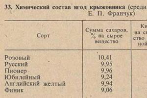
The topic of this article is thermal load. We will find out what this parameter is, what it depends on and how it can be calculated. In addition, the article will provide a number of reference values for thermal resistance different materials, which may be needed for calculations.
What it is
The term is essentially intuitive. Thermal load means the amount of thermal energy that is necessary to maintain a comfortable temperature in a building, apartment or separate room.
The maximum hourly heating load, therefore, is the amount of heat that may be required to maintain normalized parameters for an hour under the most unfavorable conditions.
Factors
So, what influences a building's heat demand?
- Wall material and thickness. It is clear that a wall of 1 brick (25 centimeters) and a wall made of aerated concrete under a 15-centimeter foam coat will transmit VERY different amounts of thermal energy.
- Roof material and structure. Flat roof from reinforced concrete slabs and an insulated attic will also differ very noticeably in heat loss.
- Ventilation is another important factor. Its performance and the presence or absence of a heat recovery system affect how much heat is lost in the exhaust air.
- Glazing area. Significantly more heat is lost through windows and glass facades than through solid walls.
However: triple glazed windows and glass with energy-saving coating reduce the difference several times.
- Insolation level in your region, absorption rate solar heat external covering and orientation of the building planes relative to the cardinal directions. Edge Cases- a house located all day long in the shade of other buildings and a house oriented with a black wall and a black sloping roof with a maximum area facing south.

- Temperature delta between indoors and outdoors determines the heat flow through the enclosing structures at constant resistance to heat transfer. At +5 and -30 outside, the house will lose different amounts of heat. This will, of course, reduce the need for thermal energy and reduce the temperature inside the building.
- Finally, it is often necessary to include in a project prospects for further construction. Let’s say, if the current heat load is 15 kilowatts, but in the near future it is planned to add an insulated veranda to the house, it is logical to purchase one with a reserve of heat power.
Distribution
In the case of water heating, the peak thermal power of the heat source must be equal to the sum of the thermal power of all heating devices in the house. Of course, wiring should not become a bottleneck either.
The distribution of heating devices throughout the premises is determined by several factors:
- The area of the room and the height of its ceiling;
- Location inside the building. Corner and end rooms lose more heat than those located in the middle of the house.
- Remoteness from the heat source. IN individual construction this parameter means the distance from the boiler in the system central heating apartment building- whether the battery is connected to the supply or return riser and what floor you live on.
Clarification: in houses with bottom filling, the risers are connected in pairs. On the supply side, the temperature decreases as you rise from the first floor to the last; on the return side, the opposite is true.

It’s also not difficult to guess how the temperatures will be distributed in the case of top filling.
- Desired room temperature. In addition to heat filtration through external walls, inside the building, with uneven temperature distribution, migration of thermal energy through partitions will also be noticeable.
- For living rooms in the middle of the building - 20 degrees;
- For living rooms in the corner or end of the house - 22 degrees. More heat, among other things, prevents walls from freezing.
- For the kitchen - 18 degrees. As a rule, it contains a large number of own heat sources - from a refrigerator to an electric stove.
- For a bathroom and a combined toilet, the norm is 25C.
In the case of air heating, the heat flow entering a separate room is determined by the throughput of the air hose. Usually, simplest method adjustments - manual adjustment of the positions of adjustable ventilation grilles with temperature control using a thermometer.
Finally, if we are talking about a heating system with distributed heat sources (electric or gas convectors, electric heated floors, infrared heaters and air conditioners), the required temperature regime is simply set on the thermostat. All that is required of you is to provide peak thermal power devices at the level of peak heat loss in the room.

Calculation methods
Dear reader, do you have a good imagination? Let's imagine a house. Let it be a log house made of 20-centimeter timber with an attic and a wooden floor.
Let’s mentally complete and concretize the picture that has arisen in our heads: the dimensions of the residential part of the building will be equal to 10*10*3 meters; We will cut 8 windows and 2 doors in the walls - to the front and inner courtyards. Now let’s place our house... say, in the city of Kondopoga in Karelia, where the temperature at the peak of frost can drop to -30 degrees.
Determining the heat load for heating can be done in several ways with varying complexity and reliability of the results. Let's use the three simplest ones.
Method 1
Current SNiPs offer us the simplest method of calculation. One kilowatt of thermal power is taken per 10 m2. The resulting value is multiplied by the regional coefficient:
- For the southern regions (Black Sea coast, Krasnodar region) the result is multiplied by 0.7 - 0.9.
- The moderately cold climate of the Moscow and Leningrad regions will force the use of a coefficient of 1.2-1.3. It seems that our Kondopoga will fall into this particular climate group.
- Finally, for the Far East regions of the Far North, the coefficient ranges from 1.5 for Novosibirsk to 2.0 for Oymyakon.
The instructions for calculating using this method are incredibly simple:
- The area of the house is 10*10=100 m2.
- The basic value of the thermal load is 100/10=10 kW.
- We multiply by the regional coefficient of 1.3 and get 13 kilowatts of thermal power necessary to maintain comfort in the house.

However: if you use such a simple technique, it is better to make a reserve of at least 20% to compensate for errors and extreme cold. Actually, it will be indicative to compare 13 kW with values obtained by other methods.
Method 2
It is clear that with the first calculation method the errors will be huge:
- Ceiling heights vary greatly between buildings. Taking into account the fact that we have to heat not an area, but a certain volume, and with convection heating warm air going under the ceiling is an important factor.
- Windows and doors let in more heat than walls.
- Finally, it would be a clear mistake to cut hair with one brush city apartment(and regardless of its location inside the building) and a private house, which has no below, above and behind the walls warm apartments neighbors, and the street.
Well, let's adjust the method.
- Let's take 40 watts per cubic meter of room volume as the base value.
- For each door leading to the street, add 200 watts to the base value. For each window - 100.
- For corner and end apartments in apartment building Let's introduce a coefficient of 1.2 - 1.3 depending on the thickness and material of the walls. We also use it for the outermost floors if the basement and attic are poorly insulated. For a private house, we will multiply the value by 1.5.
- Finally, we apply the same regional coefficients as in the previous case.

How is our house in Karelia doing?
- The volume is 10*10*3=300 m2.
- The basic value of thermal power is 300*40=12000 watts.
- Eight windows and two doors. 12000+(8*100)+(2*200)=13200 watts.
- A private house. 13200*1.5=19800. We begin to vaguely suspect that when selecting the boiler power using the first method, we would have to freeze.
- But there is still a regional coefficient left! 19800*1.3=25740. Total - we need a 28-kilowatt boiler. Difference from the first value obtained in a simple way- double.
However: in practice, such power will be required only on a few days of peak frost. Often, a reasonable solution would be to limit the power of the main heat source to a lower value and buy a backup heater (for example, an electric boiler or several gas convectors).
Method 3
Make no mistake: the described method is also very imperfect. We very roughly took into account the thermal resistance of the walls and ceiling; The temperature delta between internal and external air is also taken into account only in the regional coefficient, that is, very approximately. The price of simplifying calculations is a large error.
Let us remember: to maintain a constant temperature inside the building, we need to provide an amount of thermal energy equal to all losses through the building envelope and ventilation. Alas, here too we will have to somewhat simplify our calculations, sacrificing the reliability of the data. Otherwise, the resulting formulas will have to take into account too many factors that are difficult to measure and systematize.

The simplified formula looks like this: Q=DT/R, where Q is the amount of heat that is lost by 1 m2 of the building envelope; DT is the temperature delta between the internal and external temperatures, and R is the heat transfer resistance.
Please note: we are talking about heat loss through the walls, floor and ceiling. On average, another 40% of heat is lost through ventilation. To simplify the calculations, we will calculate the heat loss through the enclosing structures, and then simply multiply them by 1.4.
Temperature delta is easy to measure, but where do you get thermal resistance data?
Alas, only from reference books. Here is a table for some popular solutions.
- A wall of three bricks (79 centimeters) has a heat transfer resistance of 0.592 m2*C/W.
- A wall of 2.5 bricks is 0.502.
- Wall with two bricks - 0.405.
- Brick wall (25 centimeters) - 0.187.
- A log house with a log diameter of 25 centimeters is 0.550.
- The same, but from logs with a diameter of 20 cm - 0.440.
- Log house made of 20 cm timber - 0.806.
- Log frame made of timber 10 cm thick - 0.353.
- Frame wall 20 centimeters thick with insulation mineral wool — 0,703.
- A wall made of foam or aerated concrete with a thickness of 20 centimeters is 0.476.
- The same, but with a thickness increased to 30 cm - 0.709.
- Plaster 3 centimeters thick - 0.035.
- Ceiling or attic floor — 1,43.
- Wooden floor - 1.85.
- Double door made of wood - 0.21.

Now let's go back to our house. What parameters do we have?
- The temperature delta at the peak of frost will be equal to 50 degrees (+20 inside and -30 outside).
- Heat loss through a square meter of floor will be 50/1.85 (heat transfer resistance of a wooden floor) = 27.03 watts. Across the entire floor - 27.03*100=2703 watts.
- Let's calculate the heat loss through the ceiling: (50/1.43)*100=3497 watts.
- The area of the walls is (10*3)*4=120 m2. Since our walls are made of 20-centimeter timber, the R parameter is 0.806. Heat loss through the walls is equal to (50/0.806)*120=7444 watts.
- Now let’s add up the resulting values: 2703+3497+7444=13644. This is exactly how much our house will lose through the ceiling, floor and walls.
Note: in order not to calculate fractions square meters, we neglected the difference in thermal conductivity of walls and windows and doors.
- Then we add 40% of losses for ventilation. 13644*1.4=19101. According to this calculation, a 20-kilowatt boiler should be enough for us.
Conclusions and problem solving
As you can see, the available methods for calculating the thermal load with your own hands give very significant errors. Fortunately, excess boiler power won't hurt:
- Gas boilers operate at reduced power with virtually no drop in efficiency, while condensing boilers even reach the most economical mode at partial load.
- The same applies to solar boilers.
- Electric heating equipment of any type always has an efficiency of 100 percent (of course, this does not apply to heat pumps). Remember physics: all power not spent on mechanical work (that is, moving mass against the gravity vector) is ultimately spent on heating.
The only type of boilers for which operation at a power less than rated is contraindicated is solid fuel. The power control in them is carried out in a rather primitive way - by limiting the flow of air into the firebox.
What is the result?
- If there is a lack of oxygen, the fuel does not burn completely. More ash and soot are produced, which pollute the boiler, chimney and atmosphere.
- The consequence of incomplete combustion is a drop in boiler efficiency. It’s logical: after all, fuel often leaves the boiler before it burns.

However, here too there is a simple and elegant way out - including a heat accumulator in the heating circuit. A thermally insulated tank with a capacity of up to 3000 liters is connected between the supply and return pipelines, disconnecting them; in this case, a small contour is formed (between the boiler and the buffer tank) and a large one (between the tank and the heating devices).
How does this scheme work?
- After lighting, the boiler operates at rated power. Moreover, due to natural or forced circulation its heat exchanger transfers heat to the buffer tank. After the fuel has burned out, circulation in the small circuit stops.
- For the next few hours, the coolant moves along a large circuit. The buffer tank gradually releases the accumulated heat to radiators or water-heated floors.

Conclusion
As always, you will find some additional information on how else the heat load can be calculated in the video at the end of the article. Warm winters!
q - specific heating characteristic building, kcal/mh °C is taken from the reference book depending on the external volume of the building.
a is a correction factor taking into account the climatic conditions of the region for the city of Moscow, a = 1.08.
V is the external volume of the building, m determined from construction data.
t - average indoor air temperature, °C is taken depending on the type of building.
t - design temperature of outside air for heating, °C for Moscow t= -28 °C.
Source: http://vunivere.ru/work8363
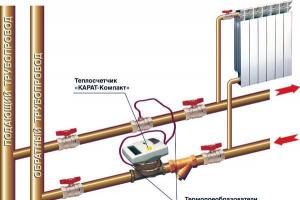
Q ych is composed of the thermal loads of devices served by water flowing through the area:![]() (3.1)
(3.1)
For a section of the supply heat pipeline, the thermal load expresses the heat reserve in the flowing hot water, intended for subsequent (on the further path of the water) heat transfer to the premises. For the section of the return heat pipeline - heat loss by flowing cooled water during heat transfer to the premises (on the previous water path). The thermal load of the site is intended to determine the water flow on the site during the hydraulic calculation process.
Water consumption on site G uch at the calculated difference in water temperature in the system t g - t x taking into account additional heat supply to the premises
where Q ych is the thermal load of the area, found by formula (3.1);
β 1 β 2 - correction factors taking into account additional heat supply to the premises;
c is the specific mass heat capacity of water, equal to 4.187 kJ/(kg°C).
To obtain the water consumption at the site in kg/h thermal load in W should be expressed in kJ/h, i.e. multiply by (3600/1000)=3.6.
generally equal to the sum of the thermal loads of all heating devices (heat loss in the premises). Based on the total heat demand for heating the building, the water consumption in the heating system is determined.Hydraulic calculation is associated with thermal calculation of heating devices and pipes. Multiple repetitions of calculations are required to determine the actual flow rate and temperature of water and the required area of the devices. When calculating manually, first perform a hydraulic calculation of the system, taking the average values of the coefficient of local resistance (LMC) of devices, then - thermal calculation of pipes and devices.
If the system uses convectors, the design of which includes pipes Dy15 and Dy20, then for a more accurate calculation, the length of these pipes is first determined, and after a hydraulic calculation, taking into account pressure losses in the pipes of the devices, specifying the flow rate and water temperature, amendments are made to the dimensions of the devices.
Source: http://teplodoma.com.ua/1/gidravliheskiy_rashet/str_19.html
In this section you will be able to familiarize yourself in as much detail as possible with issues related to the calculation of heat losses and thermal loads of a building.
The construction of heated buildings without calculating heat losses is prohibited!*)
And although the majority still build at random, on the advice of a neighbor or godfather. It is correct and clear to start at the stage of developing a detailed design for construction. How it's done?
The architect (or the developer himself) provides us with a list of “available” or “priority” materials for arranging the walls, roof, foundation, what windows and doors are planned.
Already at the stage of designing a house or building, as well as for selecting heating, ventilation, and air conditioning systems, you need to know heat losses building.
Calculation of heat loss for ventilation we often use in our practice to calculate the economic feasibility of modernizing and automating the ventilation / air conditioning system, because calculation of heat losses for ventilation gives a clear idea of the benefits and payback period of funds invested in energy-saving measures (automation, use of recovery, insulation of air ducts, frequency controllers).
Calculation of building heat losses
This is the basis for competent selection of the power of heating equipment (boiler, boiler) and heating devices
The main heat losses of a building usually occur on the roof, walls, windows and floors. Enough most of heat leaves the premises through the ventilation system.
Rice. 1 Heat loss of the building
The main factors influencing heat loss in a building are the difference in temperatures indoors and outdoors (than more difference, the greater the body loss) and the thermal insulation properties of enclosing structures (foundation, walls, ceilings, windows, roofing).
Fig.2 Thermal imaging of building heat losses
The materials of the enclosing structures prevent the penetration of heat from the premises outside in winter and the penetration of heat into the premises in the summer, because the selected materials must have certain thermal insulation properties, which are indicated by a value called - heat transfer resistance.
The resulting value will show what the real temperature difference will be when a certain amount of heat passes through 1 m² of a specific building envelope, as well as how much heat will be lost through 1 m² at a certain temperature difference.
#image.jpgHow to calculate heat losses
When calculating the heat losses of a building, we will mainly be interested in all external enclosing structures and the location of internal partitions.
To calculate heat losses along the roof, it is also necessary to take into account the shape of the roof and the presence of an air gap. There are also some nuances in the thermal calculation of the floor of a room.
In order to obtain the most accurate value of the heat loss of a building, it is necessary to take into account absolutely all enclosing surfaces (foundation, floors, walls, roofing), their constituent materials and the thickness of each layer, as well as the position of the building relative to the cardinal points and climatic conditions in the given region.
To order a heat loss calculation you need fill out our questionnaire and we will send our commercial offer to the specified postal address as soon as possible (no more than 2 business days).
Scope of work for calculating the thermal loads of a building
The main composition of the documentation for calculating the thermal load of a building:
- calculation of building heat losses
- calculation of heat losses for ventilation and infiltration
- permitting documentation
- summary table of thermal loads
The cost of calculating the thermal loads of a building
The cost of services for calculating the thermal loads of a building does not have a single price; the price for the calculation depends on many factors:
- heated area;
- availability of design documentation;
- architectural complexity of the object;
- composition of enclosing structures;
- number of heat consumers;
- diversity of purpose of premises, etc.
Finding out the exact cost and ordering a service for calculating the thermal load of a building is not difficult; to do this, you just need to send us a floor plan of the building by email (form), fill out a short questionnaire and after 1 business day you will receive our commercial offer to your mailbox.
#image.jpgExamples of the cost of calculating thermal loads
Thermal calculations for a private house
Documentation set:
- calculation of heat losses (room by room, floor by floor, infiltration, total)
- calculation of the thermal load for heating hot water(DHW)
- calculation for heating air from the street for ventilation
A package of thermal documents will cost in this case - 1600 UAH
To such calculations bonus You are getting:
Recommendations for insulation and elimination of cold bridges
Selection of main equipment power
_____________________________________________________________________________________
The sports complex is a separate 4-storey building of standard construction, with a total area of 2100 sq.m. with a large gym, heated supply and exhaust ventilation system, radiator heating, complete set documentation - 4200.00 UAH.
_____________________________________________________________________________________
The store is a building built into a residential building on the 1st floor, with a total area of 240 sq. m. of which 65 sq.m. warehouse premises, without basement, radiator heating, heated supply and exhaust ventilation with recovery - 2600.00 UAH.
______________________________________________________________________________________
Timeframes for completing work on calculating thermal loads
The duration of work to calculate the thermal loads of a building mainly depends on the following components:
- total heated area of premises or building
- architectural complexity of the object
- complexity or multi-layered enclosing structures
- number of heat consumers: heating, ventilation, hot water supply, other
- multifunctional premises (warehouse, offices, sales area, residential, etc.)
- organization of a commercial heat metering unit
- completeness of documentation (heating, ventilation design, as-built diagrams for heating, ventilation, etc.)
- diversity of use of building envelope materials during construction
- complexity of the ventilation system (recuperation, automatic control system, zone temperature control)
In most cases, for a building with a total area of no more than 2000 sq. m. The period for calculating the thermal loads of a building is from 5 to 21 working days depending on the above characteristics of the building, provided documentation and engineering systems.
Coordination of calculation of heat loads in heating networks
After completing all work on calculating thermal loads and collecting all necessary documents We are approaching the final, but difficult issue of coordinating the calculation of heat loads in urban heating networks. This process is a “classic” example of communication with a government agency, notable for a lot of interesting innovations, clarifications, views, interests of the subscriber (client) or a representative of a contractor (who has undertaken to coordinate the calculation of heat loads in heating networks) with representatives of city heating networks. In general, the process is often difficult, but surmountable.
The list of documentation provided for approval looks approximately like this:
- Application (written directly in heating networks);
- Calculation of thermal loads (in full);
- License, list of licensed works and services of the contractor performing the calculations;
- Technical passport for a building or premises;
- Legal documentation establishing ownership of the object, etc.
Usually for deadline for approval of thermal load calculations Accepted - 2 weeks (14 working days) subject to submission of documentation in full and in the required form.
Services for calculating building thermal loads and related tasks
When concluding or re-issuing an agreement for the supply of heat from city heating networks or designing and installing a commercial heat metering unit, heating networks notify the owner of the building (premises) of the need:- get technical specifications(THAT);
- provide a calculation of the building’s thermal load for approval;
- heating system project;
- ventilation system project;
- and etc.
We offer our services for carrying out the necessary calculations, designing heating and ventilation systems and subsequent approvals in city heating networks and other regulatory authorities.
You will be able to order either a separate document, project or calculation, or execution of all necessary documents on a turnkey basis from any stage.
Discuss the topic and leave feedback: "CALCULATION OF HEAT LOSSES AND LOADS" on FORUM #image.jpg
We will be glad to continue cooperation with you, offering:
Supply of equipment and materials at wholesale prices
Design work
Assembly / installation / commissioning works
Further maintenance and provision of services at reduced prices (for regular customers)
Whether it is an industrial building or a residential building, you need to carry out competent calculations and draw up a diagram of the heating system circuit. At this stage, experts recommend paying special attention to calculating the possible thermal load on the heating circuit, as well as the volume of fuel consumed and heat generated.
Thermal load: what is it?
This term refers to the amount of heat given off. A preliminary calculation of the thermal load will allow you to avoid unnecessary costs for the purchase of heating system components and their installation. Also, this calculation will help to correctly distribute the amount of heat generated economically and evenly throughout the building.
There are many nuances involved in these calculations. For example, the material from which the building is built, thermal insulation, region, etc. Experts try to take into account as many factors and characteristics as possible to obtain a more accurate result.
Calculation of heat load with errors and inaccuracies leads to inefficient operation of the heating system. It even happens that you have to redo sections of an already working structure, which inevitably leads to unplanned expenses. And housing and communal services organizations calculate the cost of services based on data on heat load.
Main Factors
An ideally calculated and designed heating system should maintain the set temperature in the room and compensate for the resulting heat losses. When calculating the heat load on the heating system in a building, you need to take into account:
Purpose of the building: residential or industrial.
Characteristics structural elements buildings. These are windows, walls, doors, roof and ventilation system.
Dimensions of the home. The larger it is, the more powerful the heating system should be. It is imperative to take into account the area of window openings, doors, external walls and the volume of each internal room.
Availability of special purpose rooms (bath, sauna, etc.).
Level of equipment technical devices. That is, the availability of hot water supply, ventilation system, air conditioning and type of heating system.
For a separate room. For example, in rooms intended for storage, it is not necessary to maintain a temperature that is comfortable for humans.
Number of hot water supply points. The more there are, the more the system is loaded.
Area of glazed surfaces. Rooms with French windows lose a significant amount of heat.
Additional terms and conditions. In residential buildings this may be the number of rooms, balconies and loggias and bathrooms. In industrial - the number of working days in a calendar year, shifts, technological chain of the production process, etc.
Climatic conditions of the region. When calculating heat loss, street temperatures are taken into account. If the differences are insignificant, then a small amount of energy will be spent on compensation. While at -40 o C outside the window it will require significant expenses.

Features of existing methods
The parameters included in the calculation of the thermal load are found in SNiPs and GOSTs. They also have special heat transfer coefficients. From the passports of the equipment included in the heating system, we take digital specifications, relating to a specific heating radiator, boiler, etc. And also traditionally:
Heat consumption, taken to the maximum per hour of operation of the heating system,
The maximum heat flow emanating from one radiator is
Total heat consumption in a certain period (most often a season); if hourly load calculation is required heating network, then the calculation must be carried out taking into account the temperature difference during the day.
The calculations made are compared with the heat transfer area of the entire system. The indicator turns out to be quite accurate. Some deviations do happen. For example, for industrial buildings it will be necessary to take into account the reduction in thermal energy consumption on weekends and holidays, and in residential premises - at night.
Methods for calculating heating systems have several degrees of accuracy. To reduce the error to a minimum, it is necessary to use rather complex calculations. Less accurate schemes are used if the goal is not to optimize the costs of heating system.
Basic calculation methods
Today, the calculation of the heat load for heating a building can be carried out using one of the following methods.

Three main
- For calculations, aggregated indicators are taken.
- The indicators of the structural elements of the building are taken as the basis. Here, the calculation of the internal volume of air used for heating will also be important.
- All objects included in the heating system are calculated and summed up.
One example
There is also a fourth option. It has a fairly large error, because the indicators taken are very average, or there are not enough of them. This formula is Q from = q 0 * a * V H * (t EN - t NRO), where:
- q 0 - specific thermal characteristic of the building (most often determined by the coldest period),
- a - correction factor (depends on the region and is taken from ready-made tables),
- V H is the volume calculated along the external planes.
Example of a simple calculation
For a building with standard parameters(ceiling heights, room sizes and good thermal insulation characteristics) you can apply a simple ratio of parameters adjusted for a coefficient depending on the region.
Let's assume that a residential building is located in the Arkhangelsk region, and its area is 170 square meters. m. The heat load will be equal to 17 * 1.6 = 27.2 kW/h.
This definition of thermal loads does not take into account many important factors. For example, design features buildings, temperatures, number of walls, ratio of wall areas to window openings, etc. Therefore, such calculations are not suitable for serious heating system projects.
It depends on the material from which they are made. The most commonly used today are bimetallic, aluminum, steel, much less often cast iron radiators. Each of them has its own heat transfer (thermal power) indicator. Bimetallic radiators with a distance between the axes of 500 mm, on average they have 180 - 190 W. Aluminum radiators have almost the same performance.

The heat transfer of the described radiators is calculated per section. Steel plate radiators are non-separable. Therefore, their heat transfer is determined based on the size of the entire device. For example, the thermal power of a double-row radiator with a width of 1,100 mm and a height of 200 mm will be 1,010 W, and panel radiator made of steel with a width of 500 mm and a height of 220 mm will amount to 1,644 W.
The calculation of a heating radiator by area includes the following basic parameters:
Ceiling height (standard - 2.7 m),
Thermal power (per sq. m - 100 W),
One external wall.
These calculations show that for every 10 sq. m requires 1,000 W of thermal power. This result is divided by the thermal output of one section. The answer is required amount radiator sections.
For the southern regions of our country, as well as for the northern ones, decreasing and increasing coefficients have been developed.
Average calculation and accurate
Taking into account the described factors, the average calculation is carried out according to the following scheme. If per 1 sq. m requires 100 W of heat flow, then a room of 20 sq. m should receive 2,000 watts. A radiator (popular bimetallic or aluminum) of eight sections produces about Divide 2,000 by 150, we get 13 sections. But this is a rather enlarged calculation of the thermal load.
The exact one looks a little scary. Nothing complicated really. Here's the formula:
Q t = 100 W/m 2 × S(room)m 2 × q 1 × q 2 × q 3 × q 4 × q 5 × q 6 × q 7, Where:
- q 1 - type of glazing (regular = 1.27, double = 1.0, triple = 0.85);
- q 2 - wall insulation (weak or absent = 1.27, wall laid with 2 bricks = 1.0, modern, high = 0.85);
- q 3 - the ratio of the total area of window openings to the floor area (40% = 1.2, 30% = 1.1, 20% - 0.9, 10% = 0.8);
- q 4 - street temperature (the minimum value is taken: -35 o C = 1.5, -25 o C = 1.3, -20 o C = 1.1, -15 o C = 0.9, -10 o C = 0.7);
- q 5 - number of external walls in the room (all four = 1.4, three = 1.3, corner room= 1.2, one = 1.2);
- q 6 - type of calculation room above the calculation room (cold attic = 1.0, warm attic = 0.9, heated residential room = 0.8);
- q 7 - ceiling height (4.5 m = 1.2, 4.0 m = 1.15, 3.5 m = 1.1, 3.0 m = 1.05, 2.5 m = 1.3).
Using any of the described methods, you can calculate the heat load of an apartment building.

Approximate calculation
The conditions are as follows. The minimum temperature in the cold season is -20 o C. Room 25 sq. m. m with triple glazing, double-glazed windows, ceiling height of 3.0 m, two-brick walls and an unheated attic. The calculation will be as follows:
Q = 100 W/m 2 × 25 m 2 × 0.85 × 1 × 0.8(12%) × 1.1 × 1.2 × 1 × 1.05.
The result, 2,356.20, is divided by 150. As a result, it turns out that 16 sections need to be installed in a room with the specified parameters.
If calculation in gigacalories is required
In the absence of a thermal energy meter on an open heating circuit, the calculation of the heat load for heating the building is calculated using the formula Q = V * (T 1 - T 2) / 1000, where:
- V - the amount of water consumed by the heating system, calculated in tons or m 3,
- T 1 - a number indicating the temperature of hot water, measured in o C and for calculations the temperature corresponding to a certain pressure in the system is taken. This indicator has its own name - enthalpy. If it is not possible to take temperature readings in a practical way, they resort to an averaged reading. It is within 60-65 o C.
- T 2 - temperature cold water. It is quite difficult to measure it in the system, so constant indicators have been developed that depend on the temperature outside. For example, in one of the regions, in the cold season this indicator is taken equal to 5, in the summer - 15.
- 1,000 is the coefficient for obtaining the result immediately in gigacalories.
In the case of a closed circuit, the heat load (gcal/hour) is calculated differently:
Q from = α * q o * V * (t in - t n.r.) * (1 + K n.r.) * 0.000001, Where

The calculation of the heat load turns out to be somewhat enlarged, but this is the formula given in the technical literature.
Increasingly, in order to increase the efficiency of the heating system, they are resorting to buildings.
This work is carried out in the dark. For a more accurate result, you need to observe the temperature difference between indoors and outdoors: it should be at least 15 o. Fluorescent and incandescent lamps turn off. It is advisable to remove carpets and furniture as much as possible; they knock down the device, causing some error.
The survey is carried out slowly and data is recorded carefully. The scheme is simple.

The first stage of work takes place indoors. The device is moved gradually from doors to windows, paying attention Special attention corners and other joints.
The second stage - inspection with a thermal imager external walls buildings. The joints are still carefully examined, especially the connection with the roof.
The third stage is data processing. First, the device does this, then the readings are transferred to the computer, where the corresponding programs complete the processing and produce the result.
If the survey was carried out by a licensed organization, it will issue a report with mandatory recommendations based on the results of the work. If the work was carried out in person, then you need to rely on your knowledge and, possibly, the help of the Internet.
In houses that were commissioned in last years, usually these rules are met, so the heating power of the equipment is calculated on the basis of standard coefficients. Individual calculations can be carried out at the initiative of the homeowner or the utility structure involved in the supply of heat. This happens when spontaneous replacement of heating radiators, windows and other parameters occurs.
 In an apartment served by a utility company, the calculation of the heat load can only be carried out upon transfer of the house in order to track the SNIP parameters in the premises accepted for balance. Otherwise, the apartment owner does this to calculate his heat loss during the cold season and eliminate insulation deficiencies - use heat-insulating plaster, glue insulation, install penofol on the ceilings and install metal-plastic windows with a five-chamber profile.
Calculating heat leaks for a utility for the purpose of opening a dispute, as a rule, does not yield results. The reason is that there are heat loss standards. If the house is put into operation, then the requirements are met. At the same time, heating devices comply with the requirements of SNIP. Replacing batteries and extracting more heat is prohibited, since radiators are installed according to approved building standards.
Private houses are heated autonomous systems, that in this case the load calculation  is carried out to comply with SNIP requirements, and heating power adjustments are carried out in conjunction with work to reduce heat loss.
Calculations can be done manually using a simple formula or a calculator on the website. The program helps to calculate the required power of the heating system and heat leakage typical for the winter period. Calculations are carried out for a specific thermal zone.
Basic principles
The technique includes whole line indicators that together make it possible to assess the level of insulation of the house, compliance with SNIP standards, as well as the power of the heating boiler. How it works:

An individual or average calculation is carried out for the object. The main point of conducting such a survey is that when good insulation and small heat leaks in winter, you can use 3 kW. In a building of the same area, but without insulation, at low winter temperatures the power consumption will be up to 12 kW. Thus, thermal power and load are assessed not only by area, but also by heat loss.
The main heat losses of a private house:
- windows – 10-55%;
- walls – 20-25%;
- chimney – up to 25%;
- roof and ceiling – up to 30%;
- low floors – 7-10%;
- temperature bridge in the corners – up to 10%
These indicators can vary for the better and for the worse. They are evaluated depending on the types installed windows, thickness of walls and materials, degree of ceiling insulation. For example, in poorly insulated buildings, heat loss through the walls can reach 45% percent; in this case, the expression “we are drowning the street” is applicable to the heating system. Methodology and  The calculator will help you estimate nominal and calculated values.
Specifics of calculations
This technique can also be found under the name “thermal engineering calculation”. The simplified formula is as follows:
Qt = V × ∆T × K / 860, where
V – room volume, m³;
∆T – maximum difference indoors and outdoors, °C;
K – estimated heat loss coefficient;
860 – conversion factor in kW/hour.
The heat loss coefficient K depends on building structure, thickness and thermal conductivity of walls. For simplified calculations, you can use the following parameters:
- K = 3.0-4.0 – without thermal insulation (non-insulated frame or metal structure);
- K = 2.0-2.9 – low thermal insulation (masonry in one brick);
- K = 1.0-1.9 – average thermal insulation ( brickwork two bricks);
- K = 0.6-0.9 – good thermal insulation according to the standard.
These coefficients are averaged and do not allow one to estimate heat loss and heat load on the room, so we recommend using an online calculator.
There are no posts on this topic.
When designing heating systems for all types of buildings, you need to carry out the correct calculations and then develop a competent diagram heating circuit. At this stage, special attention should be paid to calculating the heat load for heating. To solve the problem, it is important to use an integrated approach and take into account all the factors affecting the operation of the system.
- Thermal characteristics of the building are 0.49 W/m³*C.
- Clarifying coefficient - 1.
- The optimal temperature inside the building is 22 degrees.
- Optimal temperature parameters in rooms.
- The total area of the building.
- Outside air temperature.
- The area and thickness of the walls is 290 m² and 0.4 m.
- The building has windows (double glazing with argon) - 45 m² (R = 0.76 m²*C/W).
- The walls are made of solid brick - λ=0.56.
- The building was insulated with expanded polystyrene - d = 110 mm, λ = 0.036.
Show all
Parameter importance
Using the heat load indicator, you can find out the amount of heat energy required to heat a specific room, as well as the building as a whole. The main variable here is the power of all heating equipment that is planned to be used in the system. In addition, it is necessary to take into account the heat loss of the house.
The ideal situation seems to be in which the power of the heating circuit allows not only to eliminate all losses of heat energy from the building, but also to ensure comfortable conditions accommodation. To correctly calculate the specific heat load, it is necessary to take into account all the factors influencing this parameter:

The optimal operating mode of the heating system can only be determined taking these factors into account. The unit of measurement for the indicator can be Gcal/hour or kW/hour.
heating load calculation


Selecting a Method
Before you start calculating the heating load using aggregated indicators, you need to decide on the recommended temperature conditions for a residential building. To do this, you will have to refer to SanPiN 2.1.2.2645−10. Based on the data specified in this regulatory document, it is necessary to ensure operating modes of the heating system for each room.
The methods used today for calculating the hourly load on the heating system allow obtaining results of varying degrees of accuracy. In some situations, complex calculations may be required to minimize the error.
If, when designing a heating system, optimizing energy costs is not a priority, less precise methods can be used.
Calculation of thermal load and design of heating systems Audytor OZC + Audytor C.O.


Simple ways
Any method for calculating the thermal load allows you to select optimal parameters heating systems. This indicator also helps determine the need for work to improve the thermal insulation of a building. Today, two fairly simple methods for calculating the heat load are used.


Depending on the area

 If all rooms in the building have standard sizes and have good thermal insulation, you can use the method of calculating the required power of heating equipment depending on the area. In this case, 1 kW of thermal energy should be produced for every 10 m2 of room. Then the result must be multiplied by the correction factor of the climate zone.
This is the simplest method of calculation, but it has one serious drawback - the error is very high. During calculations, only the climate region is taken into account. However, many factors influence the efficiency of a heating system. Therefore, this technique is not recommended in practice.
Aggregated calculations
By applying the methodology for calculating heat using aggregated indicators, the calculation error will be smaller. This method was first often used to determine the heat load in situations where the exact parameters of the structure were unknown. To determine the parameter, the calculation formula is used:
Qot = q0*a*Vn*(tin - tnro),
where q0 is the specific thermal characteristic of the structure;
a - correction factor;
Vн - external volume of the building;
tin, tnro - temperature values inside the house and outside.


As an example of calculating thermal loads using aggregated indicators, you can calculate the maximum indicator for the heating system of a building along the external walls of 490 m 2. The two-story building with a total area of 170 m2 is located in St. Petersburg.
First you need to install everything using the regulatory document input data required for calculation:


Assuming that minimum temperature in winter will be -15 degrees, you can substitute all known values into the formula - Q = 0.49 * 1 * 490 (22 + 15) = 8.883 kW. Using the most simple technique calculating the basic heat load indicator, the result would be higher - Q =17*1=17 kW/hour. Wherein The enlarged method of calculating the load indicator takes into account significantly more factors:
Also, this technique allows you to calculate with minimal error the power of each radiator installed in a separate room. Its only drawback is the inability to calculate the heat loss of a building.
Calculation of thermal loads, Barnaul
Complex technique
Since even with an integrated calculation the error turns out to be quite high, it is necessary to use a more complex method for determining the load parameter on the heating system. In order for the results to be as accurate as possible, it is necessary to take into account the characteristics of the house. Among them, the most important is the heat transfer resistance ® of the materials used to make each element of the building - the floor, walls, and also the ceiling.

 This value is inversely related to thermal conductivity (λ), which shows the ability of materials to transfer heat energy. It is quite obvious that the higher the thermal conductivity, the more actively the house will lose heat energy. Since this material thickness (d) is not taken into account in thermal conductivity, you must first calculate the heat transfer resistance using a simple formula - R=d/λ.
The method under consideration consists of two stages. First, heat loss is calculated by window openings and external walls, and then - on ventilation. As an example, we can take the following structural characteristics:


Based on the input data, it is possible to determine the wall transmission resistance indicator - R=0.4/0.56= 0.71 m²*C/W. Then a similar insulation indicator is determined - R=0.11/0.036= 3.05 m²*C/W. These data allow us to determine the following indicator - R total = 0.71 + 3.05 = 3.76 m²*C/W.
The actual heat loss from the walls will be - (1/3.76)*245+(1/0.76)*45= 125.15 W. Temperature parameters remained unchanged compared to the enlarged calculation. The next calculations are carried out in accordance with the formula - 125.15*(22+15)= 4.63 kW/hour.
Calculation of thermal power of heating systems
At the second stage, the heat loss of the ventilation system is calculated. It is known that the volume of the house is 490 m³, and the air density is 1.24 kg/m³. This allows us to find out its mass - 608 kg. During the day, the air in the room is renewed on average 5 times. After this, you can calculate the heat loss of the ventilation system - (490*45*5)/24= 4593 kJ, which corresponds to 1.27 kW/hour. It remains to determine the total heat losses of the building by adding up the available results - 4.63+1.27=5.9 kW/hour.