Power and efficiency
Let's continue the "General" section and consider such concepts as the coefficient of performance (COP) and power centrifugal pumps. An electric centrifugal pump consists of a drive - and a pump part. An engine is an electrical machine that converts energy electric field into rotational energy on the shaft. The power supplied to the pump shaft is called input power. It is defined as the product of the torque on the pump shaft and its angular velocityA centrifugal pump is a hydraulic machine in which the input rotational energy from the engine is converted into the energy of a fluid flow. Selection of pumps for specific purposes and tasks is carried out according to catalogs. As a result of the selection, such indicators as head and flow, consumedpump power and efficiency, as well as his . The selected pump must operate with high efficiency, without cavitation, in the required head and flow range. Of the several options selected, preference is given to those pumps that consume less power, have a higher efficiency, have a lower value of permissible cavitation reserve and are lighter in weight and overall dimensions.
Power
Between the power consumed by the electric motor from electrical network, the power on the motor shaft and the hydraulic power of the pump, there is a direct relationship. During the production of pumps at the manufacturer's plant, the following designations for these types of power are used.
P1(kW) input electric power pumps is the power that the electric motor of the pump takes from the electrical power supply.
P2(kW) Electric motor shaft power is the power that the motor delivers to the pump shaft. The ratio of the input electric power of the pump P1 is equal to the shaft power of the electric motor P2 divided by the efficiency of the electric motor.
P3(kW) The input power of the pump is equal to the power P2, provided that the coupling connecting the pump shaft and the electric motor shaft does not dissipate energy.
P4(kW) Hydraulic or useful power pump. This is the power that is obtained as a result of the operation of the pump in the form of flow and pressure of the liquid.
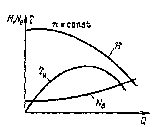
In (Fig. 1) the above is shown graphically.
Efficiency
The efficiency of a centrifugal pump motor is the ratio of useful power to consumed power. It is denoted by the letter η (this). Schematically, all this is shown in (Fig. 2)
η=(Р2/Р1)*100
Engine efficiency will never be more than one (100%) under any circumstances, because " perpetual motion machine» has not yet been invented, and all existing drives have losses. The power consumption P1 of the motor is greater by the amount of electric motor mechanical and thermal losses P vdv. (Fig. 2).
The efficiency of the pump, as mentioned above, is the ratio of hydraulic power to the input power on the pump shaft, and their difference indicates the power loss in the pump.
η=(Р4/Р3)*100
Power losses in a centrifugal pump also consist of several components, namely: hydraulic, mechanical and volumetric losses P vset. (Fig. 2). The overall efficiency of pumps is the product of the efficiency coefficients of volumetric, hydraulic and mechanical. The pump efficiency characterizes the degree of its constructive perfection, both mechanically and hydraulically.
Loss of hydraulic power in the pump consist of losses to overcome resistance (friction) in the impeller and housing during the movement of fluid from the suction pipe to the discharge pipe and vortex losses. Losses to overcome frictional resistance depend very strongly on design features pumps, the dimensions of their flow path, the quality of processing (roughness) of the walls and surfaces of the pump. These losses are proportional to the square of the fluid flow velocity. The eddy losses that occur in a pump depend on many factors. Very large eddy losses appear with a sudden expansion of the cross section or a sharp turn in the fluid flow. There are eddy losses due to flow separation from the surface of the impeller or when the pump operates outside the limit of its operating characteristic. The hydraulic efficiency of the pumps is within η g = 0.85…0.96.
η g \u003d H / (H + h)
Where:
H- pressure generated by the pump;
h– head loss inside the pump
Mechanical losses due to friction occurring in the supports of radial and axial bearings, in a mechanical mechanical seal, as well as friction losses on the working fluid that occur during the rotation of the impeller and pump shaft. Mechanical losses are also very dependent on the design, workmanship and size of the pump. The mechanical efficiency of the pumps is within η m = 0.95…0.98.
η m \u003d (P-P tr) / P
Where:
R- power, on the pump shaft;
R tr– power losses to overcome frictional resistance.
Volume loss mainly arise due to the flow of fluid from an area of high pressure to an area low pressure, through the gaps between the impeller and the diffuser or fixed parts of the pump housing. For example, in a centrifugal pump, part of the fluid from the volute, bypassing the impeller, flows back into the suction pipe, while it will not enter the pressure pipe, although energy has already been expended on it. efficiency η o for modern centrifugal pumps is from 0.96 to 0.98.
η o \u003d Q / Q to
Where:
Q- pump supply;
Q to- the flow rate of fluid passing through the pump impeller.
Work η g * η m * η o \u003d η and determines the overall efficiency of the pump. Changing the value of any of the factors leads to a change in the value and overall efficiency of the pump. This dependence is given by a function of the flow in the pump characteristic, and is depicted on the graphs as a curve η=f(Q). Useful pump power R(kW) can also be defined as the product of the weight feed ( Q) to the pressure ( H) according to the formula:
P=(pg*Q*H)/1000
Where:
pg – specific gravity liquids (N / m 3);
Q- volumetric flow of the pump (m / s);
H- pump head in (m).
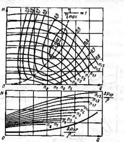
On (Fig. 3) are the performance characteristics of the pump series, as well as the dependence of the MPSH characteristic and the efficiency characteristic on the flow.
Theoretical basis operation of centrifugal pumps
Scheme of the device and the principle of operation of a centrifugal pump.
Basic equation of a centrifugal pump.
Dependences of the main parameters of the pump.
Cavitation and methods of dealing with it.
Operating characteristic and mode of operation of a centrifugal pump.
Operation of centrifugal pumps in one pipeline.
Axial pressure in a centrifugal pump.
The creation of pressure in a centrifugal pump occurs due to the kinetic energy acquired by the liquid in the channels of the impeller when the rotor rotates at a certain frequency, and the transformation of the resulting kinetic energy into pressure energy in the casing vane.
Figure 1.18
Scheme of a single-stage
centrifugal pump
The pressure is theoretically determined by the rotational speed and the diameter of the impeller (Fig. 1.19).
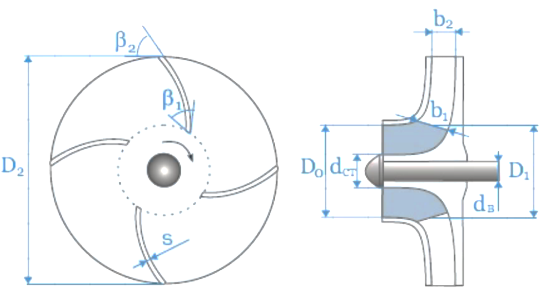
Figure 1.19 Parameters of the impeller of a centrifugal pump
When moving inside the channel of the impeller, a liquid particle has a relative velocity with respect to the impeller ω, which is directed tangent to the blade at the point of its application. But due to the rotation of the wheel at the number of revolutions P the fluid particle also acquires a circumferential velocity directed tangentially to the circle of radius r, defined as the product of the angular velocity and the radius r is the distance of the considered particle from the center of rotation, i.e.:
u = ω r = (1.17)
Consequently, a liquid particle leaving the impeller will have a circumferential velocity tangential to the outer diameter of the impeller at the exit point and a relative velocity directed tangentially to the trailing edge of the blade. As a result of the geometric addition of these velocities (u and w), a liquid particle will have an absolute velocity c along their resultant (along the diagonal of a parallelogram built on the directions of velocities u and w), in the direction of which elementary fluid streams will exit the impeller (Fig. 1.20 ).

Figure 1.20 Fluid movement in the channels of the impeller
For the entry and exit speeds of the wheel, the designations are the same, only the input speeds are given index 1, and the output speeds - index 2. Then we will have:
1) at the entrance to the shoulder blades
W 1 - relative speed,
C 1 - absolute speed,
U 1 - circumferential speed;
2) when leaving the shoulder blades
W 2 - relative speed,
C 2 - absolute speed,
U 2 - circumferential speed.
Euler's basic equation for determining the theoretical pressure of a turbomachine wheel, written in the very general view and valid for all bladed machines, i.e. water steam and gas turbines, centrifugal pumps and fans, as well as turbochargers:
H t = ![]() (1.18)
(1.18)
As a result of hydraulic resistance to the flow of fluid through the impeller, which requires some energy to overcome, the actual pressure generated by the pump is less than the theoretical one. Entering into equation (1.18) the hydraulic efficiency , taking into account the decrease in the theoretical head, we obtain the value of the actual head:
H q = · ![]() (1.19)
(1.19)
In centrifugal pumps with an axial inlet to the impeller α 1 = 90 °, and the second term on the right side of equality (1.19) will turn into zero and the Euler equation will take the following form:
H d = ![]() (1.20)
(1.20)
At the same time, the pressure is affected by the design of the impeller, in particular the width of the channels between the blades, which leads to a decrease in the actual pressure compared to the theoretical one (by 15-20%), due to the uneven distribution of velocities in the channels of the impeller. So, when the wheel rotates, the liquid filling its channels rotates in the direction opposite to the rotation of the wheel. This phenomenon can be represented by considering the movement of fluid in a closed volume between the blades, i.e., with the inner and outer outlet annular sections of the channel closed. On fig. 1.21 (channel I) shows a jet flow corresponding to an infinitely large number of elementarily thin blades. If the liquid has no viscosity, then when a closed vessel rotates around some axis rigidly attached to it, it will rotate relative to the walls of this vessel in reverse side with the same angular velocity as the vessel rotates around its axis.
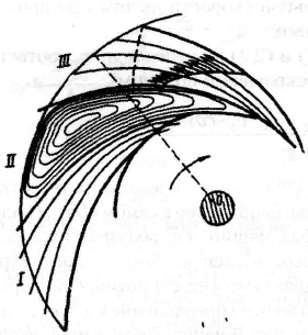 This phenomenon is called a relative vortex, and it will manifest itself the weaker, the more viscous the liquid and the narrower the channels. This vortex, adding up with the fluid flow from the wheel axis to the periphery, causes an uneven distribution in the wheel channels (see Figure 1.21, channel II).
In addition, the blades of a rotating wheel, when transferring mechanical energy to the liquid filling its channels, exert pressure on it, which is transmitted by the surface of the blade facing the direction of rotation of the wheel (convex side), as a result of which the pressure on the convex side is greater than on the opposite (concave side). ) side of the same shoulder blade.
Therefore, for practical use, expression (1.20) can be transformed and presented in the following form:H D = K (1.21)
where D 2 is the outer diameter of the impeller in m;
n is the speed of the pump shaft in rpm.
K is a coefficient depending on the angles a 2 , β 2 and the coefficient k, taking into account the finite number of blades.
The theoretical flow of a centrifugal pump can be represented by the formula:
where λ is a coefficient taking into account the areas occupied by the ends of the blades (is in the range of 0.92 ... 0.95);
ψ - coefficient depending on the change in angles α 2 and β 2 (ψ= 0.09...0.13);
2 - width of the wheel on the outer diameter.
The actual feed Q d is slightly less than Q t:
Q d \u003d η 0 Q T (1.23)
where η 0 is the leakage coefficient or volumetric efficiency, taking into account slotted fluid losses through the gap between the wheel and the housing.
The power consumed by a vane pump includes power losses in the pump and depends, in particular, on the pump efficiency η:
N pr = (1.24)
Power losses in a vane pump are made up of mechanical losses, disk friction losses, volumetric and hydraulic losses.
Thus, the efficiency of a vane pump is equal to the product four efficiencies corresponding to the specified losses:
![]() (1.25)
(1.25)
Power losses due to disk friction occur as a result of the interaction of the fluid flow with the outer surfaces of the impeller disks, as well as the unloading heel. The disk efficiency of vane pumps varies within = 0.85...0.95. The maximum efficiency reaches 0.89 for the most powerful oil mainline centrifugal pumps.
It is often necessary to test the pump at a speed different from normal. Therefore, it is necessary to know how the flow, pressure and power will change with a change in the number of revolutions. From the consideration of formulas (1.21, 1.22 and 1.24) it can be seen that if you change the number of revolutions n of the pump shaft, which corresponded to the pressure, flow Q and power N, then new pressure N "D, flow Q" and power N "proportional to n 1 .
![]() (1.26)
(1.26)
those. the pressure generated by the pump is proportional to the square of the number of revolutions,
![]() (1.27)
(1.27)
those. pump flow is proportional to the speed,
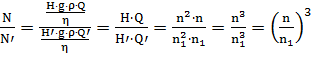 (1.28)
those. under the condition = const, hydraulic power is proportional to the cube of the number of revolutions,
The obtained dependences are called the law of proportionality or similarity and they are widely used to determine the parameters of the pump when the speed changes.
Malfunctions in centrifugal pumps occur as a result of not observing the conditions for the liquid to enter the pump. If in some areas of the pump the pressure drops to the saturated vapor pressure, then in these areas the liquid will begin to boil with the formation of air pockets in the channel that disrupt the smoothness of the flow. These pockets are filled in pairs. Vapor bubbles are carried away by the moving stream and, falling into the sphere of more high pressure, are condensed. The condensation process is very intensive. Liquid particles, trying to fill the region of the condensing bubble, move towards its center with a very high speeds. At the end of the condensation process, the liquid particles suddenly stop, as a result of which the kinetic energy of these particles is converted into pressure energy, and the local increase in pressure reaches a significant value (tens of megapascals).
The described process is accompanied by local hydraulic shocks, repeated tens of thousands of times per second. This phenomenon is called cavitation, which can occur in both the stationary and moving parts of the pump.
Cavitation is accompanied by strong noise, crackling, vibration of the pump, causes the destruction of the metal, lowers the pressure, performance and efficiency of the pump. In addition to the mechanical destruction of the metal, cavitation causes its corrosion. Cast iron breaks down especially fast. More resistant metals are also destroyed - bronze, stainless steel. Therefore, cavitation must not be allowed in the operation of the pump, and the suction height must be such that cavitation cannot occur.
When operating centrifugal pumps, cavitation can occur when the liquid level in the suction tank drops below the calculated level, the temperature of the pumped liquid rises, and the pump is improperly installed and mounted. In order to reduce losses in the suction pipeline, reduce, if possible, its length, make it more straight, install minimal amount reinforcement, avoid air pockets.
Centrifugal pumps have, in comparison with piston (plunger) pumps, a soft characteristic, i.e. flow depends on the pressure in the line. This dependence is reflected in the operating characteristic of the pump.
| Figure 1.22 Pump Performance |
To determine the operating mode of the pump during its operation on a specific pipeline, it is necessary to build the operating characteristic of the network. Network performance - this is a graph showing the dependence of the pressure in the network on the flow in the network. This graph is built according to the mathematical formula of the form:
H \u003d H st + kQ 2, (1.29)
where H st - static head;
kQ 2 - specific energy, which allows the fluid to move through the network by overcoming hydraulic resistance.
Static head expresses specific energy, due to which the liquid is supported in the network, but does not move through it. The second term expresses the specific energy that would allow the fluid to move through the network by overcoming hydraulic resistance. Using the network performance curve, you can select a specific pump design or predict the pump's operating parameters. The intersection point of the graphs of the characteristics of the network and the pump is called the operating point, its coordinates correspond to the working flow and the working pressure of the pump (Fig. 1.24).

Illustration 1.24 Determining pump operating parameters
Joint operation of centrifugal pumps in one line is widely used. To do this, the pumps can be connected in parallel - to increase the flow, or in series - to increase the pressure. The latter method is widely used in the creation of multistage centrifugal pumps that develop high pressure.
The sequential operation of the pumps is used when it is necessary to increase the pressure of the liquid supplied to the discharge pipeline. In this case, the first pump (Fig. 1.25, a) supplies fluid to the intake of the second pump. The second pump pumps it into the pipeline. Thus, the same amount of liquid passes through both pumps, which is supplied to the discharge pipeline with a head equal to the sum of the heads of these pumps (Fig. 1.25, b). When the pumps are operated in series, the flow of the first pump must be equal to the flow of the second or somewhat greater (within the working area of the second pump), and the pressure at the beginning of the discharge pipeline must be acceptable for the second pump in terms of maintaining its strength.
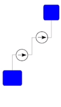
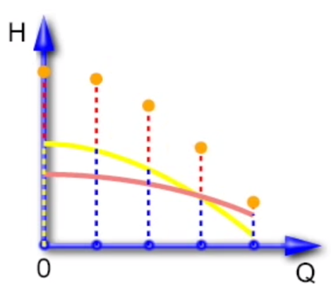

Figure 1.25 Serial connection of pumps
Most often, pumps operate in parallel ( pumping stations water lifting, oil pumping, water injection into the reservoir). Such pumps are usually installed in one pump room. They may have different characteristics. Let us consider a simplified case of the operation of two pumps, close to practical problems, when the resistance of the suction part of the system and pressure pipelines up to the nodal point can be neglected. With parallel operation of the pumps, their supply is added, and the pressures are equal. To obtain their total characteristics, it is necessary to add the abscissas of the characteristics of both pumps with equal ordinates (heads) (Fig. 1.26).

Illustration 1.26 Parallel connection of pumps
With parallel operation of two pumps, their operation mode is possible, in which the pressure of one of them will exceed the pressure of the other in its zero flow mode. Then one pump will force the liquid through the other in the direction of its reception. Such operation is possible, for example, with an increase in pressure in the discharge pipeline and in the case of starting one of the pumps with an open valve at its outlet and with the second pump running. Therefore, for parallel operation, it is necessary to select pumps so that the operating pressure does not exceed the pressure at zero flow of one of the pumps. It is recommended to select pumps for parallel operation with as close heads as possible at zero flow. To prevent the pumping of fluid by one pump through the others, it is necessary to install check valves at the pump outlets.
During operation of the pump, an axial force acts on the impeller - the result of the fluid flow acting on the inner and outer surfaces of this wheel. The axial force can be significant and emergency cause displacement of the impeller, heating of the bearings, and when the rotor is displaced, contact of the impeller with the fixed parts of the housing, resulting in abrasion of the walls of the impeller and breakdown of the pump.
To balance the axial force in single-stage pumps, the following are used:
Impellers with double entry;
Mutually opposite arrangement of impellers;
Holes in the impeller and sealing on it from the discharge side;
An unloading chamber communicating with the suction area using a tube or through holes in the rear disk; the lack of a chamber - a decrease in the efficiency of the pump by 4 - 6%;
Radial ribs that reduce the effect of axial force by reducing fluid pressure on the rear disc;
Thrust bearings.
To balance the axial force in multistage pumps, use:
Impellers with an appropriate fluid supply system from impeller to impeller;
Impellers with discs of different diameters (increase the diameter of the front disc or reduce the diameter of the rear disc);
An automatic hydraulic heel (Fig. 1.27) installed behind the last stage of the pump.
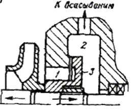
Figure 1.27 Scheme of the hydro-heel assembly:
1- chamber with discharge pressure; 2 - unloading chamber; 3 – hydraulic pad disc
Questions for self-control:
1. How is pressure created in the pump?
2. How does the number of blades in the impeller affect the head?
3. What elements does the impeller consist of?
4. What is the speed triangle?
5. The essence of the phenomenon called "relative vortex".
6. What determines the flow of centrifugal pumps?
7. In what coordinates is the operating characteristic of the pump built?
8. How is it determined work zone pump?
9. How is the cavitation phenomenon eliminated?
10. Why is the pump started with the discharge valve closed?
11. Why use parallel and series connection of pumps?
12. Causes of axial pressure and ways to balance it.
Page 1
The performance of a centrifugal pump can be calculated from equation (1.3) as the product of the free area and the absolute speed. In this case, it must be remembered that the live section is interpreted as the projection of the section onto a plane normal to the direction of velocity. To calculate the performance of centrifugal pumps, such a representation is inconvenient, therefore, the product of the flow cross section and the velocity projection onto the direction normal to the cross section is used, which is identical to it.
The performance of the centrifugal pump 9 in absolute value should be about 0 08 FK (where FK is the cooling surface of the condenser), and its pressure should be about 15 - 20 m of water. Art. The suction port of the pump must be connected to a clean tank compartment.
The performance of a centrifugal pump depends on the relative velocity of the liquid flowing through the channels of the impeller and the width of the impeller.
The performance of centrifugal pumps is much greater than that of other types of pumps.
The performance of centrifugal pumps at a constant speed is regulated by changing the opening of the pressure valve. Before starting the pump, close the pressure valve, open the air cocks on the pump housing and fill it, opening the valve on the suction line. After filling the pump, close the air cocks and turn on the electric motor for 3 minutes. As soon as the number of revolutions of the electric motor becomes normal, and the pressure on the pressure gauge corresponds to idling pump, gradually open the pressure valve and bring its performance to a predetermined value.
The performance of a centrifugal pump is determined by the characteristic, usually given by the manufacturer.
The performance of a centrifugal pump is regulated by changing the pressure under which it operates by closing the valve on the discharge pipeline. To stop the pump, close the valve of the discharge pipeline and turn off the electric motor. Then slightly tighten the pump seals if there is some leakage of water or brine. IN winter time drain water from the water pipes and the water pump if there is a risk of water freezing in them.
The performance of a centrifugal pump is proportional to the number of revolutions of the pump shaft, which is usually 1500 - 3000 per minute.
| Steam jacketed tank. |
The performance of centrifugal pumps is determined hydraulic calculation based on the conditions of joint operation of the pump and the pipeline system.
Power - work per unit of time - in relation to pumps can be determined by several ratios, depending on the accepted units of measurement for flow, pressure or head. Net power is the power supplied by the pump of the supplied liquid. If the supply Q is expressed in m 3 / s, and the pump pressure is in Pa, then the net power Np, kW, will be
With a mass flow Q M expressed in kg / s,
If the pump head is expressed in meters of the pumped liquid column, then
For water at a temperature of 20 ° C and q \u003d 9.81 m / s 2
If the water supply is expressed in m 3 / h, and the pressure is in m of water. Art., then
If the power must be expressed in l. s, then it is calculated according to the following formula:
Pump power, i.e. the power consumed by the pump,
where η is the efficiency of the pump.
From formula (2.46) it can be seen that the pump efficiency is the ratio of useful power to pump power
The efficiency of the pump takes into account the hydraulic, volumetric and mechanical losses that occur during the transfer of energy of the pumped liquid. Hydraulic losses are called energy losses to overcome hydraulic resistance when the fluid moves from the inlet to the pump to the outlet, i.e. in the suction apparatus, impeller and discharge pipe. Hydraulic losses estimate hydraulic efficiency pump:
where Nn is the useful power of the pump; Ng is the power expended to overcome the hydraulic resistance in the pump.
Volume loss occur due to the flow of part of the liquid from the high pressure area to the low pressure area (into the suction part of the pump) and due to fluid leakage through the seals. Volumetric losses are estimated by the volumetric efficiency of the pump
where N is the power lost as a result of fluid overflow and leaks.
where N m is the power expended to overcome mechanical losses.
Mechanical losses are made up of friction losses in bearings, seals and impeller relief disks, as well as friction losses outer surface impeller against liquid. Mechanical losses are estimated by the mechanical efficiency of the pump.
The efficiency of the pump is equal to the product of the hydraulic, volumetric and mechanical efficiency
and characterizes the perfection of the design, as well as the quality of the manufacture of the pump. The efficiency of large pumps reaches 0.92, and the efficiency of small pumps - up to 0.6 - 0.7 or less. The power of the motor driving the pump is always greater than the power of the pump. If the pump shaft is connected to the motor shaft with a coupling, then the installed power of the motor is determined by the formula
where kdv is the engine power safety factor.
Depending on the engine power N, kW, and the conditions of its operation, the following power reserve factors should be taken:
| N<2 | 1,5 |
2| 1,5—1,25
|
|
5| 1,25—1,15
|
|
50| 1,15—1,05
|
|
| N>100 | 1,05 |
If the pump shaft is connected to the motor shaft by a gearbox or belt drive, then the motor power is determined by the expression
where η dv is the efficiency of the drive (or gearbox).
The efficiency of the pumping unit, i.e., the pump connected to the engine, is equal to
where N a is the power of the pumping unit; η dv - engine efficiency.


