CADvent program - new opportunities for designing ventilation systems
Elena Berdinsky (CAD Specialist, Lindab LLC)
The CADvent program is a development of the Swedish concern Lindab and has been one of the leading programs for the design of HVAC systems in Scandinavia, Western and Eastern Europe for more than 15 years.
Since 1965, Lindab's Ventilation business has been based on the development of system solutions for ventilation and air conditioning. Having vast experience in working with ventilation systems and working closely with engineers and installers, the company's specialists realized the need to create a program that would help to quickly and efficiently design ventilation systems, include aerodynamic and acoustic calculations, allow you to create specifications for equipment and materials, and have communication with a cost estimate program.
In 1992, the first release of the CADvent program was released, which quickly won the trust of consumers. CADvent combines powerful calculation functions with handy tools for drawing and designing ventilation systems. The program is constantly being improved in accordance with the requirements of the time and taking into account the needs of designers.
On Russian market Lindab presents a set of programs for the calculation and design of ventilation, heating, plumbing and drainage systems, an indoor climate simulation program. These are CADvent, DIMcomfort, DIMsilencer and TEKNOsim programs.
CADvent modules
The CADvent software is the basic HVAC design tool and comes in three main packages:
- CADvent Secure - design of ventilation systems. Closed databases of Lindab products;
- CADvent Link - design of ventilation systems. Open databases - in addition to the full list of Lindab products, which is in the program, you can upload databases from other manufacturers;
- CADvent Plus - design and calculation of ventilation and heating systems, drawing of water supply, sewerage, drainage and deluge systems. Open databases.
Depending on the design tasks, the designer can choose one or another package, and later, if necessary, upgrade to a version with more functionality.

Design and Calculation Functions
The CADvent program is an object-oriented application for AutoCAD and allows you to quickly and efficiently solve the whole range of tasks that arise in the implementation of projects for ventilation systems - this is the selection of equipment, the execution of working drawings, all necessary system calculations, the creation of equipment and materials specifications.

The main functions of the CADvent program are:
- work on the AutoCAD 2004-2011 platform;
- 2D/3D design;
- automatic selection of sections of air ducts and pipelines;
- aerodynamic calculation / calculation of pressure losses in the system;
- automatic balancing of systems with the arrangement of throttle valves;
- noise calculation (acoustic calculation);
- associative labeling of system elements;
- quick changes to the system;
- automatic creation of plans/sections;
- automatic compilation of specifications of materials and equipment;
- the possibility of quick and easy replenishment of equipment bases;
- converting AutoCAD blocks into smart CADvent objects (data on dimensions, flow, dP, etc. are added);
- intelligent movement of elements with the function of maintaining system integrity using standard AutoCAD movement handles or a special CADvent function;
- automatic layer management;
- collision control;
- the ability to create non-standard elements;
- links to costing programs.
Working with equipment
The design of a ventilation system in CADvent is object-oriented, that is, the designer initially works with the equipment and system elements that he has. Each element included in the catalog is an intelligent object - a copy of a real-life equipment - and contains not only geometry data, but also the relationship between flow, pressure and speed, noise characteristics.
Databases of equipment and materials include thousands of items. In addition to the catalogs available in the program, the designer can independently create bases of air distributors and elements of ventilation systems or connect catalogs of air distributors from third-party manufacturers.
Intersection control
The collision control function helps the designer avoid costly design errors at all stages of the project and when coordinating the project with subcontractors.
Collision control allows you to control intersections between elements of a 3D model - elements of ventilation systems, intersections of air ducts and building envelopes created in AutoCAD Architecture (walls, windows, doors, floors, roofs, etc.), intersections with existing drawing with solids, intersections between all engineering systems of the building (ventilation, heating, plumbing, sewage and fire pipelines), as well as with AutoCAD MEP objects.
Interaction with AutoCAD
The program runs on AutoCAD 2004-2011, AutoCAD MEP (Autodesk Building Systems) 2007-2011, AutoCAD Architecture (Autodesk Architectural Desktop) specified versions, and AutoCAD Mechanical. The system requirements for installing CADvent are necessary and sufficient to install basic AutoCAD.
Standard AutoCAD editing functions - move, copy - are available for CADvent objects and do not affect their intelligence.
Interaction with the AutoCAD MEP program is implemented in a special program module available for all available configurations and allows you to import / export air ducts from the AutoCAD MEP program to CADvent for finalization, subsequent calculation and balancing of the system, drawing up specifications. When imported, AutoCAD MEP objects are automatically converted to CADvent objects, the objects have "handles" for moving, stretching, shrinking, etc.
Duct systems made in CADvent can be transferred to AutoCAD MEP in the same way, if necessary, modify, create cuts, specifications, etc.
Creation of working drawings
With the CADvent program you can create:
- plans on the mark;
- arbitrary sections;
- incisions.
A tinted isometric image of ventilation systems obtained using standard AutoCAD can be an excellent addition to working drawings and sometimes completely satisfies the customer.
An isometric view designer can easily build axonometry, create the necessary fragments and views.
The labeling of elements in the CADvent program is performed using labeling templates or text labels, which borrow the necessary data from the calculated model. Information is added to the drawing either at once for all objects of the same type with one click in accordance with the labeling settings, or in stages - element by element, at the request of the designer. The labeling is associative - when the characteristics of an element change (such as dimensions, cross section, air flow, pressure loss), the text label in the drawing is updated automatically, so there is no need to relabel the elements. The associativity of text labels not only saves the designer time, but also prevents incorrect information from appearing on the drawing.
Creation of working documentation
The CADvent program allows you to automatically create bills of materials and equipment, system calculation sheets almost with the click of a single button. The principle of drawing up a specification based on an existing 3D model is simple - everything that is on the drawing is automatically entered into the specification. At the same time, the possibility of data loss is minimized, the possibility of forgetting any element or miscalculating when determining the length of an air duct or pipeline is eliminated.
At the same time, the designer always has the opportunity to create a specification for a part of the ventilation system - for example, for a floor plan or a specific system, a specification for selected elements. All spreadsheet documents can be transferred to MS Excel or saved as PDF.
Visualization
If you need to create presentation views of systems at any stage of design for a visual presentation of the project to the customer or potential customers, you can use the visualization function built into the program.
The program makes it possible to create a perspective view of systems with the task of elevation, point and direction of view. The perspective view can also be supplemented with the necessary inscription and clarifying notes.
Additional utility programs
In addition to the CADvent functionality, the designer can use special programs that allow simulating the indoor climate (TEKNOsim), selecting diffusers taking into account the requirements for air velocity in the working area and noise (DIMcomfort), selecting and arranging silencers (DIMsilencer).


DIMsilencer program
DIMsilencer allows you to match round, rectangular and corner silencers. There are several silencer options available:
- according to the required sound power Lwa dB(A) after the silencer;
- according to the required noise level by frequency (Hz) after the silencer;
- for noise reduction;
- by its own noise generation.
As a result of the calculation, the user sees all parameters: noise before the silencer, noise generation by the silencer itself, noise reduction, noise after the silencer, noise by octaves, and also specifications selected muffler.
DIMcomfort program
DIMcomfort allows you to select air-distributing devices - diffusers, grilles, taking into account the air speed in the working area and noise. After specifying the type and geometry of the room, the amount of air (or the frequency of air exchange) and the temperature of the supplied air, the program automatically generates a three-dimensional model of the room. Selected air distributors are placed in the room. The designer can track how the required noise level in the room is maintained, the air speed in the working area, how the air flow from the air diffusers is distributed, and how the position of the air diffuser affects all these parameters.
The selected air terminals can be exported to the CADvent software with data on flow, pressure loss and noise saved.
The DIMcomfort and DIMsilencer programs are shareware and can be used independently of the CADvent program, in a separate installation, or in conjunction with CADvent. The programs are integrated into the CADvent interface, which allows you to instantly and losslessly carry out the necessary data exchange.
Detailed information on the CADvent program can be obtained on the website of the Russian representative office of the Lindab concern www.lindab.ru or by contacting the CADvent technical support service.
To create healthy and comfortable microclimatic conditions in the room, high-quality air exchange is necessary. Exhaust air saturated with carbon dioxide, excess moisture, dust and various contaminants must be removed in a timely manner, and fresh air masses must take its place. oxygenated. Such circulation is dictated by common sense and regulated by construction and sanitary and epidemiological standards.
As you know, planning in the house of any engineering networks begins with the preparation of project documentation and calculations. Competent allows you to create in each room of the building the microclimate necessary for normal human life.
Norms and rules used in the design of engineering networks
is the creation of a technically and economically justified layout of ventilation ducts and a competent selection of equipment that will ensure the microclimate standards regulated by 2.09.04-87. In addition, a competent project provides for 100% operability and maintainability of the system, as well as satisfaction of all architectural and technical requirements.Must comply with strictly defined sanitary norms and state standards.
When designing ventilation, SNiP 2.04.05-91 is the main document that any designer is guided by.
In addition to this set of rules, the following regulatory documents may also become necessary:
- SNiP 2.01.02-85;
- SNiP II-12-77;
- GOST 12.1.005-88;
- SNiP 2.08.01-89;
- SNiP 2.08.02-89;
- SNiP 2.09.04-87;
- SNiP 2.09.02-85;
- SNiP 2.01.01-82.
Project development stages

At the first stage of the development of the ventilation system project, the customer meets the designer, where the terms of reference are drawn up and the initial data necessary for correct calculations are determined.
The second stage is the provision to the customer of technically and economically justified schemes of ventilation systems, with options for the equipment used for this. From the options presented, the customer chooses the best one and makes comments, after which he submits it for approval to the appropriate authorities. Only after the comments from the regulatory authorities have been eliminated, the project proceeds to the third phase - the preparation of complete technical documentation with specifications necessary materials and equipment, as well as an estimate of the work.
The project can be created "the old fashioned way", on a drawing board, but, as a rule, modern companies involved in design work use software for this.
Programs for the design of ventilation systems
Today, there is a mass of software that serves to significantly speed up the process of performing calculations, drawing up duct layouts, filling out specifications and drawing up drawings. Despite the apparent simplicity, the designer must have the appropriate knowledge, experience in dealing with software, etc. Let's consider several common programs that help ventilation system designers in compiling project documentation.
Autocad
The program is designed to create the most accurate drawings, diagrams and other design documentation in two-dimensional or three-dimensional display. AutoCAD has two types of interface:

When designing ventilation in autocad, the designer will have access to: a full set of functionality for drawing up and checking drawings, the ability to scale, and the use of panoramic functions. In addition, it is possible to use and bind objects from third-party libraries, import-export tables and text files, layers, publish 3D drawings and much more.
Today, AutoCad is the software that is most common in architectural design and design offices, since it is this utility that has the function of supporting teamwork on a project.
It should be understood that the AutoCad program is not just an electronic drawing board, it is a powerful software package that requires certain knowledge and experience to use.
- First of all, you need to make sure that your PC has system requirements, to work with this utility (above 2 GB RAM; 2 GB free disk space; high resolution monitor).
- After installing the software, familiarize yourself with the interface, which consists of a quick access panel (next to the red letter A in the upper left corner); ribbon, which, in turn, consists of several bookmarks; the status bar (at the bottom of the screen) and the command bar (above the status bar).
- To create a new document, select File - New.
Next, you can create a sketch, drawing, or complex object. Basic knowledge required to work in English because the interface language is English. In addition, you need to be at least an engineer and know the commands that will be needed to create drawings. To learn how to use this utility, you can use the reference book directly from the program menu.
AutoCad is a paid program with a free 30 day trial period. The cost of the latest licensed network version of AutoCad 2016, on the developer's website, is 5 thousand euros. There are special prices for local and network versions of the program for educational institutions.
magicad
This powerful utility is designed to perform calculations and three-dimensional design of engineering networks. The magicad ventilation design program includes several basic modules, among which is the Magicad-Ventilation block. 
As a graphical platform, the utility uses AutoCad or RevitMap. This software package allows you to:
- Creation of ventilation schemes with tracing both in manual and automatic mode.
- Arrangement of fittings and other equipment.
- Selection of sections of mines, channels and air ducts.
- Calculation of aerodynamic resistance of air ducts and equipment.
- Acoustic calculation.
- Balancing the ventilation system in automatic mode.
Magicad has the following features:
- Use of ventilation equipment base.
- Work with text designations of elements.
- Creation of specifications of materials and equipment;
- Control over intersecting elements in sketches and drawings.
- Work in 2D and 3D modes.
- Export data to other programs and much more.
A feature of this program is the presence of a database of ventilation equipment, which contains a huge number of products, with complete data on the pressure, air flow, dimensions, and geometry of the element, as well as its noise characteristics, etc. When drawing up a drawing, the program will automatically select shaped products, when connecting two air ducts - a tee or a cross, if the diameter of the air duct changes, the Magicad utility will immediately suggest the necessary adapter.
The Magicad program allows the designer to create projects of ventilation systems of any complexity in the shortest possible time.
The interface language is English and Russian. The cost of the full local licensed version is 4560 euros. The price of a full network license is 5700 euros. There are special offers for purchasing upgrades for 1, 2 and 3 years.
To successfully work with Magicad Ventilation, you need to be an engineer, be able to work with the AutoCad graphics platform. Official representatives of the developer often conduct online training on how to work in the program. The average cost of such training is from 10 to 16 thousand rubles. for the course.
Ventcalc
The program among designers is considered the most simple and functional. Indeed, to create a ventilation network diagram, it is enough to enter the required initial data and the program will provide a ready-made sketch with all the necessary data for further selection of equipment. 
Regardless of the chosen type of ventilation system, this utility copes equally well with the necessary calculations. The functionality of the program allows you to:
- Make a calculation of the cross section of the air outlets, taking into account all variables.
- Calculation of the resistance of mines and channels. Based on the calculations, the program automatically selects ventilation equipment.
- Calculation of the aerodynamic resistance of the network.
- Make a competent calculation of natural ventilation.
- Determine the optimal section of the ventilation shaft, which will ensure the predominance of thrust over the resistance of the air mixture at a certain flow rate.
- Make a calculation of the heating power of the heater.
Vent calc will perform as soon as possible necessary calculations which greatly simplifies the work of the designer. The advantage of this software is that since 2010 Vent calc has been distributed free of charge. The software interface language is multilingual.
Сadvent
The cadvent ventilation design software is a kind of add-on for drawing ventilation systems, created on the Avtocad graphics platform. This utility contains a complete set of tools for drawing diagrams, has powerful capabilities for conducting the necessary calculations, creating three-dimensional models, presentations, etc. 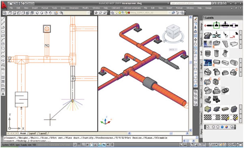
This software product allows you to:
- Calculate cross-sections and pressure losses in air ducts.
- Acoustic calculations.
- Create two-dimensional drawings with the necessary notation.
- Produce 3D modeling.
- Prepare specifications for the necessary elements of the system, with possible export to Excel.
- Create high quality 3D presentations.
The main feature of this software is the ability to create complete sets working documents, including calculations, specifications of materials, two - and three-dimensional drawings, individual sections and elements of the system.
To work in this software, you must be able to handle the avtocad graphics platform, be able to work with spreadsheets and libraries. The interface language is English. The cost of the software package depends on its configuration: ventilation module with the ability to manually update databases - 500 USD; ventilation module with automatic database update - 1500 USD; ventilation, heating, plumbing module with a complete base of elements from European manufacturers - 2500 USD
Despite the seeming simplicity of creating projects in the above software- this is a rather technically complex process that requires extensive knowledge, therefore, to create project documentation and calculations, contact only specialists.
When planning the design and renovation of the bathroom, one small but very important point should be taken into account - the problem of air exchange. good ventilation in the bathroom and toilet is necessary not only to ensure the flow of fresh air.
With the help of this system from the bathroom are removed unpleasant odors and excess moisture. If the ventilation system is planned and implemented correctly, bathroom owners will not have to worry about mold and mildew.
The absence of normal ventilation and the excess humidity caused by this circumstance will create almost luxurious conditions for the development of harmful flora.
The building guides clearly indicate the norms that must be followed for effective ventilation of sanitary rooms with high humidity.
The system must supply fresh air to the bathroom or toilet at a rate of 25 cu. m / h, and for a combined unit twice as high - 50 cubic meters. m/hour. These standards are minimum.
Depending on the characteristics of air exchange, natural and forced ventilation are distinguished. In the first case, air exchange occurs due to the difference in air pressure outside and inside the room.
Air streams penetrate through windows, doors, special ventilators, etc. It should be noted right away that due to the peculiarities of the bathroom design, the use of natural ventilation does not always allow you to get the desired effect.
For ductless ventilation in the bathroom, it is necessary to make an opening that will connect the house ventilation duct with the bathroom
With forced or artificial ventilation of the room, special fans are used that provide sufficient air exchange.
Most often, the fan helps to move air from the room to the street, while fresh air masses enter the bathroom from the living quarters.
Sometimes small fan put in the toilet, even with good natural ventilation, to speed up the purification of air from unpleasant odors.
If it is not possible to organize a sufficiently intensive air exchange in a natural way, forced ventilation is carried out without fail.
Depending on the purpose, there are:
- exhaust;
- supply;
- mixed ventilation.
The exhaust principle has already been described a little above: the air is removed through the ventilation duct, and the new one comes from outside. Supply ventilation is organized differently: air is forced in from the outside and forced out through the channel.
When using mixed ventilation, both the air supply and its removal are regulated.

A beautiful decorative grille for the hood in the bathroom will not only hide the design, but can also become a spectacular detail of a stylish interior.
Specialists also distinguish between channel and channelless ventilation, which is characterized by the presence or absence of a ventilation channel.
If possible, the creation of special channels should be avoided. Usually, an opening is made in the wall that opens into a common ventilation duct. high-rise building and install a fan in it.
In a separate bathroom, if there is only one room with access to the ventilation duct, another fan is installed in the wall opening between the bathroom and the toilet.
The installation of a separate ventilation duct makes sense in places that require intensive removal of polluted or moisture-saturated air.
Diagnosis of ventilation status
Before you start altering the ventilation in the toilet and bathroom, you should carefully examine its device and check the condition. To begin with, the draft is examined: a sheet of paper, a lit match or a lighter are brought to the vent.
If the paper sticks to the hole, or if the flame is clearly moving towards the ventilation duct, there is a draft. On a hot windless day, the thrust can be significantly less than in other periods.
The presence of draft in itself does not always indicate the normal state of the ventilation system.
It is imperative to check the condition of the ventilation duct, which may be partially cluttered after inept repair work or for some other reason.
By removing obstacles, you can significantly improve the quality of the ventilation system.

To check the draft in the bathroom, a sheet of paper or a lighter flame is brought to the vent. Checking should be done when open door, and then - with the closed
If in the latter case the draft has noticeably decreased, you should think about additional means of micro-ventilation.
Most often, it is enough to install special grilles in the doors of the bathroom and toilet to ensure the normal supply of fresh air to these rooms even when closed doors and windows.
What you need to know about fans
When buying a fan, be sure to evaluate the amount of noise that it produces. The indicator should not exceed 35 dB. In the bathroom, such equipment should completely update the composition of the air about 5-8 times within one hour.

Exhaust fans intended for use in bathrooms may have different design and design, in addition, they differ in power
According to the type of installation, domestic duct fans are distinguished, designed for installation directly in the ventilation duct, as well as radial models.
They are installed at the outlet of the ventilation duct. Usually channel models look unpresentable because they are hidden inside the channel, but radial devices are provided with a beautiful case so as not to spoil the overall impression of the environment.
The design of fans can also vary significantly:
- traditional axial models move air along the axis of the device using special blades and are designed for ductless systems;
- in low-performance diametrical models, a drum-type wheel is used;
- centrifugal devices with a volute casing are distinguished high performance and increased noise level during operation;
- small centrifugal-axial devices are less noisy, but work almost as efficiently as centrifugal models.
Taking into account the specifics of bathroom ventilation, fans are sometimes additionally equipped with timers that allow you to extend the operation of the device in the toilet or gyrostats to more effectively remove excess moisture from the bathroom.
Fans that are weak in power will not be able to provide normal ventilation of the room, however, you should not use too powerful models.
Strong centrifugal fan can cause such an intense air flow that the inflow will not come from outside, but from other ventilation openings, and the exhaust air will again be in the house.
Interesting information about installing an exhaust fan in the bathroom is presented in the following video:
Features of ventilation installation
If for some reason there is no ventilation in the bathroom, create necessary system it's not that hard.
Apartment buildings are usually designed in such a way that the ventilation duct is located directly behind the wall of the bathroom or toilet. It remains only to carefully make a hole in the right place (if there is none) so that it goes into this channel.
A radial axial fan is installed inside the opening. The device is connected to the power supply, observing all the requirements for the operation of electrical appliances in rooms with high humidity.
If necessary, mount additional controls (timer, gyroscope, etc.). The niche is closed with a beautiful decorative lattice.
If the apartment has a separate bathroom, and the ventilation duct is located outside the walls of both rooms, the second fan is installed in the same way as described above.
Otherwise, a vent is made in the wall separating the toilet and bathroom. A fan is also placed in this opening and closed decorative screens from two sides.
Sometimes it is more convenient to use decorative grilles, in which the design provides for mounting the fan in special sockets.
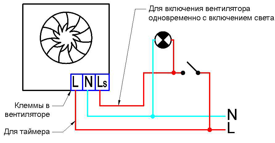
The figure clearly shows the connection diagram of the exhaust fan to the power supply using an timer, which allows you to turn off the fan some time after the visitor leaves the bathroom
It is somewhat more difficult to solve the problem of ventilating a bathroom when the ventilation duct borders on another room. In this case, you will have to create duct ventilation.
First you need to choose a location for the device air vent in the bathroom and toilet. Then it is necessary to draw up a plan for the placement of the ventilation duct, along which the air masses will move out.

When creating duct ventilation in the bathroom, a flexible corrugated box is used only in small areas where the installation of other structures is impossible or difficult
There are the following types of ventilation ducts:
- plastic round or rectangular section;
- hard or soft corrugated metal;
- metal, tin or galvanized, usually rectangular.
Plastic boxes are easier to install and lighter in weight than metal structures, while they are durable and easy to care for.
Therefore, plastic structures are confidently replacing metal from the construction market. Corrugated products are used extremely rarely, they are valid only for short distances and are used only in particularly difficult cases.
After the installation of the ventilation system is completed, it is necessary to check the operation of the equipment.

To create duct ventilation in the bathroom, metal or plastic boxes of rectangular or round cross section should be used.
Common mistakes when installing ventilation
It happens that the operation of a brand new ventilation system suddenly turns out to be unsatisfactory or is initially ineffective.
This may be due to one or more errors made during its installation. When figuring out how to properly ventilate the bathroom, you should immediately take into account these points.
Here are some of the most common mistakes:
- The ventilation duct is designed incorrectly, which makes it difficult for the movement of air masses.
- The tightness of the ventilation duct connections is broken.
- The fans are installed incorrectly and make too much noise.
- The channel passes through the living quarters in such a way that the ventilation noise interferes with the normal life of the family.
First you need to find out the cause of the problem, then fix it. A number of troubles can be avoided by paying attention to these points at the design stage of the ventilation system.
If this was not done, and problems appeared already during the operation of the structure, a serious alteration of the entire ventilation system may be required.
An alternative troubleshooting option is to use noise absorbers. different type to reduce unpleasant sound effects.
To improve the process of moving air masses, you may have to install a more powerful fan.
Sometimes excessive noise during fan operation indicates its incorrect installation, in which the so-called “alignment” was violated. In this case, it is enough to remove the device and install it again with strict adherence to the installation technology.
Usually, after this, the amount of noise from the operation of the fan is significantly reduced.
The supply type of ventilation in bathrooms is extremely rarely used, but if such a decision is nevertheless made, you should think about the temperature of the air entering from the outside.
IN winter time cold air flow can be extremely uncomfortable for bathroom visitors.
To solve this type of problem, the air entering the room is heated using special electrical appliances.

To ensure enough fresh air enters the bathroom, a beautiful grille is installed at the bottom of the door, which makes the room less airtight.
There are several common misconceptions that can negatively affect ventilation work. When designing and installing the system, remember that:
- an exhaust fan is not enough if a normal supply of fresh air is not provided to the room;
- big and bulky channel system ventilation is not always more effective than low-budget ventilation methods if they are chosen correctly;
- the presence of an air conditioner in the house, as well as a cleaner, ionizer, humidifier and others similar devices does not provide normal ventilation of the premises, since with their help fresh air does not enter the rooms.
Usually the design of the ventilation system for the bathroom is very simple, you can do it yourself.
But if some calculations or the implementation of a complex-shaped ventilation duct are required, and the novice master does not have experience in such work, it is better to consult professionals or completely entrust them with all the work.
The quality of ventilation cannot be neglected, since the health of the residents of the house depends on its condition.
.dwg format
Ventilation systems. working draft
Building №1
Supply and exhaust general exchange and local exhaust ventilation with mechanical stimulation is designed in the building.
Air exchange in the premises is determined for the assimilation of heat excess from:
Equipment
Solar radiation and local exhaust compensation.
In areas with air conditioning, outside air is supplied in the amount of the sanitary standard for the worker.
For supporting optimal parameters of internal air in the areas of adjustment, processing of parts on CNC machines, an air conditioning system based on split systems and steam humidification of the supply air during the cold period are provided.
indoor units wall and ceiling types and outdoor units installed on the facades are connected by freon pipelines made of copper pipes with thermal insulation made of foamed rubber.
Separate systems supply ventilation production building are provided for:
Section for processing parts on CNC machines
- setting sections of category B3.
The supply systems equipment is located in separate ventilation chambers. The bottom of the holes for receiving devices is located at a height of more than 1 m from the level of stability of the snow cover. Determined according to the data of hydrometeorological stations or calculation, but not lower than 2 m from the ground level.
Air exchange in the surface mounting area, cleanliness class 8 ISO, designed for:
-supply of sanitary standards of outdoor air for people;
Air exchanges in clean rooms should not be less than those required for the production of microelectronics in accordance with Table. B2 GOST R ISO 14644-4-2002:
For cleanliness class 8 ISO, at least 10 m3 of supplied air per 1 m2 of room area per hour.
Supply air is supplied by a separate system located in the ventilation chamber. The intake of outside air is carried out from the mark of 16.700m.
To maintain the required microclimate parameters, the supply air is heated and humidified during the cold period, cooled and dried during the warm period.
Supply air is processed in central air conditioners, consisting of:
-air filter class F6;
- water heater;
- class F9 air filter;
The coolant is ozone-safe freon supplied to the air cooler via copper pipes With effective thermal insulation type "K-FLEX".
The supply air is supplied to the clean rooms in the amount providing for:
Supply air from the central air conditioner enters the room through air distributors with H11 filters built into the ceiling.
Building №2
General exchange supply and exhaust ventilation is provided for the premises of complex workplaces. Ventilation equipment with a capacity of less than 5000 m3/h is installed in false ceiling corridor, the installation of the necessary fire dampers is provided. Outside air is supplied in the volume of the sanitary standard for the worker.
To maintain optimal parameters of indoor air in the areas, an air conditioning system based on split systems is provided.
The wall-mounted indoor units and the outdoor units installed on the facades are connected by freon pipes made of copper pipes with thermal insulation made of foamed rubber.
Of people
-equipment
-solar radiation
- supply air
Building №5
For the halls of climatic and dynamic tests, general exchange supply and exhaust ventilation is provided.
Air exchange in the premises is determined for the assimilation of heat emissions from:
Of people
-equipment
-solar radiation
Ventilation equipment is installed in the ventilation chamber. Supply air to the premises is supplied in working area, the exhaust is removed from the upper zone through wall grilles, equipped with built-in valves for regulating the air flow and direction of the air jet.
The bottom of the holes for receiving devices is located at a height of more than 1 m from the level of snow cover stability, determined according to the data of hydrometeorological stations or by calculation, but not lower than 2 m from the ground level.
The observation cabin is provided with split system air conditioning.
Building №9
Air exchange in areas of cleanliness class 8 ISO, designed for:
Assimilation of excess heat from technological equipment, people, solar radiation;
-compensation of local exhaust;
-supply of sanitary standards of outdoor air for people; Air exchanges in clean rooms should not be less than those required for the production of microelectronics in accordance with Table. B2 GOST R ISO 14644-4-2002: - for cleanliness class 8 ISO, at least 10 m3 of supplied air per 1 m2 of room area per hour. Supply air is supplied by a separate system located in the ventilation chamber. The intake of outside air is carried out from the mark of 16.700m. To maintain the required microclimate parameters, the supply air is heated and humidified during the cold period, cooled and dried during the warm period.
The supply air is processed in a central air conditioner, consisting of:
Receiving unit with air valve;
- air filter class F6;
- water heater;
- freon air cooler with a separator and a condensate collection tray;
- electric air heater of the second heating;
- fan block with reserve section;
- class F9 air filter;
-electric humidifier with built-in steam generator;
The cooling source is a condensing unit installed on the roof of the building.
The refrigerant is ozone-safe freon supplied to the air cooler through copper pipes with effective thermal insulation of the K-FLEX type.
The supply air is supplied to clean rooms in the volume providing for:
Compensation for local exhaust ventilation
- sanitary standard for workers
-compensation for air escaping through door gaps
- creating a pressure drop between the clean rooms and the corridor from 5 to 20 Pa.
The supply air from the central air conditioner enters the room through air distributors with H11 filters built into the false ceiling.
The hood is carried out from the lower zone through the wall grates.
To set and maintain a pressure difference between the premises and the corridor, air flow regulators are used on the supply and exhaust air ducts of ventilation systems. Excess air flows into the corridors through slots in doorways and adjustable grilles installed at the bottom of the rooms.
The control of pressure drops is carried out visually with the help of differential pressure gauges. Local exhaust ventilation systems are provided from process equipment emitting harmful substances.
For exhaust systems with harmful substances Hazard class 1 and 2 standby fans are provided.
Air ducts of local exhaust ventilation systems passing openly along clean rooms are made of polished stainless steel.
The air of the local exhaust ventilation system from the technological equipment of the sites is thrown out vertically upwards, at a height of 2 meters from the roof mark.
To ensure optimal parameters of indoor air during the warm season, the technological office and the back office are provided with air conditioning based on split systems. The wall-mounted indoor units and the outdoor units installed on the facades are connected by freon pipes made of copper pipes with thermal insulation made of foamed rubber.
Building №11
General exchange supply and exhaust ventilation is provided for laboratory premises. Outside air is supplied in the volume of sanitary norms per worker. To maintain optimal parameters of indoor air in the laboratories, an air conditioning system based on split systems is provided.
Ceiling-type indoor units and facade-mounted outdoor units are connected by freon pipes made of copper pipes with foamed rubber thermal insulation.
The cooling capacity of the systems is designed to assimilate heat surpluses from:
Of people
-equipment
-solar radiation
- supply air
Ventilation equipment is installed in ventilation chambers on the technical floor. The air of the local exhaust ventilation system from the technological equipment of the sites is thrown out vertically upwards, at a height of 2 meters from the roof mark.
The supply air to the premises is supplied to the working area, the exhaust air is removed from the upper area through wall grilles, equipped with built-in valves for regulating the air flow and direction of the air jet.
The supply air for each building is processed in the supply units, which are located in the ventilation chambers. Air handling units are configured:
Receiving block with air valve;
- EU4 class filter
- water heating heat exchanger
- supply fan
Supply air temperature control during the cold season is carried out by an automation system based on pump mixing. Automation is provided to regulate the parameters of indoor air, to protect heaters from freezing.
Connection of heat exchangers to the heat supply system is provided using two-way valves with installation circulation pumps. The necessary air and drain valves are provided on the piping of the heat exchangers, shut-off valves, measuring instruments.
Air ducts of ventilation systems are made of thin-sheet galvanized steel according to GOST 14918-80*.
Air exchanges in all rooms are given in the tables:
Data on local suctions in tables 1.
Air volumes by hazards in table 2.
Air volume by production premises in table 3.
Building number 6. Boiler room
General exchange supply and exhaust ventilation is provided in the GPU room.
Air exchange is determined for the assimilation of heat releases from:
Equipment
-solar radiation
Extraction is provided from the upper zone by two roof fans. The inflow is carried out through an air insulated valve with manual drive type GERMIK-P.
The bottom of the holes for the receiving device is located at a height of more than 1 m from the level of stability of the snow cover, determined according to the data of hydrometeorological stations or by calculation, but not lower than 2 m from the ground level.
Information about heat loads on ventilation
Building №1 119600W
Case №2 5000W
Case №5 94000W
Case #9 95400W
Case №11 56500W
Noise protection
Fan units of supply systems are installed in ventilation chambers on vibration-isolating bases in separate blocks with sound-absorbing insulation. Radial ventilation units are connected to air ducts through flexible connectors. In ventilation chambers and heating point foundationless low-noise pumps are installed for heat supply of heaters and heating.
The speed of movement of water in pipelines, air in air ducts and in air distributors does not exceed the recommended values in terms of acoustic indicators.


Protect a newly renovated bathroom from mold and high humidity Good ventilation in the bathroom will help. Proper ventilation in the bathroom prevents the formation of condensate from hot steam, which serves as an excellent medium for the spread of fungi. Over time, mold and mildew become increasingly difficult to remove from the surface of walls and furniture.
Ventilation in living quarters
In rooms with increased accumulation of humidity, natural or forced ventilation sometimes both are used at the same time for greater effect. Each of them has its own characteristic features.
Forced exhaust in the bathroom
Unlike natural ventilation, this option requires a more serious approach to installation. He successfully copes with the problem of eliminating condensate. Forced ventilation is chosen if the existing hood does not cope with its functions. It is easy to check its work, just bring it to ventilation duct burning match. If the flame from it oscillates from side to side or tends upward, then everything is in order. In any other case, you need to do a forced ventilation project.

It is better to lay forced ventilation at the design stage of the house. But if it is needed in an apartment, then ventilation ducts are already provided there.
Ventilation in the bathroom wooden house is needed not only to improve the climate in wet rooms, but also to protect walls from decay, because over time, logs can deteriorate and collapse when moisture accumulates.

Before you make ventilation in the bathroom, you need to choose exhaust fan. At the same time, attention should be paid to the following settings:
- Unit power
This indicator is selected depending on the area of \u200b\u200bthe room.
- Device noise level
When turned on, some fans are very noisy, ideally their sound level should not exceed 30 dB.
- Device type
Models of ventilating devices on ball bearings last longer.

There are three types of fans:
- With a timer.
They work for a certain amount of time, usually no more than half an hour.
- Combined models with a light switch.
As soon as a person enters the bathroom, the device immediately turns on, but sometimes the time spent by the visitor is not enough for the air to be completely cleared.
- independent models.
They are not tied to other electrical appliances in the bathroom or toilet, but work according to the established mode.
On a note: The fan in the ventilation in the bathroom must be installed away from electrical appliances, and the electrical wires leading to it must be insulated with high quality.
Installation of ventilation in the bathroom with a ventilating device is carried out in several stages:
- Choice suitable place for the fan. Such that he could distill as much of the air as possible through himself.
- Installation of the device on the exhaust shaft, on the roof.
- It is possible to install an extractor hood with a valve in the bathroom window.
- To improve the effect of the fan will help heated towel rails or radiators.
- A check valve must be installed in front of the fan, which would prevent the penetration of air from the outside.
- All air ducts and individual sections of pipes are connected using silicone sealant. Installation of ventilation in the bathroom begins with fixing the central channel, and then installing tees and bends in it.
- After fastening all additional channels, install a check valve on each of them to prevent air from moving from one room to another.
Natural ventilation in the bathroom and toilet
This option is cheaper than the previous one, it can be easily used for different types of housing. When it is installed, the movement of air masses occurs through specially made vertical channels. Such ventilation can be done in the bathroom with your own hands, it is effective even in wooden houses.

A window in the bathroom is another reason to think about natural ventilation.
Installation of natural exhaust in the bathroom begins with the basement. In the foundation of the house, special holes should be laid or windows for ventilation should be provided. Channels for the movement of air inside the building are laid directly in the walls of the building. Sometimes ventilation is carried out in the ceiling in the bathroom, and then goes to the attic.

Answer the question of how to make a hood in the bathroom in a private house and apartment will help the following tips:
- The air duct must run in a vertical plane.
- If you want to combine the hood for the bathroom and the toilet, then according to the project they should be close to each other. It is better if they are located on the same floor.
- The inside of the duct must be smooth so that nothing blocks the movement of air.
On a note: There are projects when the ventilation of a bathroom in a private house is combined with a kitchen, and from there it immediately goes out through a hole in the wall.
Bathroom ventilation connection diagrams
Among the varieties used today, four of the most popular are distinguished, differing from each other in the principle of action:
- Exhaust scheme
It is often used for an exhaust device in the bathroom through the toilet in apartment buildings. The operation of such a scheme is based on the removal of exhaust air through an outlet.
- Supply and exhaust option
Here, clean air is supplied through a door or window, and the same amount of exhaust air masses go through the vent directly into the ventilation shaft. When arranging such a hood in the bathroom with your own hands, you need to be prepared to prevent the occurrence of drafts in the room.
- Forced supply and exhaust scheme
This is an effective option for providing ventilation in the bathroom, with it you can adjust the rate and speed of exhaust air removal. After choosing this design, you can not worry about humidity and musty odors. The fan built into the circuit can always adjust the optimal microclimate of the room in time.
- Exhaust forced ventilation option
It is associated with a lot of noise, but it quickly removes unpleasant odors from the building. It is used when the question arises of how to make general ventilation for the bathroom and toilet. The effectiveness of this option is several times higher than that of a natural extract.

On a note: Newbie create proper ventilation in the bathroom without the participation of specialists will be difficult.
Photo gallery
Those who are thinking about how to properly and effectively extract the hood in the bathroom should consider the photos below. Surely one of these options will help you make the right choice.


