TO category:
Deep pumps
Automation schemes deep pumps
Starting and automatic shutdown of the pump in case of violation of its normal operation are carried out by magnetic starters or special magnetic stations.
Magnetic stations carry out both manual and automatic control of pump motors depending on the water level in the water collector or well.
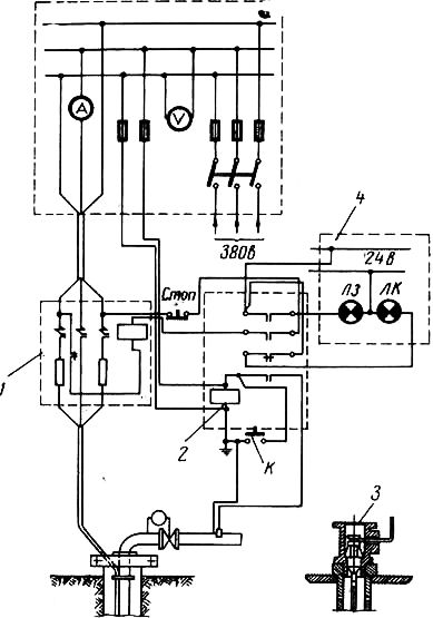
On fig. 89 shows a schematic diagram of a PET-type control system for deep-well pumps with electric motors up to 12 kw. Connection of the electric motor of the pump to a network is carried out by the automatic switch АВ. At the same time, the LZ lamp lights up, signaling the supply of voltage and that. that the pump is off.
By turning the handle of the universal switch UP in position P (manual control), the coil L of the magnetic starter is turned on, the power contacts of which turn on the pump, and auxiliary contacts switch the lamps. The LK lamp lights up - the pump is running and the L3 lamp goes out.
With automatic control of the pumping unit, the handle of the universal switch is set to position A (automatic control). Through the opening contact of the level switch RU, the magnetic starter L is activated, including the pump.
When water rises to the upper contacts of the KVU level sensor (Fig. 90), the RU relay is turned on, powered through the rectifier bridge and resistor 2 SD. The NC contact RU in the starter circuit L will open and the latter will turn off the pump. The contact block of the starter L will turn on the green lamp LZ - the pump is turned off.
When the water level in the tank drops below the contacts of the lower level of the KNU, the circuit of the level switch breaks, which, having lost power, will turn on the starter L and the pump again with its opening contact. The closing contact of the starter L will turn on the LK lamp - the pump is running. Then the cycle repeats.
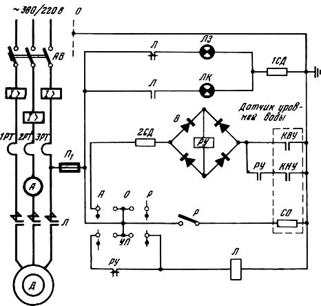
Rice. 89. circuit diagram control systems for downhole pumps with electric motors up to 12 kW
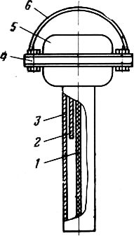
Rice. 90. Level gauge:
1 - low level contact; 2 - contact of the upper level; 3 - contact of the upper and lower levels; 4 - sensor terminal panel; 5 - casing 6 - suspension
To prevent icing of the contacts of the level sensor, a resistor CO (heating resistance) is used, which is turned on by the toggle switch P.
The control of the pump motor loading is carried out according to the readings of the ammeter A.
Protection of the electric motor against short circuits is carried out by electromagnetic releases of the AB machine.
Overload protection - thermal releases of the same machine.
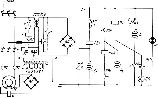
On fig. 91 shows a schematic diagram of control systems of the type (PET for deep-well pumps with electric motors up to 65 kw.
As well as when controlling pumps with a power of up to 12 kW, the electric motor is connected to the network by turning on the AB machine.
At the same time, lamp L3 lights up, signaling the supply of voltage and the switched off pump.
When the handle of the universal switch UP is turned to the position P (manual control), the time relay RV is activated, which, with its closing contact, turns on the magnetic starter L, which connects the pump.
Opening contacts of the starter L turn off the lamp LZ and the time relay RV. The PB contact with a predetermined time delay (1-2 sec) opens, however, the starter continues to operate, receiving power through its normally open contact L, opening contacts 2RA, RU and the ZSD resistor (additional resistance that extinguishes part of the voltage on the starter coil). The opening contact of the 1RA relay in the 2RA coil circuit opens before the starter L is turned on (when installed sensor dry run of the DSH and in the presence of water in the well).
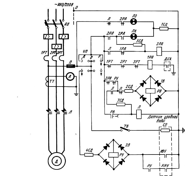
Rice. 91. Schematic diagram of a PET-type control system for deep-well pumps with electric motors I with a power of up to 65 kW
The pump is switched off by turning the handle of the universal switch to the zero position.
With automatic control, the universal switch is set to position A (automatic control). In this case, as described above, the pump will turn on and the green LZ lamp will turn off.
In this case, when the water reaches the upper level through the contacts of the KVU of the level sensor, the level switch RU will turn on, the opening contacts of which will turn off the starter L, and the pump will stop. The green lamp LZ will light up again - the pump is not working. Opening the contacts of the KVU of the level sensor does not turn off the RU relay, since the latter is powered through its contact until the water level is below the contacts of the KNU of the lower level. When the relay RU is de-energized, it will turn on again through the NC contact RU of the time relay РВ, after which the pump will start. The water level will rise again and the cycle will repeat.
The CO resistor (heating resistance), switched on by the TV toggle switch, is designed to prevent icing of the water level sensor.
Control of loading of the electric motor of the pump is made according to indications of the ammeter.
Protection of the electric motor against short circuits is carried out by electromagnetic releases of the AB machine.
Overload protection - thermal relays 1RT, 2RT and ZRT, the breaking contacts of which are included in the IP A relay circuit, whose contacts, in turn, turn off the pump through 2RA. The 2PA alarm relay contacts turn on the JIK alarm (overload) and self-block the 2PA coil through the 5SD resistor (quenching resistance), thereby preventing the pump from turning on after the thermal relay contacts return to their original position.
A similar emergency shutdown of the pump occurs when water disappears in the well (opening the contacts of the DSH dry running sensor).
Reactivation (when water appears in the well) can occur after setting the universal switch to zero and then switching it to the on position (automatic or manual).
In table. 24 shows a list of devices installed in control systems of the PET type.
Some imperfection of control systems such as PET is a violation of the control of the operation of the electric pump with significant temperature deviations environment on the temperature to which the thermal protection elements are adjusted (+ 20 °С).
At present, the Tiraspol Electrical Apparatus Plant is mastering the production of non-contact control stations for low-pressure electric pumps of the SHET-5800 type.
Non-contact control stations, complete with water level sensors and dry running sensors, are used for manual, automatic and telemechanical control of submersible electric pumps and their protection from emergency conditions.
The stations are designed to operate in a three-phase alternating current with grounded neutral at a voltage of 380/220 e.
Control stations are made in the form of protected cabinets, inside which the starting and protective equipment is mounted. Instruments, control equipment and an alarm lamp for emergency shutdown are located on the doors.
Non-contact transistor logical and functional elements of the T series (unified Logic series) produced by the Kalinin Plant of Electrical Equipment are used as control and protection equipment.
All elements are filled with a special compound mass and have stable characteristics when the ambient temperature changes from -40 to +50 °C.
The use of such equipment significantly increases the reliability of control stations and the service life of submersible electric pumps.
Non-contact elements perform the following tasks in control circuits.
Element T-101 implements the logical function "or - not". In the absence of a signal at all inputs of the T-101 element, the output has a high negative potential "1". If there is a “1” signal at any of the inputs, the output will always be a “0” signal.
The T-202 (relay) element converts a smoothly varying input voltage into a discrete output signal.
Element T-303 (time delay) provides an output signal with a time delay specified by the installation, after the input signal is applied.
The T-402 element is an output amplifier.
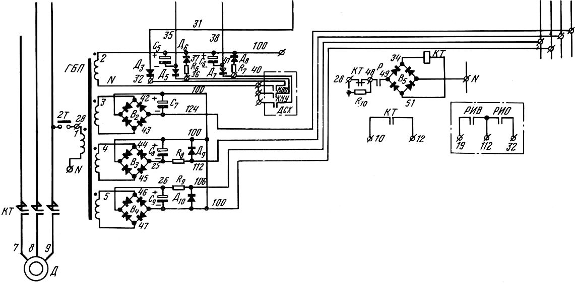
On fig. 92 shows a schematic diagram of a control station for submersible electric pumps with a power of 2.8 to 11 kw.
The station is connected by turning on the AB machine, then setting the 2T toggle switch (supply voltage) to the “On” position. voltage is applied to the power supply of the logic elements.
Rice. 92. Schematic diagram of the control station for submersible electric pumps with a power of 2.8 to 11 kW
During automatic control, the toggle switch 3T "Operating mode" is set to the "Auto" position, the toggle switch 1T "Local control" is set to the "On" position, and the jumper I short-circuits the clamps.
With telemechanical control, the toggle switch 3T "Operating mode" is set to the "Auto" position, the jumper H is removed, and terminals 5, 32 and 112 are connected to the corresponding terminals of the switch-on relay (RIV) and the switch-off relay (RIO). These relays are not installed in the station. Voltage is supplied to the coils of these relays from the telemechanical control system.
Automatic control. If there is no water in the tank and the contacts of the KNU and KVU of the level sensor are open, there is a zero signal at both inputs of the 1st element T-101 (3 and 2). As mentioned above, at the same time, there is a high negative potential (“1”) at the output of the T-101 element, which is fed to the T-402 amplifier. Relay P is turned on, and the relay turns on the magnetic starter L. The electric pump turns on and water begins to flow into the tank. When the water reaches the upper level (KVU), a zero signal appears at the input of the amplifier, and at its output the signal "1" is transmitted to the input of the 1st element of the T-101. This is how the element "Memory" is formed. Relay P de-energizes and the pump stops.
When the water level drops below the KNU contacts, a “1” signal appears at the second output of the 1st element T-101, which erases the “Memory”, the relay turns on again. The cycle is repeated.
Local control is carried out using the 1T toggle switch. The operation of the pump is controlled by an ammeter A.
Telemechanical control is carried out by the dispatcher. According to the command “Turn on the electric pump” given by him, the relay for the execution of the RIV activation is activated. Through its contact 5-112, voltage is applied to the input of the T-402 amplifier. Relay R is activated and the electric pump is switched on. On the command "Turn off the pump", the RIO shutdown relay is activated, through the contacts of which voltage is supplied to the input of the "Memory" circuit (elements T-101 and T-402). Relay P turns off, de-energizes the starter coil JI with its normally open contact and the pump stops.
The control station switches off the electric pump in case of overload, operation of the electric pump in two phases, as well as in case of a short circuit.
The alarm signal arrives at the input of the relay element T-202 from sensors - current-to-voltage converters. Using the potentiometer R1, the relay element is set to the operating current.
Element T-303 (time delay), resistor R3 and stabilizer D1 form an inverse dependence of the time delay on the current (the greater the current, the less time protection operation). After the time element, the signal is fed to the passive 5th element T-101, which serves to increase the load capacity of the T-303 element. At the same time, the signal from the output of the T-303 element is fed to the input of the 1st element of the T-101, prohibiting the start. From the output of the 5th element T-101, the signal goes to the amplifier T-402 and to the 1st element T-101, as a result of which the alarm lamp LA lights up and the pump is prohibited from starting.
The alarm signal is stored after the electric pump is turned off, since the T-303 element is assembled according to the "Memory" scheme.
To re-enable the electric pump after the accident has been eliminated, it is necessary to remove power from the elements, for which the 2T toggle switch is placed in the “Off” position.
In case of short circuits exceeding the values of the currents of the setting of the maximum releases, the circuit breaker AB.
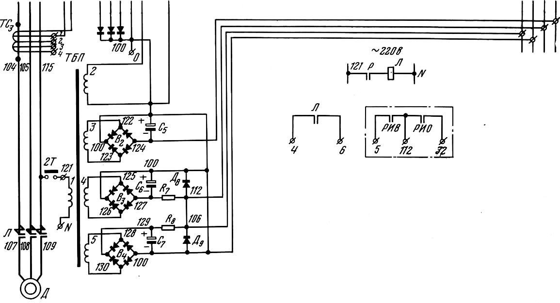
Rice. 93 illustrates the operation of the control station for submersible electric pumps with a capacity of 16-65 kw.
The station is switched on by an automatic switch AB. By setting the 2T toggle switch (supply voltage) to the “On” position voltage is applied to the power supply of the logic part.
In case of automatic control, the toggle switch ЗТ "Operating mode" is set to the "Auto" position, the jumper I is removed, and the terminals are connected to the corresponding terminals of the relay of the on version and the relay of the off version, which are not installed in the station. Voltage is supplied to the coils of these relays from the telemechanical control system.
Rice. 93. Schematic diagram of the control station for submersible electric pumps with a capacity of 16-65 kW
Automatic control. If there is no water in the tank and the KVU contacts of the level sensor are open, the 6th element T-101, assembled according to the “Memory” scheme, sends a zero signal to the 7th element T-101, which is inverted to one and fed to the T-402 amplifier. The relay R is activated and, with its closing contacts, turns on the magnetic starter (or “ontactor”). The pump turns on and water begins to flow into the tank. As soon as the KVU contacts of the water level sensor are closed, a “1” signal appears at the input of the 6th element T-101. The 7th element of the T-101 inverts this signal to the input of the T-402 amplifier. Relay P turns off the magnetic starter and stops the pump.
When the water goes below the lower controlled level of the KNU, the signal "1" from the output of the 1st element of the T-101 erases the "Memory". The relay is activated again and turns on the starter. The cycle is repeated.
Local control of the electric pump is carried out using the 1T toggle switch and is usually used during commissioning. In this case, the operation of the electric pump is controlled by the ammeter L.
Telemechanical control is carried out by the dispatcher from the control room. On the command "Turn on the electric pump", the relay for the execution of the RIV is activated, giving a signal to erase the memory (6th element T-101). On the command "Turn off the electric pump", the RIO shutdown execution relay is activated and gives a "1" signal to trigger the memory element (6th element T-101). The relay turns off the magnetic starter. The pump stops.
Protection. The control station protects the electric pump in case of overload, symmetrical and asymmetrical short circuits, two-phase operation of the pump, and “dry running of the pump” (water loss).
When water leaves the well, an alarm signal comes from a dry-running sensor installed in the well. In other cases, the alarm signal enters the logic elements from the current transformers 1ТТ-ЗТТ and matching transformers ТСi-ТС3.
At high values of short-circuit currents, the automatic switch AB is activated.
In case of overloads, phase failure or minor short circuit currents, the T-202 relay element is activated, set to a response current of 1.2 of the nominal, and then with a time delay that is inversely dependent on the current value, the T-303 time element, assembled according to the "Memory" scheme, is activated . The latter transmits a signal to the 7th element T-101 (the amplifier has a zero signal at the input) and relay P, turning off the starter (contactor), stops the pump. In addition, the T-303 element, transmitting a signal through two series-connected 8T-101 elements (which serve to increase the load capacity of the T-303 time element) to the T-402 amplifier, lights the alarm lamp L A.
When water leaves the well, the zero signal from the DSH dry running sensor is inverted by the 1st element T-101 and transmitted to the 4th element T-101, assembled according to the "Memory" scheme. After the signal is transmitted from it to the 7th element T-101, the relay is turned off and the electric pump stops, and through two series-connected elements 8T-101 to the amplifier T-402, the aircraft alarm lamp lights up.
To determine the cause of the emergency stop of the electric pump, use the buttons K1 and K2.
In cases where deep pumps are installed for dewatering, drainage and irrigation, there is no need to equip a water tower and install an electrode sensor in it.
Automatically works in the interval of marks of the upper and lower electrode sensors.
On fig. 94 shows an automation diagram using electrode sensors.
The scheme developed by the Soyuzshakhtoosushchenie trust provides automatic shutdown pumping unit in the event of a lack of water in the well or an accident with the pump.
The scheme is simple in execution and reliable in operation.
In the automation scheme, an electric floatless regulator is used, which serves to turn off the coil of the contactor of the magnetic starter 1. The regulator consists of an induction relay 2 and one electrode 3 installed on the pressure pipeline.
The laminated core of the induction relay has A-shape. The primary coil of the relay is fixed on the upper rod of the magnetic circuit, and the secondary coil, to which the electrode circuit is connected, is on the middle rod. The relay armature is connected to an insulated bar, on which there are four pairs of contacts.
An alternating current supplied to the primary winding creates a magnetic flux, which induces voltage in the secondary coil. If the circuit of the secondary coil closes, which happens when water moves through the pipeline, then the passing current in the core of the secondary coil will create a magnetic field, under the influence of which the armature will be attracted to the core.
At the same time, to ensure the automation of the operation of the pumping unit and prevent air from being sucked in by the pump, two electrode sensors are suspended in the well. The lower sensor is suspended not lower than the pump in the well.
Rice. 94. Automation scheme using electrode sensors
In the absence of water in the pipeline, the secondary coil circuit opens, the armature moves away from the core and the normally open contact opens the contactor coil circuit, turning off the pump motor. At the same time, a red lamp lights up on the signaling device panel.
The pump motor is started by closing the start button K, included in the circuit of the secondary coil of the induction relay. When this button is pressed, the relay armature is attracted, the closing contact of the relay, included in the circuit of the contactor coil, is closed, including the magnetic starter contactor and the electric motor.
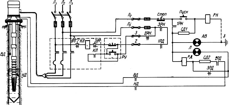
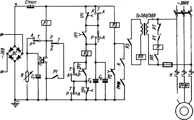
Rice. 95. Scheme of automation of a pumping unit with electrode sensors (during the construction of the Volzhskaya HPP)
The start button is held in the on position until water appears in the pressure pipe.
As an electrode installed in the pressure pipeline, can be used car candle ignition.
At the water-reducing works during the construction of the Volga hydroelectric power plant, a scheme was used to automate the pumping unit with electrode sensors suspended in the well at various elevations. The scheme provided for automatic maintenance of the dynamic level of pressure water within certain limits, excluding the possibility of raising the water level above the permissible and below the required limits. Thus, the depression funnel was automatically maintained at minimum quantity pumped water. This automation scheme confirmed its high operational reliability and provided significant cost savings in the process of dewatering work. The circuit has a control panel with a magnetic starter and an automatic prefix (Fig. 95).
Turning on the automatic prefix is as follows. When the “Start” button is pressed on the machine panel, the circuit is closed: phase L2 - button contacts. "Stop" and "Start" -relay PH - ground contact h. At the same time, the PH relay is activated and with its closing contact 1RN shunts the Start button and introduces additional resistance SD1 into the PH coil circuit. The opening contact 2RN breaks the manual control circuit, and the closing contact ZRN, closing, prepares the KL magnetic starter circuit for operation. At the same time, the signal lamp AB lights up - the machine is on.
When the water level in the well drops to the LP sensor, the relay of the RD sensors does not work, since the circuit is open by the NO contact of the HP.
After the water in the well reaches the upper level HP sensor, the RD relay closes along the circuit: phase L2 - Stop button - NO contact 1RN - RD relay coil - NC contact ZRD - NO contact V D. When the RD relay is triggered, its NO contact 2RD shunts the relay circuit, the opening contact ZRD introduces additional resistance SD2 into the circuit, and the closing contact 1RD closes the magnetic starter coil along the circuit: phase Lu - opening contact of the thermal relay 1RT - coil KL - opening contact 2RT - manual control button RU - terminal 2 - make contact 1RD - make contact ZRN - phase L3. In this case, the magnetic starter KL turns on the pump motor and the signal lamp L lights up.
Rice. 96. Scheme automatic control submersible deep pumps with an electric motor with a power of up to 6 kW
After pumping out water below the level of the lower LP sensor, the power supply circuit of the RD relay opens, the coil of the magnetic starter KL is de-energized by the closing contact 1RD, and the pump motor is turned off.
When you press the "Stop" button, the power supply circuit of the automatic attachment is interrupted and the PH relay is de-energized.
Manual control is carried out by the button RU.
Of great interest are the schemes for automating the work of deep pumps, developed by V. I. Zhizhin and justified themselves in harsh natural conditions during the drainage of the Volchansky coal pits of the Sverdlovskugol plant.
Scheme of automatic control of submersible deep pumps with an electric motor with a power of up to 6 kW (Fig. 96). When setting the toggle switch T (TV-1-2) to position A ( automatic operation) and supply voltage, the time relay RV (RKN, 12G0 ohm) is switched on, which closes its normally open contact in the coil circuit of the intermediate relay RP (RKN, 1000 ohm). The latter closes the circuit of the KP contactor coil and turns on the starter P (P-311M) of the electric pump. At the same time, the auxiliary contact of the starter K in the circuit of the intermediate relay RP is closed. The duration of holding the time relay PB in the on state depends on the setting of the variable resistance R (51 k), which is shunted by the capacitor Cx (30 V, 500 microfarads). During this time, water rises into the discharge pipeline and closes the circuit of the DP performance sensor, blocking the closing contact of the time relay RV, so that when this time relay contact opens, the circuit of the intermediate relay RP does not break and the pump continues to work.
To turn off the pump when it sucks air into the circuit, an upper level sensor DVU, a relay RVU (RKN, 2000 ohms) and capacitor C2 (30 V, 500 microfarads) are introduced. When air is sucked in by the pump, the DP performance sensor is activated and the pump motor is disconnected from the network.
Rice. Fig. 97. Scheme of automatic and local control of the deep pump ATH when working on the drain
With the filling of the well with water, the circuit of the upper level sensor of the DVU is closed and the relay RVU is turned on, which closes its normally open contact in the circuit of the intermediate relay RP.
The intermediate relay will turn on the starter and the pump will automatically turn on again. Capacitor C2 keeps the RVU relay on for 10-15 seconds after the water level drops and the contact of the RVU upper level sensor opens. During this time, the water will rise into the discharge pipeline and close the circuit of the DP sensor, blocking the closing contact of the RVU relay.
Signaling about the operation of the pump is carried out by the signal lamp JIC, in the circuit of which the closing contact of the relay RP is connected.
The automation equipment is mounted in the case of a small-sized starter, the weight of the set is less than 5 kg. Its use does not require a heated room.
Scheme of automatic and local control of the ATH deep-well pump when working to drain. To operate the circuit in automatic mode, the toggle switch T is set to position A. When voltage is applied, the time relay RV1 (RKN, 1200 ohm) is turned on, closing its closing and opening its NC contacts in the relay coil circuit RV2 (RKN, 1200 ohm), preparing its circuit nutrition. After the expiration of the time delay set by the potentiometer R (51 kΩ) and the capacitor Ct (500 microfarads, 30 V), the time relay PB1 will turn off, including the relay PB2. Due to the capacitance of the capacitor C2 (3000 microfarads, 30 V), the time relay PB2 remains on for some time. During this time, the relay P1 (RKN, 1000 ohm) turned on by him will turn on the relay RP, which will turn on the starter K of the pump motor. The pump starts pumping water. During normal operation of the pump, water, rising through the discharge pipeline, closes the circuit of the DP performance sensor, which blocks the closing contact of the PB2 relay. Capacitor C3 (500 microfarads, 30 V) keeps relay P1 on during short power outages and power ups.
At manual control toggle switch T is set in position P. When button I is pressed, the intermediate relay RP is activated and closes the circuit of the coil of the contactor of the pump motor starter with its contact. The P button must be pressed until water rises into the discharge pipe and closes the CPU performance sensor circuit.
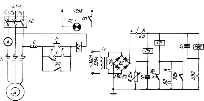
Rice. 98. Scheme of automatic control of a submersible deep-well pump with an electric motor with a power of 35 to 65 kW
To control the heating temperature of the winding and bearings of the electric motor, the ATV-229 equipment with TS thermistors (TR-33) is included in the circuit. When heated, the electrical resistance of the thermistor decreases many times and the current increases sharply. In this case, the intermediate relay R (RKN-1, 10,000 ohm) is activated and opens its NC contact in the pump control circuit.
The circuit operates on the capacitive current of the capacitors and does not require a mode sensor. It eliminates the repeated switching on of the electric motor of the pumping unit in case of a break in the transmission shaft of the pump.
Scheme of automatic control of a submersible deep-well pump with an electric motor with a power of 35 to 65 kW (Fig. 98). When the toggle switch T is set to the position of automatic operation mode A and the supply voltage is turned on by the charge of the capacitor C \, relay P1 is turned on. Relay P1 closes its NO contact 1P1 and opens its NC contact 2P1, charging capacitors C2 and C3 and breaking the supply circuit of relay coil P2.
After the capacitor Ci is discharged (from 4 to 30 seconds, depending on the setting of the variable resistance R), the supply circuit of the relay coil P1 is broken and the relay is turned off, opening the NO contact 1P1 and closing its NC contact 2P1.
In this case, the charging of capacitors C2 and C3 stops, power is supplied to the coil P2. Relay P2 is activated by closing its NO contact in the coil circuit of the R3 relay. Relay P2 is kept on for 8-10 seconds due to the charge accumulated in the capacitors C\ and C%.
During this time, the RZ relay will turn on the starter K of the pump motor. If the pump is operating normally, then the RZ relay coil circuit will be closed by the NO contact RMN of the RMN minimum load relay and auxiliary contact K of the starter contactor.
In case of underload or load shedding, the electric motor current decreases and the contact of the RMN relay in the RZ coil circuit opens. The pump will turn off.
With manual control, the toggle switch T is set to position P. When the “Start” button is pressed, relay P1 is turned on, which, closing its make contacts 1P1 and 2P1 and opening the break contact 1P1, stops charging capacitors C2 and C3 and supplies power to the relay coil P2. Otherwise, the operation of the circuit is similar to its operation in automatic control mode.
The circuit uses a selenium rectifier BC (ABC -100), variable resistance R (51 kΩ), relays P1 and P2 (RKN, 1200 ohms), relays RZ (RNA, 1000 ohms), electrolytic capacitors Ci-C3 (30 V, 500 microfarad).
For safety reasons, the control circuits are rated at 36V.
Scheme-provides reliable protection electric motor, since the starter is turned off in the absence of voltage on any of the phases and therefore the transition of the electric motor to a two-phase operation mode is excluded.
The Kurgan plant "Kurganselmash" under the project of the Research Institute of Sanitary Engineering of the Gosstroy of the USSR produces automated water pumps of the VU5-30 type for facilities with low water consumption.
The VU5-30 installation (Fig. 99) consists of a pumping unit, an air-water tank with regulating and control equipment, a pressure switch, a pressure and distribution network.
The water sucked in by the pump through the inlet valve enters through the pipeline into the air-water tank. Filling the tank, it compresses the air to the shutdown pressure and the pressure switch breaks the power supply circuit of the pump motor. When the pump is off, water is supplied from the tank under compressed air pressure. As water is used up, the pressure in the tank drops. When it reaches the turn-on pressure value, the pressure switch, using a magnetic starter, will turn on the pump motor again, and the cycle of operation is repeated.
To keep the volume constant air cushion The unit has a jet air supply regulator.
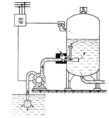
Rice. 99. Installation VU5-30
The sources of water supply for the VU5-30 pumping unit can be open water bodies, mine wells or wells with a depth of not more than 15 m to the dynamic water level, with a flow rate of at least 6 m3/h and a daily flow rate of not more than 75 m3.
TO category: - Deep well pumps
Description and application.
The start-up of any electric pumps is one of the most unfavorable conditions for their electric motors, water-lifting pipes and the water-handling part of the well. The electric motor of the submersible pump during this period is subjected to peak load for a short time, because. its starting current is 5 - 8 times higher than the nominal value with a relatively low starting torque.
In addition, the jump in the starting current creates a shock electromagnetic moment transmitted through the motor shaft to the pump impeller. Under such conditions, maximum pressure fluctuations during hydraulic shock are possible in the water-lifting pipe string, and high values of water inflow into the well from the aquifer are possible in the water-holding part.
The main reasons for the failure of the borehole pump:
- Operation with increased or reduced supply voltage in electrical network
- Overloading of the electric motor due to operation in the "dry running" mode, i.e. without water. The submersible motor is cooled by water, so without it, it quickly overheats and fails. Protection of the electric motor against overload and "dry running" is carried out: with the help of thermal current relays that turn off the electric motor in case of an accident; directly by the water level in the well, using sensors; indirectly, by the value of the power factor (cos φ).
- Ingress of coarse sand into the pumping section. A high concentration of sand shortens the life of the pump and increases the risk of blockage. The use of "floating" impeller technology in pumps of some brands reduces the effect of such blocking, but this technology is not a panacea.
- Water hammer protection is missing or does not work. For example, the accumulator tank does not work or the pressure switch “sticks” (the contacts are burnt or the relay case is in the water)
Tasks and solutions.
To eliminate the negative phenomena that occur during the start-up of submersible pumps, developed technological schemes well equipment. They are based on electrical control panels  and hydraulic components (hydraulic tanks, valves, etc.). Control panels are designed not only to protect the electric motor and the pump itself from failure, but also serve to implement one of the pump operation control schemes:
- by pressure in the pressure pipeline
- according to the water level in the storage tank
To implement one of these schemes, automation is connected to the consoles (sensors, relays, etc.). For any automatic systems, this is a favorable mode of operation: automation tools do not work with power lines, but with low-current terminals of the remote control.
The main schemes for controlling the operation of pumps.
By pressure
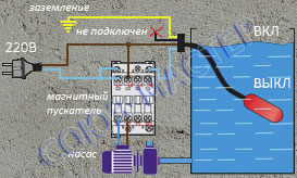
In this scheme, the pump is controlled by closing the contacts of the pressure switch located on the pressure pipeline. The pressure switch is connected via a magnetic starter to avoid high starting currents. We will only have to adjust the pressure on the pump and the pressure to turn it off.
This principle is most often used with hydraulic accumulators, for individual wells. Hydraulic tanks are needed to maintain stable pressure, prevent water hammer and frequent pump starts at low flow rates.
The relay is adjusted in accordance with the parameters of the pump and the capacity of the hydraulic tank. The set pressure range must be in the middle working area pump. Taking into account the information on the permissible number of starts (usually no more than 20 per hour) of the pump, the pressure is usually selected in the range of 2.5 bar (on) - 2.8 bar (off). At the same time, the air pressure in the accumulator should be 10% lower than the pump cut-in pressure, which in our case is about 2.2 bar.
For a well pump, a level control machine can be connected if the well was equipped with water level electrodes. The controller is based on the electrical conductivity of water. Electrodes (not included in the delivery set) are placed in the liquid from of stainless steel. Electricity, having a low voltage (10 V), flows between the electrodes through the liquid and controls the switching of the unit. The machine allows switching according to the two-electrode and three-electrode circuit. The two-electrode circuit allows you to limit the lower or upper water level, the three-electrode circuit is able to set the operating level range. With a two-electrode circuit, the pump will turn off as soon as the top electrode is without water and turn back on as soon as the water rises to it.
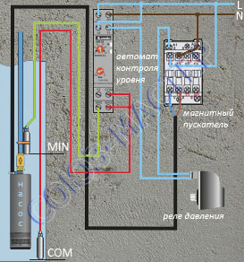
By water level
Automatic control of the submersible pump. Execution options.
| Category | Functionality | Appearance |
|---|---|---|
| Economy 2 500 rub. |
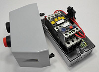
Motor-automatic. This a budget option. The device in a plastic protective box (IP54) consists of a contactor (magnetic starter) and a thermal current relay. The functions of the device are primitive and simple:
|
|
| Standard 11 900 rub. |
Complete wardrobe. This is a complete option. The device in a plastic protective box (IP65) consists of: a contactor, a current relay, a voltage relay and a circuit breaker. Device features:
|
Applications electric pumps enough. They are applied at the enterprises, summer residences, private houses. Their stable operation ensures constant water supply.
To maintain the required water level, special automation for pumps is used, which facilitates the use of pumps. There is no need to manually turn the pumps on and off. However, in the event of a breakdown, human intervention in the operation of the system is provided. There is a so-called transition to manual control mode.
1 Types of automation
Depending on the principle of operation, the following types of automation for pumps are distinguished:
- Control relay. Its function is to close and open the electrical circuit, depending on the change in pressure.
- Electrocontact manometers. There are movable and fixed groups of contacts;
- float system. Used in refillable containers;
- Pressure Sensors. Change the resistance with the passage of current, depending on the change in pressure;
- Volume counters. There are mechanical and electrical. Give a signal to the system when the required volume is reached;
- Converter. Changes the frequency of the current supplying the pump;
- Electromagnetic starters;
- Schemes for switching work to other pumps, from automatic to manual mode;
- Light equipment signaling the state of the system;
- pump protection equipment, electrical circuits, reed switch (limit switch).
1.1 The principle of operation of automation
Basically, automation works to turn it on and off, depending on the settings you have and the desired result. If the level in the liquid tank has dropped, then the float system closes the circuit and the pump turns on. When the level is reached, the circuit opens, the pump turns off. This is how automation for borehole pumps works. The control principle ensures that water is pumped out of the well.
A similar principle of operation in closed system with circulation pumps. If the pressure drops, then the sensor changes resistance, the frequency of the current increases, and the pump starts to work faster. When the required pressure is reached, the resistance changes again, and the pump starts to operate at a lower frequency.
In the case of volume meters, they close the circuit contacts in the same way, as a result, the pump turns on. When the required volume is reached, the system turns it off automatically. One example is the Turbo model.
1.2 Varieties of automation
There are two main types of automation for pumps:
- Pump control based on fluid pressure in the pipeline. This method involves the installation of a pressure switch in the water supply system. The main two parameters are configured, which are responsible for turning the pump on or off. It is used in wells in combination with membrane tanks, whose work maintains pressure in the system. It is necessary to choose the right relay, taking into account the characteristics of the pump and tank. Such relays are divided into industrial and household models. Production relays have more powerful contact groups. They must be adjusted with a pressure gauge. Handle current up to 16A. The downside is the poor accuracy in setting the desired parameters. Household relays can be connected to the network without prior configuration through the existing contact groups. They have a scale of adjustable operating ranges, which is not found in professional models. Pumps to increase water pressure work with both professional and household relays. One of the samples of automation for a home pump is the Wistan 3 model.
- Pump control based on the liquid level in the storage tank. The scheme is relevant for filling containers and raising water to water towers. A float or special electrodes are mounted inside. The upper and lower levels are set. When the water reaches the lower level, the network closes and the pump turns on. Having reached the upper level, the network opens and the pump turns off. This design must be equipped with an overflow alarm or emergency drain. The advantage of this scheme is that the pump does not turn on too often. It works only when it is necessary to fill the full capacity, and not when you just need to get water. Thus, its service life and stability of work increases. The level pump control unit is used at home when the water supply is not constant. At the pumping station, where the tank capacity is large, several pumps can be installed. Then the pump control unit will lead the mood for all of them. If one fails, then electronic automation will determine which of the pumps is faulty and turn on the other.
2 Pump protection automation
The main reason for the failure of the pump is its operation outside the permissible voltage zones. Operation without liquid is not allowed. When buying a pump, you should pay attention to the requirements for the minimum and maximum values \u200b\u200bof the voltage in the network.
It will not be possible to constantly monitor these indicators, therefore a power stabilizer is built into the system. It sets the maximum and minimum voltage values. If it is outside the allowable zone, the automation turns off the pump. On three-phase motors, asymmetry control and phase sequence are carried out. Such stabilizers protect the system from power surges using a time delay. Reliable model is Turby.
2.1 Three types of combinations of protective control automation
- Starting devices. They are ready to use devices. They are connected to the pump system, pressure switch, volume sensors. Lots of features and options to control, but it's almost impossible to make changes to the settings.
- relay blocks. They are common starters and are popular in the market. The device protects the relay, but there are few functions, and an additional circuit breaker is required for connection.
- Controls based on microprocessors. The most sophisticated security devices. They allow you to monitor temperature, voltage, resistance and phase sequence through a computer. Protects against power surges, work without water. It is mainly used in systems with deep pumps.
2.2 What type of automation to choose for the pump? (video)
Automation for a borehole pump requires adjusting the pumping unit for certain water supply parameters. Instead of a well, there may be a well.
The well pump inverter control unit should only be installed after the well has been drilled, and pumping system water supply will be collected. Adjustment of automation for the pumping station should be carried out taking into account the characteristics of the well.
A downhole pump with automation is an indispensable thing in a country house or in a private house, and if Turbo works in a system with a pump, then such a tandem will ensure stable operation.
Well pumps with automatic given time very popular. It happens that one pump with automatic Turbi provides water to the whole village.
Automation for the pumping station is installed to control borehole pump taking into account the capacity in which water will accumulate and the volume of necessary water supply.
Automation for circulation pump used for continuous water supply of the heating system. There is an adjustable parameter that determines the intensity of work.
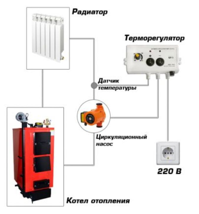
With a circulation pump, water creates pressure, due to which the liquid passes through the entire system. circulation is necessary condition water heating system.
The automatic pump control unit must be located in a dry, easily accessible place. When connecting to the pump automation, you should be aware that all characteristics must comply with the standards and instructions.
You can find out how to set up the automation of the pumping and mixing unit on the Internet, on the forums, or from the attached instructions for the automatic control system of your pumps.
The installed and configured automation unit for the pump, the connection of which was carried out correctly, will regulate all types of water supply, from a well, well or water supply. Automation provides user-friendliness by regulating the electric pump automatically. An excellent choice of control unit for a small pumping station would be the Pampela WiStan or Turbi model.
The pump control unit allows you to organize the operation of pumping equipment, avoiding dangerous moments, such as dry running or insufficient pressure. With the help of this node, the mechanism is turned on and off in a timely manner in order to prevent its breakdown.
Where is used
The pump control unit was created specifically to control the operation of pumping equipment, therefore, it can only be used in this area. However, due to the versatility of many designs, this technique can be used in almost all existing structures pumps: sewage, drainage, etc. The main task is to start the electric drives of pumping equipment of any kind (vibrating, centrifugal, etc.).
Watch the video to see how it all works:
The automatic pump control unit simultaneously performs a protective function, namely, it prevents equipment breakdown in case of changes in the recommended values of the main parameters (water supply rate, minimum pressure). Also, in case the water in the tank or well has dropped below a certain level, the automation unit also provides protection against "dry" running.
Design features
Office pumping station is more complex equipment than the classic knot. This is due to the need to connect several electric motors. Equipment of this kind is made in the form of a cabinet or shield with built-in equipment. A simpler device consists of a microcontroller that processes the incoming information (pulses from the reed switch).
Further, based on the result of these processes, the power relay starts the pumping equipment. This happens with the condition that the water flow rate satisfies a sufficient value (a certain amount of l / min.). The pre-liquid as it moves through the pump drives the flow sensor turbine.
Watch the video, the design of the device and its purpose:
If the water level is below sufficient, the dry run protection is activated. At the same time, the turbine stops, after which the microcontroller sends a signal to the relay and the latter turns off the pump. This happens with a slight delay (about 5-30 seconds, depending on the model). If the water flow is completely absent, the automatic control unit submersible pump does not include equipment called dry-running protection.
What are the options for choosing
To ensure productive functioning in the future, such a technique should be selected based on a set of basic parameters, including:
- The power of the device, which affects performance.
- Supply voltage. Most models operate in the range from 220 V to 250 V, but in order to avoid the negative impact of power surges on equipment, it is advisable to purchase versions whose supply voltage is in a wider range. For example, Automatic control of the pump Aquarobot Turbi, which can work properly when the mains voltage fluctuates from 170 V to 250 V.
- Rated current.
- Shutdown delay, which will extend the life of the mechanism, as the pumping equipment will not start more often than necessary.
- Productivity of work or speed of water supply (l/min., cubic m/h).
- Operating pressure. Usually the manufacturer specifies the range of allowable values for this parameter, however, it is not recommended to use the equipment if the maximum pressure level is reached. This is due to the fact that in such a situation the water supply rate will also be minimal, respectively, the device will turn off, as it will perceive these conditions as a transition to a “dry” run.
- Water temperature.
- The degree of protection of the case. IP 65 recommended.
To get a universal device, you should pay attention to the type of device, which will allow it to be used for pumps different designs: surface, submersible, including vibration. Today it is offered quite a large number of versions of universal automation units, such as, for example, a pump control unit of the Aquarobot Turbi M model.
Overview of characteristics of popular models
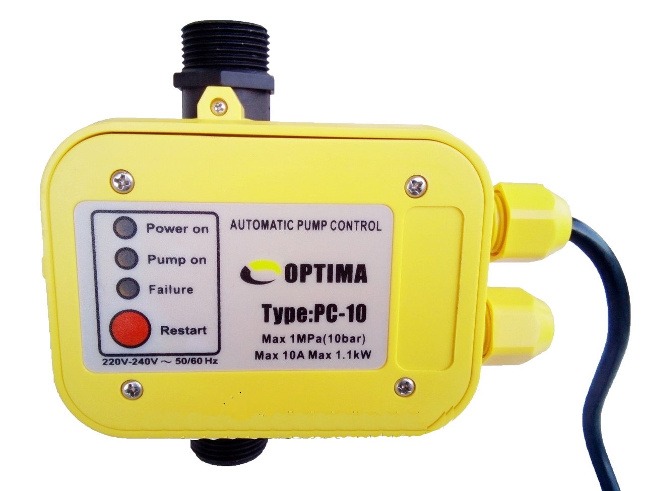
One of available options– Dzhileks the block of automation of work of the pumping equipment. Its cost in comparison with many others is very small and averages 2,500 rubles. The design provides protection against switching on in the absence of water (“dry” running). Starting pressure range: 1.5 to 3.5 bar, while the maximum limit is 10 bar. Water supply rate - 80 l / min., supply voltage 230-240 V, degree of protection of the mechanism IP 65. The device operates in water, the temperature of which should not exceed 60 ° C.
We watch a video about the products of the Gileks brand:
For comparison, the Ford Transit model is offered at a price of 6,500 rubles, which is much more expensive. This node can work with several models of pumping equipment. Another variant produces Russian manufacturer UNIPUMP, who created a line of similar equipment AQUAROBOT.
Model AQUAROBOT
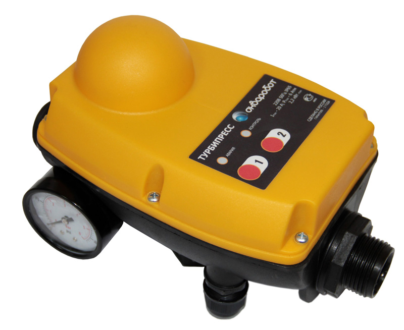
The company offers a very long warranty period for its equipment - up to 24 months, which partly indicates the high quality of products. One of the models is the Turbopress pump control unit, designed for 1.5 kW. Its price is 5,700 rubles, there is protection against “dry” running, and the unit itself can be connected to any pumping equipment.
This design works effectively with voltage fluctuations in the network from 170 to 250 V, the maximum current is 16 A.
The only slight drawback is that the maximum pressure limit is only 6 bar. But the speed of work is 120 l / min. The degree of protection of such equipment corresponds to IP 65. Another popular option is the Belamos automatic pump control unit, model BRIO-5. Like other similar designs, this unit has protection against "dry" running. The device is turned off with a delay of 5 - 7 seconds. The power is 1.1 kW, the maximum current is 12 A, the supply voltage range is from 220 to 250 V. The enclosure protection class is IP 65. The maximum working pressure is quite high - 10 bar. The cost of execution is very attractive - within 2,800 rubles.
It should be based on how expensive pumping equipment is supposed to be used along with the automation unit. Based on this, you should already decide whether to purchase a simple control unit or provide truly reliable protection for your pump. Accordingly, for cheaper equipment it makes no sense to purchase an expensive unit, the price of which will be equal to the cost of the pump itself.
Watch the video, the advantages of Acrobot systems:
One of the popular options is UNIPUMP AQUAROBOT products. The price of products of this type is slightly above average, however, users note their reliability. The Turbi pump control unit of this manufacturer has a number of advantages: versatility of use, a wide range of supply voltages, excellent water flow rate. In addition, the pump can pump liquid even at a speed of 3 l / min. As for the main parameters of such equipment, a lot of options for different brands have similar characteristics, in particular, we are talking about the degree of protection, the pressure limit value and electrical parameters(current, mains voltage).
Thus, when choosing, you should be guided by several properties and functions of the automation node at once. At the same time, the efficiency of the equipment directly depends on the compliance of the values of the parameters of the automation unit with the conditions of its operation. Most convenient option is a universal control unit, which will allow in the future to acquire different kinds and brands of pumping equipment without reference to the type of automation unit. Key Features when choosing are: water supply rate, maximum pressure value, supply voltage, current, degree of protection of the mechanism and water temperature at which such equipment can be operated.


