Finally, the long-awaited moment comes when the created device begins to “breathe”, and the question arises: how to close its “insides” and give the design completeness so that it can be used comfortably. This question is worth specifying and deciding what the case is intended for.
If it is enough for the device to have a beautiful appearance and “fit” into the interior, you can make a case from sheets of fiberboard, plywood, plastic, fiberglass. The body parts are connected with screws or glue (using additional “reinforcement”, i.e. slats, corners, gussets, etc.). To give it a “marketable appearance,” the body can be painted or covered with self-adhesive film.
A simple and convenient way to make small cases at home is from sheets of foil fiberglass. First, all components and boards are laid out inside the volume and the dimensions of the case are estimated. Sketches of walls, partitions, board fastening parts, etc. are drawn. Based on the finished sketches, the dimensions are transferred to foil fiberglass, and blanks are cut out. You can make all the holes for the regulators and indicators in advance, since it is much more convenient to work with the plates than with a ready-made box.
The cut parts are adjusted, then, securing the workpieces at right angles to each other, the joints with inside soldered with ordinary solder with a fairly powerful soldering iron. There are only two “subtleties” in this process: do not forget to give allowances for the thickness of the material on the required sides of the workpieces and take into account that the solder contracts in volume when it hardens, and the soldered plates must be firmly fixed while the solder cools so that they do not “sink.”
When the device requires protection from electric fields, the housing is made of conductive materials (aluminum and its alloys, copper, brass, etc.). It is advisable to use steel when shielding is required and magnetic field, and the mass of the device does not matter much. A case made of steel, sufficient to ensure mechanical strength of thickness (usually 0.3 ... 1.0 mm, depending on the size of the device), is especially preferable for transmitting and receiving equipment, since it shields the created device from electromagnetic radiation, interference, interference, etc. .
Thin sheet steel has sufficient mechanical strength, can be bent, stamped, and is quite cheap. True, ordinary steel also has a negative property: susceptibility to corrosion (rust). To prevent corrosion, various coatings are used: oxidation, galvanizing, nickel plating, primer (before painting). In order not to deteriorate the shielding properties of the housing, its priming and painting should be done after complete assembly (or the oxidized strips of panels in contact with each other should be left unpainted (with a detachable housing). Otherwise, when assembling the housing parts “paint on a chamfer", cracks will appear that break the closed shielding circuit To combat this, spring “combs” are used (spring strips of oxidized hard steel, welded or riveted to the panels), which, during assembly, ensure reliable contact of the panels with each other.
The metal case made of two U-shaped parts is deservedly popular.(Fig. 1), bent from plastic sheet metal or alloy.

The dimensions of the parts are chosen so that when they are installed one into the other, a closed case without cracks is obtained. To connect the halves to each other, screws are used, screwed into the threaded holes in the shelves of the base 1 and the corners 2 riveted to it (Fig. 2).

If the material thickness is small (less than half the thread diameter), it is recommended to first drill a hole for the thread with a drill whose diameter is equal to half the thread diameter. Then, by striking a round awl with a hammer, the hole is given a funnel-shaped shape, after which a thread is cut into it.
If the material is sufficiently plastic, you can do without corners 2, replacing them with bent “legs” on the base itself (Fig. 3).

An even more “advanced” version of the rack, shown in Fig. 4.
Such a rack 3 not only fastens the upper panel 1 with the lower 5, but also fixes the chassis 6 in the body, on which the elements of the device being manufactured are placed. Therefore, no additional fasteners are needed, and the panels are not “decorated” with numerous screws. The bottom panel is attached to the stand using screw 2 passing through leg 4.
Thickness required material depends on the size of the case. For a small case (volume up to approximately 5 cubic dm), a sheet with a thickness of 1.5...2 mm is used. A larger body requires, accordingly, a thicker sheet - up to 3...4 mm. This primarily applies to the base (bottom panel), since it bears the main force load.
Manufacturing begins with calculating the dimensions of the workpieces (Fig. 5).

The length of the workpiece is calculated by the formula: 
Having determined the length of the first workpiece, it is cut out of the sheet and bent (for steel and brass, the bending radius R is equal to the thickness of the sheet, for aluminum alloys- 2 times more). After this, the resulting dimensions a and c are measured. Taking into account the existing size c, determine the width of the second workpiece (C-2S) and calculate its length using the same formula, substituting:
- instead of a - (a-S);
- instead of R1 - R2;
- instead of S - t.
This technology guarantees precise connection of parts.
After manufacturing both halves of the body, they are adjusted, marked and mounting holes are drilled. In the necessary places, holes and windows are cut for control knobs, connectors, indicators and other elements. The control assembly and final adjustment of the body are carried out.
Sometimes it is difficult to fit all the “stuffing” of the device into the U-shaped half. For example, on the front panel you need to install a large number of display and control organs. It is inconvenient to cut windows for them in a bent part. A combined option will help out here. The body half with the front panel is made from separate sheet blanks. To attach them, you can use special corners shown in Fig. 6.

This part conveniently fastens three walls at once in the corner of the case. The dimensions of the corners depend on the dimensions of the structural elements being fastened.
To make a corner, a strip of mild steel is taken and fold lines are marked on it. The central part of the workpiece is clamped in a vice. With light blows of a hammer, the strip is bent, then turned over so that the bent part lies on lateral surface vice, and the middle part was slightly clamped. In this position, the bend is corrected and the deformation of the strip is eliminated. Now the second side of the part is bent, and, after editing, a ready-made fastening unit is obtained. All that remains is to mark the location and drill the holes in which to cut the threads.
Equipment, especially lamp equipment, requires housing ventilation. It is not at all necessary to drill holes throughout the entire body; it is enough to make them in places where there are powerful lamps (in the top cover of the case), on the back wall above the chassis, several rows of holes in the central part of the bottom cover of the case and two or three rows of holes on the side walls (in the upper part). There should also be holes around each lamp in the chassis. Above powerful lamps with forced ventilation Windows are usually cut out and a metal mesh is fixed into them.
IN Lately, as a result of rapid obsolescence, cases from computer system units appeared in landfills. These cases can be used to create various amateur radio equipment, especially since the width of the case takes up very little space. But such a vertical layout is not always suitable. Then you can take the casing from the system unit, cut it to the required dimensions and “join” it with a “cut” from a second similar casing (or separate panels - Fig. 7, 8).


With careful manufacturing, the body turns out to be quite good and already painted.
To make reliable, high-quality and durable housings for various types electronics you can do it yourself. This, of course, will require some skills and effort, but it will help you save a lot cash(factory aluminum cases and even ordinary plastic structures are very expensive).

To make a homemade analogue of an electronics housing, take a 40-centimeter piece of profiled galvanized pipe with a rectangular section of 100x50 (such dimensions will allow you to effectively dissipate heat). It is desirable that the pipe wall thickness be no more than 3 mm. For small electronics, the dimensions used should be slightly smaller - 40x20, and the pipe wall thickness should be 2 mm. You can purchase such pipes in specialized construction stores. You will need the bare minimum of tools - only a drill or screwdriver (for drilling holes), as well as a grinder (directly for cutting the pipe).


Cut from profile pipe 18 cm - this will be the body itself. His side walls, also obtained by cutting from a pipe, must be fastened with 4 pins passing through the corners along the length of the entire body. In this case, they will not interfere with the placement of all the necessary parts inside. To ensure optimal clearance for rapid cooling, cut the 20/20mm profile to create two L-shaped corners. Screw them in from the sides to make an excellent wall mount.


A homemade metal case with sufficient thermal conductivity, which, due to its considerable weight, is more suitable for stationary use, ready. All that remains is to give it an attractive appearance, i.e. cover with spray paint, having previously primed and degreased the surface so that the paint goes on more evenly and lasts longer.
The circuit is assembled, configured... How much effort went into the circuit, searching for parts, assembly, configuration, and there is not much left - the body!
It is no secret that a good body plays a very important role and gives the structure a finished look. It often takes a long time before someone gets around to making the case. What is it most often made from?
- plywood (wood)
- fiberglass (getinax)
- duralumin
- plastic
- parcel box :)
- buy ready-made
I have a problem with wood, well, I can’t work with it cleanly, I need good tool and enough space in the apartment. Fiberglass - I did it, I didn’t really like it. You have to find duralumin, and it’s a bit expensive these days. I personally am not ready to buy ready-made. Either there are no suitable sizes, or the price is confusing.
In general, all that remains is to either make it from plastic or from a parcel box and suffer that none of your friends will appreciate the work of assembling the board.....
So.
I chose plastic. Where can I get it? 
In repair companies (firms, offices), with familiar system administrators. Anything will do: old keyboards, blanks from CD-ROMs, FDDs, parts from printers, copiers (workshops usually give them away with gratitude - after all, they are junk) and just plastic from something else. You can use plexiglass. The main thing is that it dissolves in dichloroethane. 
Tool
There is not much of it: a metal ruler, a square, a cutter (made from a piece of cloth), a hacksaw for metal, files with a coarse notch, sandpaper (I take hardware store, type P600 (fine grain) and P100 (coarser) from Kona flex) and dichloroethane plastic adhesive. Also, it is necessary to dissolve finely chopped pieces of plastic in dichloroethane, the consistency should be like thick syrup. We will glue and fill small cracks with this solution.ATTENTION! Dichloroethane is toxic and volatile.
Begin
I cut plastic with a hacksaw with a sharp blade, not very quickly, so that the plastic does not heat up. Nothing bad will happen, it will just be difficult to saw if the plastic softens. I file the edges. If it is necessary to level the edge or adjust the size, I do this using coarse sandpaper. I lay a sheet of sandpaper on a flat surface, grain side up, and without putting much effort I move the edge of the workpiece along it. The main thing is to distribute the force evenly over the workpiece.We glue
You need a flat surface, for me it’s a piece of chipboard.I apply glue with a thin brush to both surfaces several times and press firmly; if it is a corner, I control it using a square. If it is necessary to glue two small pieces into one, then I lubricate the ends with glue, press the ends together tightly flat surface. Attention! Be sure to reinforce corners and joints with strips of plastic.


Treatment
After gluing, I begin processing the front surface. Large scratches, cracks with front side I fill it with a mass of plastic dissolved in dichloroethane. After drying (about 10-12 hours), I sand the surface until it is even.
That's it - the body is ready for painting. 
This is what happened after the final finishing. 
The part about circuitry was mercilessly cut out - we can do that ourselves.
Making an amplifier is not as difficult as it seems. All work can be done at home in the kitchen, with a minimum set of tools and materials. But nevertheless, you can get impressive results. In this article I will tell you how to do this. I will also not use machines and will do all the work by hand.
For the case you will need an aluminum square 15X15 millimeters, more is possible, but not less, otherwise the case will not have sufficient rigidity. First you need to cut the workpiece.
I recommend that you first draw the body on paper and calculate all the dimensions, so that later it will not be excruciatingly painful. When I make cases, I proceed from the fact that all standard Hi-Fi class devices have cases 430 or 460 millimeters long, and their height and depth are not limited. The size 460 millimeters seems too big to me, so I took the size 430 millimeters. I plan to trim the body itself with glass 4 millimeters thick. It follows that the frame must be smaller in size than the final size of the amplifier. If there is a glass lid of 4 millimeters and a bottom of aluminum 1.5 millimeters thick, then the height of the frame should be 5.5 millimeters less than the planned size. And if you make the sides glass, then you need to subtract two glass thicknesses from the total length.
Well, the blanks are cut, you can start processing. Let's start with the vertical posts of the frame. Here, too, we must not forget that from their height we must subtract two thicknesses of the shelf of the square used. In my case, with a total amplifier thickness of 60 millimeters, a glass cover thickness of 4 mm, a bottom of 1.5 mm, and a thickness of the angle shelf, the height of the stand was 51.5 millimeters.
I processed all the racks with a package, this will allow them to be the same height.

When the racks are ready, we begin processing the horizontal frame elements. Each end of the square must be cut at an angle of 45 degrees for convenient joining. You can draw it using a school square (I promised not to use a professional tool).

Pay attention to the next two photographs; they show how to cut off the end of the square.


The bevel should go to the shelf, forming sharp corner. Can be pre-sawed most metal with a hacksaw, and finally finish it with a file. Make sure that all similar parts are the same length. To assemble a case with dimensions 430X250X60, you will need four squares 422 millimeters long, and four squares 250 millimeters long. An hour later I had all the blanks done, and I started assembling the frame.

I will assemble it using M3 screws, it was possible to rivet it, but rivets have now become scarce, and rivets are not suitable for this purpose - their heads will stick out. The screws must be purchased with a countersunk head and the drill must be sharpened at an angle of 90 degrees to drill recesses for the screw head.

Two squares are assembled on one vertical rack, as shown in the picture.

And this is the view from reverse side.

For greater accuracy, you can drill by holding the parts in a vice.

It should look like an aquarium.

Now we need to make the bottom and back wall. I made them from aluminum sheet 1.5 millimeters thick. But it can be applied roofing iron or plexiglass - it won’t be worse. You just have to recalculate the height of the racks. I used a jigsaw to cut out the blanks, but you can cut them in any available way.

When cutting, do not try to get it to size right away; it is better to make it a millimeter larger and finally adjust the protruding edge into place. Here, the bottom is ready. It must be screwed to the frame with screws with a pitch of no more than one hundred millimeters, this will prevent it from deflecting.

Now you can cut the protruding part of the bottom to size.

The back of the body is done in the same way. The power connector, input and output jacks will be installed on it. They must be purchased in advance.

Mark and drill holes in the back wall.

Well, everything is simple here - the holes are round, but you will have to tinker with the power connector.

We mark the place for the future window and use a thin drill to drill holes as close to each other as possible. Then we cut the jumpers with side cutters...


Five minutes of file work and the window is ready!

Now he’ll think about the legs of our future amplifier. They can be used ready-made from an old computer case, but I found legs from a suitcase that are made of soft plastic. They fit perfectly.

You can start making the front panel. I made it from an aluminum strip 5 millimeters thick, but this is not critical, it can be thinner, just a thick panel looks somehow more beautiful.

In the picture you can see some markings, this is what I forgot to mention. Specifically in this amplifier, I wanted to make a dial level indicator. There must be some kind of zest. But you can do without indicators; those who do not do them can safely skip the entire description about indicators.
Indicators... For them I purchased two voltmeters.

And took them apart...

Of these, we only need the mechanism itself. It must be handled with the utmost care.

To give the indicator a professional look, we will combine them in one housing and provide backlighting. On aluminum plate We transfer the markings from the original nameplate and cut them out with a needle file.


And we also need to make a bar that will cover the mechanism from prying eyes.

It should look something like what is seen in the photo.

It is worth paying attention to the side covers - they are needed to complete the structure. And three more holes in the center - LEDs indicating the enabled input will be located there. This is what it looks like from the back.

The entire structure is supported by a square, which is located in the middle. The illumination will be provided by a strip of blue LEDs. They are located in the upper part of the case, above the indicator.

Three red LEDs must be glued into the holes located in the center of the indicator.


Well, we solder a board with resistors to the terminals. The LEDs themselves are connected in parallel to the relay windings on the switching board.

We need to cut a window under the indicator; we will use the same technology as when cutting a window under the power connector. Only here you need to show maximum accuracy and patience - the appearance of the amplifier will depend on this.

Here I couldn’t resist and milled out a recess for the glass on the back side, but this is not necessary. You can use a thin transparent film for laser printers; this film is very thin and will not affect the dimensions, which cannot be said about glass.

The holes for the buttons are drilled with an 8.4 mm drill. This is because I have an eight millimeter diameter aluminum rod that will make great buttons.

It is best to make a chamfer in a hole using a countersink; it is difficult to achieve a flat surface with a drill.

The button itself is sawed off from the rod required length and sanded by hand using hand drill. On the reverse side you need to drill a 4 mm hole. It is advisable to polish the end.

The power switch is attached to two long screws, this will allow you to accurately set its height so that the button does not rub in the hole.

You can use a ready-made volume knob; this will not worsen the appearance. There are such beautiful pens on sale.


But I don’t like it, I used a homemade one. If you have a turner friend, I advise you to ask him for help and make a handle like this.

And for complete completion, you need to make a decorative ring.

In combination with the handle, this will take on a completely finished look.

But I’ll say it again - this is not necessary, it will look great with a different handle. Work remains on finishing the body. The front panel must be sanded thoroughly. To do this, let's assemble a small device.

The panel is fixed on a chipboard base, a square is screwed to the side - it serves as a guide. A strip of medium-grit sandpaper is attached to a section of the same chipboard. The sandpaper is moved along the panel and at the same time pressed against the guide. This will allow you to get parallel risks on the panel.

When processing, the panel must be watered generously with kerosene. It can be poured into a spray bottle, it will be very convenient. The panel must always be damp. Don't rub it dry! Hard-to-remove defects may remain.

In an hour you will be able to admire the results.

The volume knob can be polished using a drill.


All that's left to do is cut out the glass to finish the case. I used a mirror for this gray. The simplest thing is to order all this from a mirror workshop, but you can do it yourself. Cutting glass is not a problem, but processing the edges requires effort. Processing is carried out sandpaper with water. By gradually decreasing the numbers, you can achieve almost perfect polishing. But you can also stop at a flat matte surface.

The side strips of glass are glued to the body using aquarium silicone.


The glass is glued into the recess using epoxy glue. After curing, excess glue is removed with a sharp blade.

Assembling the indicator. The picture for the nameplate is drawn in any graphics editor and printed on self-adhesive white film.

It would also be good to order decorative linings for screws from a turner, they will add professional look amplifier.

The body itself is covered with black spray paint, but this is also not necessary - the frame is almost invisible. If the case cover is made of glass, by the way, an ordinary mirror gives good results, you need to drill holes in it. I made them using a tubular drill. First, up to half the thickness on the back side of the mirror...

And then from the front. If you do it the other way around, you won’t be able to see where to drill, and I don’t recommend drilling all the way through - in this case, chips are inevitable.

Now we take a red LED with a diameter of three millimeters. A hole with a diameter of three millimeters is drilled in the volume knob on the front side, and on the back, almost to the end, it must be drilled with a four millimeter drill. A resistor is soldered to the LED, and the wires are insulated with tubes. It is advisable to use MGTF brand wire.

The resulting structure is inserted into the hole and secured with a drop of glue.

The handle is put in place, and the wires are passed through the gap between the panel and the axle. The wires from the LED are connected to the supply voltage.

That's it now! All that remains is to secure the top cover. It is also advisable to place decorative pads under the screws. But you can use black screws.

The final step is to make the inscriptions on the front panel. The easiest option is to print them on transparent self-adhesive film. That's exactly what I did.

This is what you should end up with.


Without bragging, I will say that this work took me sixteen hours. So this amplifier is quite possible to build in a weekend. Good luck!
This publication will talk about making the front panel for a homemade amplifier, and will also tell you a little about how I planned the amplifier case. I'll tell you about in a simple way writing on metal surface front panel, as well as other useful things when planning and manufacturing a case for a homemade UMZCH.
Power amplifier housing
Before starting to design the amplifier case, I needed to solve the problem of choosing radiators for cooling the powerful KT825+KT827 transistors. Installed radiators will occupy a fairly large area in the body or on the body of the UMZCH. For every two channels of the UMZCH there are 4 transistors - a total of 8 transistors, you need to distribute them among the radiators.
At first I thought of installing all the transistors on two long radiators - 4 transistors for each, which would act as the side parts of the case, but I did not find a radiator profile of the required height and heat transfer area.
After digging through the household trash, compact radiators with a fairly large heat dissipation area were found, on which old KT805A transistors in a metal case were installed.
Rice. 1. Radiators from KT805A transistors.
Having slightly estimated the location of these radiators on the sides, I was already thinking about abandoning the idea of using them, especially since there would be a lot of fuss with attaching the KT825, KT827 transistors in the TO-3 case; I would have to drill holes and remove a small layer of metal with a file or cutter.
At the same time, my father came to visit me in my room, and after talking a little about the housing for the ULF, I decided to use these radiators.
All transistors were installed on 8 radiators; for mounting, an insulated mounting with mica was used as a dielectric and heat conductor, and white thermal paste from the same KT805A that was originally installed on the radiators was used.
I talked about the isolated method of installing transistors in a TO-3 package on radiators earlier in an article on making an UMZCH circuit on the TDA7250.
Having the radiators available and playing a little with their location, I began to draw a plan for the amplifier housing in AutoCAD (now I use the free LibreCAD for drawing).
Good to know: to convert *.dwg files for AutoCAD into *.dxf format for LibreCAD and other programs, a converter program called “Teigha File Converter”, which is freely available under Windows, Linux, Mac OS X and Android, has proven itself quite well .

Rice. 2. Hull plan for homemade amplifier in AutoCAD.
In terms of width, I tried to make the amplifier body the same as many domestic ULFs, for example, like that of Radiotehnika-U101. Thus, the width of the rear panel, on which the connectors and terminals of the amplifier will be attached, is 150mm.
The length of the amplifier case turned out to be equal to the length of three radiators + the thickness of the front panel. In the middle of the body will be installed toroidal transformer, and then I’ll figure out how to place all the other electronics.
The rear panel should contain:
- 4 RCA connectors (tulip) for connecting signal sources;
- 4 fuse holders for AC + 1 fuse holder for 220V power supply;
- 1 IEC connector (like a computer power supply) for connecting 220V power;
- 2 terminal blocks WP4-7 for connecting 4 speaker systems;
- 1 COM port, in case I find time to do control via a computer.
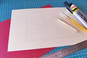
I designed the placement of components on the rear panel the old fashioned way - on a sheet of paper in a box:

Rice. 3. Layout of connectors on the rear panel of the power amplifier, drawn on a piece of paper.

Rice. 4. Finished back panel for a homemade power amplifier.
All connectors and fuse holders were placed quite compactly and conveniently. Before attaching them, the panel with the cut holes was painted White color with help aerosol can with paint.
For the bottom of the amplifier case, an aluminum plate approximately 2mm thick was cut out to fit the resulting rectangle of radiators and rear panel.
For the future front panel of the power amplifier, a piece of duralumin 5mm thick, 75mm high and 450mm wide was cut out.

Rice. 5. Blanks for the amplifier case - radiators, rear panel, bottom and plate for the front panel.

Rice. 6. Housing of a homemade UMZCH assembled.
Amplifier Front Panel Layout
Having an almost finished amplifier case and a plate for the front panel, I began planning the latter, drawing what should be placed and how and in what dimensions.
On the front panel there are:
- Output power indicators - 4 rows of 9 LEDs (5mm) each;
- Power button;
- Two-color LED (5mm) - power and standby indicator;
- 4 switches PR 2-10, each with 10 positions - volume controls for each channel;
- 2 switches for the ability to disable any of the two pairs of channels;
- Headphone jack;
- Indication panel - component temperatures, modes, overload, fan status.

Rice. 7. Front panel plan for a homemade Phoenix P-400 power amplifier.

Rice. 8. Plan of the front panel of the amplifier with coloring and without indicating dimensions (without headphone jack).
I liked this layout and decided to start implementing it, all that remained was to add some inscriptions and see how everything would look:

Rice. 9. Plan of the front panel of the amplifier with inscriptions for the controls.
Making the front panel of the amplifier
Having a clear plan and preparation, you can start working. With the help of sandpaper + effort + patience, all the depressions, paint residues and the consequences of slight oxidation were removed from the duralumin panel.
When eliminating surface defects, I made movements with sandpaper in the way that was convenient, that is, in different directions, in different directions and corners. Upon completion and after inspection, it was decided to perform additional (finishing) grinding, which would correct the cosmetic appearance of the plate.
To do this, it was necessary to repeatedly walk with sandpaper along the entire panel, evenly and in one direction (for example, from left to right). After such grinding, the plate looked quite neat and nice.
Afterwards, in accordance with the drawing that was drawn above, I began marking the places for drilling holes for the control and display elements using a ruler + square + compass + pencil. Before drilling, it doesn’t hurt to mark the locations for the holes with a core.
The holes for the LEDs were made with a drill with a diameter of 5 mm, as practice has shown, only a few holes had to be brought to the desired diameter of the LEDs using a small round needle file.
The holes for the switches (power supply and controls), button and jack were drilled with a drill of the maximum suitable diameter, but if you can’t find one, it doesn’t matter, a smaller one will do, then you can bring the diameter to the desired value using a round file.
There was one more difficult test left - to make a rectangular hole measuring 136x45mm for the amplifier display panel. Having weighed the choice of available means, I identified several solution options for myself:
- We drill holes with a diameter of approximately 5 mm around the entire perimeter of the rectangle, one next to the other. Then we get rid of the partitions between the holes and remove the cut piece of the plate. You can cut the partitions using a needle file or a jigsaw (stock up on nail files in advance). Afterwards, using files, we remove all the irregularities and align the shape of the cut rectangle as much as possible.
- This option came to mind after analyzing the previous one. Its essence is simple - we drill one hole, for example in the corner of a rectangle, gather all our patience, insert the jigsaw needle into the drilled hole and begin to cut out the rectangle along the drawn contour.
Having assessed the amount of fuss in the first and second options, I decided that the second option is simpler and will allow us to get a more accurate result. When I started, I didn’t even suspect that about two hours of hard work, about a dozen broken jigsaw files and several calluses on my hands awaited me... the desire to get the desired result helped me achieve my goal!
Everything turned out very neatly and I only had to slightly correct the entire perimeter of the rectangle using a flat file. I can't advise anyone this option, because cutting metal with a diameter of 5 mm with a jigsaw is a very difficult task, perhaps even a little crazy. I used what I had on hand at that time; I definitely wouldn’t do that now - I would go somewhere to a factory and they would make everything much simpler.
Applying inscriptions to the front panel of the UMZCH
I think that this item will be of interest to many, especially those who make various housings for metal devices, not just power amplifiers.
I believe that many of you are familiar with or have at least once heard somewhere about such a phenomenon as Laser Ironing Technology or simply among the people - LUT. I also heard at one time, but without even trying it for the manufacture of printed circuit boards (always, in the old fashioned way, a stencil was drawn by hand on a sheet of paper + a syringe with varnish for applying to PCB), I began to use it for applying inscriptions to metal.
The essence of LUT is simple, now I will describe in detail how I applied the inscriptions to the duralumin plate for the front panel of the amplifier.
We clean the metal with fine-grained sandpaper, ensuring that the surface is even and smooth (I have already done this, described above). We clean and degrease the surface of the plate using a cotton swab dipped in solvent.
We print on LASER printer the required stencil with all the necessary inscriptions and in several copies on a page removed from a durable glossy magazine. Printing must be done with a mirror image, so that after interruption the inscriptions on the metal will be in correct position. You can display the image in any graphic editor or using the program in which the drawings were drawn.

Rice. 10. Stencil with inscriptions for the front panel of my amplifier.
If the printed design is large enough in size, then it may be better to cut it into smaller pieces, I did just that - I separately cut out stencils for the inscription on top, for each of the volume controls, headphones...
It is more convenient to center the drawing in small parts, inner part The paper of the prepared piece of stencil can be cut and pressed into the hole, thereby reliably centering it.

Rice. 11. Inscriptions printed on a magazine sheet of paper and in mirror image for the front panel of the UMZCH.
We heat up the iron, I used a Soviet one with a solid massive metal sole, it cools down slowly and, accordingly, accumulates enough heat for heat transfer.
Using an iron, heat a metal plate to a temperature slightly lower maximum temperature iron, this is done “by eye”, and besides, the plate cools down quite quickly - you can heat it up to maximum and then take a short pause before the next step.
In my case, the plate is quite long, so I transferred the inscriptions in order and first heated one side of the plate and transferred the inscriptions, then proceeded to the inscriptions in the middle and heated the middle of the plate, and then the remaining side.
The process of transferring the inscriptions is very simple - we apply the stencil, center it and position it as needed, then we put the sole of the iron on top of the stencil and hold it there for 10 seconds, after letting it cool for 10 seconds we begin to gently “rub” the stencil over the entire area.
Having glued several stencils in this way, you can move on to the next stage. You can, of course, glue all the stencils at once, but it’s up to you to decide which one is more convenient for you, try it and determine the appropriate option for yourself.
We are looking for a bowl or basin with dimensions sufficient to immerse the plate being made into it. We collect warm water with a temperature of approximately 30-35 degrees Celsius into the found container. Carefully place in a container with warm water our plate with glued stencils. We wait about 10-15 minutes so that the paper is completely soaked and easily peels off from the metal, separate it and wipe the panel with the inscriptions with a piece of dry cloth.
We wait a little while for the inscriptions on the panel to dry - thin layers of white fibers will become visible on them - these are remnants of paper. We remove these fibers using cotton wool soaked in alcohol, we do this carefully and with little effort.
We repeat the process of degreasing (you never know, we still get it dirty with our hands) of the metal in the next area where we need to glue the inscriptions, heat it with an iron, put the stencil, heat it, and then rub it in, soak it in water, wipe it... repeat until all the inscriptions are applied.
That's it, the inscriptions are ready!
It may happen that you won’t be able to get complete and high-quality inscriptions the first time - don’t despair, try and experiment. I printed stencils on sheets of paper from different magazines, only two types of paper were given good result- they soaked well and peeled off from the toner transferred to the metal.
Varnishing and display panel
After applying all the inscriptions to the metal, the front panel was varnished using an aerosol can of clear varnish. I varnished it several times over two days. After waiting for everything to dry well, I began making a tablet with display elements.
Above I have given a plan of the front panel and it already shows indication LEDs, as well as digital indicators; in the middle there is an area for drawing a picture - a small Phoenix.
In principle, you can make an opaque panel and place everything as is, but I wanted something more interesting - the Phoenix will glow, and instead of protruding LEDs, the inscriptions will glow!
How to implement this? - print a film lining on which only the inscriptions, holes for digital indicators will be transparent and in the middle there is a translucent phoenix design.
I drew the basis of the stencil in AutoCAD, then converted it into a drawing and opening it in Photoshop, added a Phoenix drawing in the middle, and also added small turtle pictures that will glow red when the maximum set power is exceeded (these LEDs are connected to every 10th channel of the output LED indicators power).

Rice. 12. Stencil for the display panel of a homemade amplifier.
Icons with an exclamation point "!" will be highlighted when the speaker protection is triggered, as well as when the amplifier starts (speaker turn-on delay and click suppression).
The “On” inscriptions will glow green if the pairs of UMZCH channels corresponding to each side are turned on using the switches. The inscription “Fan” will light up when the cooling fans of the transistors of the UMZCH output stages start working. Icons with the index "t" are constantly highlighted under each of the digital segments, which display the temperature level from 9 to 0:
- For UMZCH transistors of the left pair of channels;
- For toroidal transformer;
- For amplifier chassis;
- For UMZCH transistors of the right pair of channels.
The solution with temperature levels looks a little confusing, but nevertheless quite informative. Now, if I were making a similar UMZCH, I would make the indication with normal thermometers and on microcontrollers, but at that time what came to mind from budget and available options- and then he implemented it.
Having saved the drawing to a PDF file (Portable Document Format from Adobe), I went to the printing house, where within a few hours they provided me with the finished result in several copies on transparent film.

Rice. 13. A stencil printed on film for the amplifier display panel.
The display panel will be hidden behind a 3mm thick rectangular plate of organic glass (plexiglass), which will be placed in a rectangular hole in the front panel of the amplifier. Behind this plate will be placed a stencil printed on film, and behind it will be screwed an indication board with Phoenix backlighting, indicators and LEDs.
All display components must be placed on a printed circuit board, which must be designed to match the manufactured stencil. To design such a printed circuit board on a sheet of checkered paper, I printed out a stencil of the display panel, placed it on a sheet of paper with a future signet and marked what should be where, and later, using a pencil, I began to draw the tracks.

Rice. 14. How I once drew printed circuit board for the display panel.
To illuminate the picture with the Phoenix, small-sized yellow light bulbs with a voltage of 5V were used. It was possible to use yellow LEDs, but at that time I did not have enough of them.
If there are no yellow light bulbs or the glow is not sufficiently colored, then you can place a brightly sized piece of paper under the drawing yellow color- this will give an even and soft glow effect to the pattern.
Top cover for amplifier housing
WITH top cover everything is quite simple - I cut it to the same size as the bottom of the amplifier. A large Titan cooler is installed in the middle of the cover to cool the transformer and the internals of the power amplifier.

Rice. 15. Titan cooler for cooling the power amplifier.
A protective mesh was later installed on the cooler, taken from a non-working PC power supply.
For effective ventilation four sets of holes were drilled into the lid, each with three rows. They are placed equally spaced on the sides.
In order to make a hole in the cover for the fan, we used the method of drilling holes around the perimeter (in this case, a circle), which I wrote about above when making the front panel.
The top cover will be attached to the radiators using small knurled screws, this is very convenient if you need to remove the cover and replace the fuse or to clean dust - unscrewing six of these screws is a matter of minutes and no screwdriver is needed.
After all the holes were drilled, the panel needed to be painted. I decided to paint it black, since the knurled screws are silver and the cooler is also silver - they look good against a black background. I painted it in two layers, letting them dry enough, using an aerosol can with black paint.
Finishing touches and some notes
To use multi-position switches as step variable resistors (volume controls), the required resistances were selected experimentally. Depending on the resistor values, you can make the adjustment linear or logarithmic - whichever you prefer.
Here is the connection diagram and resistance values in my version of the regulators:

Rice. 16. Diagram of a step volume control based on a multi-position switch.
Four rubber feet with a height of approximately 13mm were screwed to the bottom cover of the case (bottom), this will allow you to install the amplifier on any surface without fear of scratching it, and will also add a slight dampening of noise from the case on which several fans rotate (important for quiet listening ).
You can also screw two handles to the sides of the front panel - this will make it more convenient to carry the amplifier, and it will add a plus to the appearance. The front panel is secured with four screws to the side radiators.
I sealed the holes with the screws with small black rubber bands - these are the adhesive rubber feet that come with the network switches(Networking Switch) of medium and high cost, I did not use them when working with switches, since the switches themselves were mounted directly on the wall.
Result

Rice. 17. These are the inscriptions on the front panel of the amplifier.

Rice. 18. Appearance power amplifier assembly.

Rice. 19. Appearance of the power amplifier turned on with the fan grid installed.

Rice. 20. Rear view of the amplifier with connected signal cables, power cable and one speaker cable.

Rice. 21. Exterior view of the power amplifier on the right side.
Conclusion
This is how it turned out to be a homemade product that still serves well today. When making this amplifier, I tried to put a piece of myself into it, to make it original and at the same time simple and reliable to use. I think everyone interested will find something useful in this article.
Get creative, gain experience, try not to repeat the mistakes you’ve made before! Everything will definitely work out!