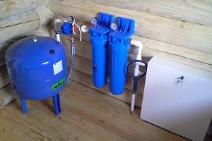
A correctly chosen scheme for connecting a hydraulic accumulator for water supply systems will ensure ease of use, as well as the durability and economy of the system. The hydraulic accumulator is important node a water supply system in which water and compressed air are separated by a membrane.
When the parameters of the water flow change (pressure decrease), the pump turns on and water is pumped into the accumulator, restoring the parameters of the required maximum pressure and then turns off. Further consumption water is coming from hydraulic device, preventing frequent switching on of the pumping unit, which occurs before next moment pressure drops to the minimum threshold. In addition, hydraulic accumulators can provide system operation for some time (depending on the volume of the tank) when there is a power outage or pump damage.
IN general view All hydraulic accumulators consist of the following main parts:
- body with legs
- membrane (in some models it is replaced by a rubber pear located in the body according to the “vessel in a vessel” principle),
- nipple for air injection, usually equipped with a protective cap.
Some products have distinctive design features:
- horizontal models are complemented by a tap or valve for bleeding air,
- equipment for drinking water is supplied with “pears” made of special grades of rubber, chemically neutral and not giving liquid foreign odors or tastes,
- hydraulic accumulators for heating systems are expansion tanks.
According to the type of location, two types of models are distinguished:
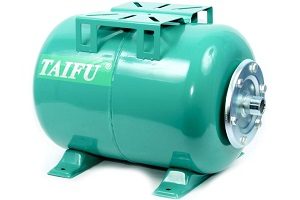
- Horizontal products are more often used for external pumps. Pumping units in such cases are installed on hydraulic accumulators.
- Vertical models are more often equipped with water supply systems with submersible pumps.
The choice of configuration and installation of a hydraulic accumulator for water supply systems at the same time can be carried out for reasons of free space for mounting a particular model.
By purpose, the following types of accumulators are distinguished:
- for cold water supply (the most popular option, used not only in houses with permanent residence, but also in cottages),
- for hot water supply, made from materials capable of withstanding high temperatures and installed during the installation of a complete system, including cold and hot water supply
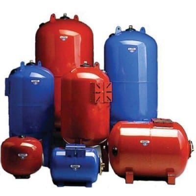
Heating accumulators are painted red, and equipment for water supply systems (cold water and hot water) - blue.
Connecting a hydraulic accumulator to a submersible pump
The connection diagram of the accumulator to the submersible pump must be include check valve. Its presence will not allow compressed air through the membrane to squeeze water back into the well. The valve is mounted immediately on the pump, before connecting other elements of the system.
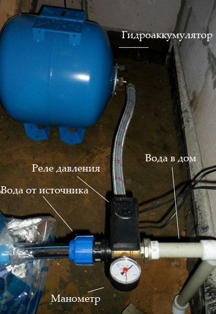
 In the photo, the connection diagram of the accumulator to the submersible pump
 The first step is to install submersible pump. To do this, using a rope and a load, the depth of the well is determined, after which a place on the rope is marked, to which it will be necessary to lower the pumping unit so that it is at a distance of 20-30 cm from the bottom. After fixing the pump, its pressure pipe or hose that goes to the surface is connected to the pressure switch using a manifold (fitting) for five connectors. A hydraulic accumulator and a water supply system are connected in series to the same collector for supply to consumption points. The remaining connector is used to connect the equipment control system.
Connecting a submersible pump to a hydraulic accumulator, like the other systems described below, necessarily requires all connections to be sealed. For this, it is used FUM tape or tow with sealant.
Connection to a surface pump
Before you start connecting the accumulator to a surface pump, you need to determine the required water supply parameters, in particular, decide what pressure is needed in the system. It is believed that water supply with a small number of points of consumption can operate at a pressure of 1.5 atm. Depending on the availability of equipment that requires a large pressure, this value can increase up to 6 atm., More high pressure considered dangerous for communications and connecting elements.
Considering the selected pressure as nominal, it is determined which decrease is appropriate to consider acceptable, that is, at what value will the pump turn on. The critical value is set on the control relay, and from the side of the nipple, the air pressure in the accumulator is measured in the absence of water in it. The resulting value should be lower than the minimum allowable by 0.5-1.0 atm.
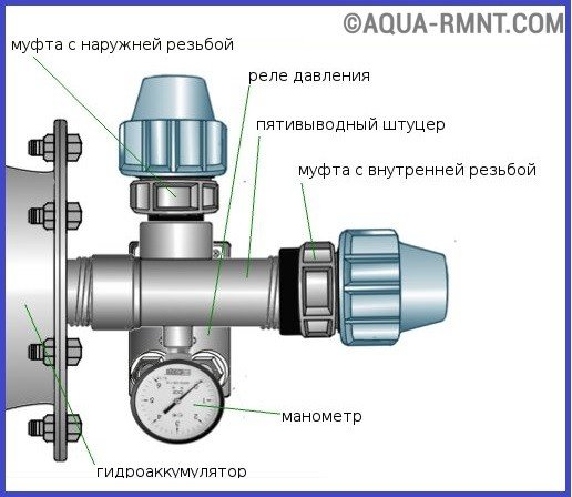
 The scheme for connecting a hydraulic accumulator to a surface pump is the same as when connecting pumping station, which already includes a hydraulic accumulator
 If no adjustment is required in this direction (for example, pumping with a pump), a hydraulic accumulator connection diagram for water supply systems is assembled
using a five-way manifold. The accumulator is installed first, then in series: pump pressure pipe, domestic water supply, pressure switch, pressure gauge.
A good owner is obliged to provide his house with a water supply system that provides comfort at any time of the year. But in the process of installing water supply systems, a problem often arises - how to maintain the necessary pressure inside the water supply system, which is necessary for the normal operation of household appliances, a bathroom, a shower, etc.? This issue is easily solved by installing a hydraulic accumulator.
A hydraulic accumulator for water supply systems is a metal container, inside of which there is a rubber membrane (pear). Hydraulic accumulators for water supply are used to accumulate a certain amount of water under pressure. When drawing water, water from the accumulator is supplied to the system.
Depending on the purpose, hydraulic accumulators are divided into:
- hydraulic accumulators for cold water supply;
- hydraulic accumulators for supplying hot water;
- hydraulic accumulators for heating systems (expansion tanks)
The cold water accumulator, in addition to the accumulation and supply of water, protects the water supply from water hammer and protects the pump from frequent switching on. The hot supply accumulator has no fundamental differences, except for a membrane capable of operating at high temperatures. Expansion tank designed to compensate for the expansion of water in heating systems. Below we will take a closer look at accumulators for cold water supply systems.
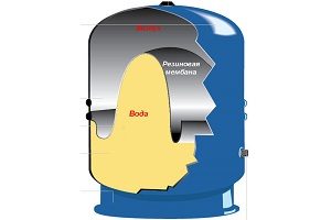
DEVICE
As mentioned above, the accumulator is a metal tank with a rubber membrane inside. The membrane is attached to the tank body using a flange equipped with an inlet pipe. Inside, between the tank body and the rubber membrane, there is compressed air, which is pumped in with the help of the most common car or bicycle pump. When water is drawn into the membrane, compressed air resists the expanding membrane and prevents it from rupturing, and also helps to create the desired pressure in the system.
HYDROACCUMULATOR DEVICE
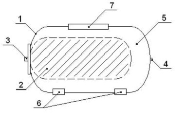
1 - metal case. 2 - membrane for water. 3 - flange with a bypass valve. 4 - nipple for air injection. 5 - space for compressed air. 6 - legs. 7 - platform for a surface pump.
HYDROACCUMULATOR OPERATING PRINCIPLE
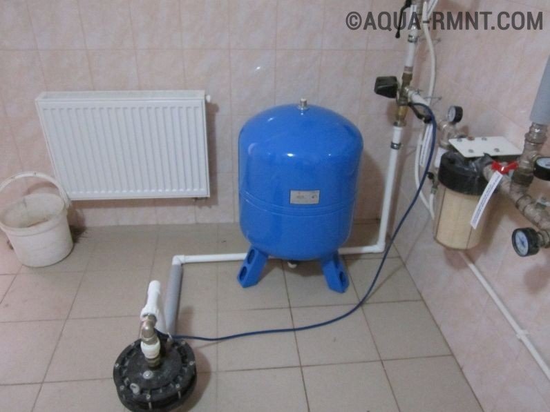
The water supply system, equipped with a hydraulic accumulator, works according to the following principle: a pump from a well (well, water supply) supplies water through a water main to a rubber membrane until a certain pressure is reached. Pressure (from 1 to 3 atmospheres) is set using a relay-regulator. When the pressure in the membrane reaches a predetermined level, the pump automatically turns off. After that, when the draw-off point starts to work (the tap is opened, the washing machine is turned on, etc.), the pear begins to squeeze water into the system. When the pressure in the pear drops to the lower mark, the relay automatically turns on the pump. The volume of the accumulator tank affects the frequency of switching on the pump - the larger the tank, the less often the pump will turn on. In this case, both the pump and the flange with the bypass valve will last longer. The tank itself is no external loads is not exposed, so it is not necessary to additionally fix it. The hydraulic accumulator can be installed simply on the floor, on regular supports.
CHOOSE A HYDROACCUMULATOR
Manufacturers produce hydroaccumulators of the most different sizes and volumes - from 24 to 1000 liters. It is necessary to choose a hydraulic accumulator based on the amount of water that is consumed in the house. For minimal needs (kitchen, toilet, shower, watering beds), it is enough to buy a container of 24 liters. But if the water consumption is significant, there are many water consumers, then you should buy a larger hydraulic accumulator. In this case, you need to estimate how many people and units household appliances can use water at the same time, and based on the conclusions made, choose a suitable container. If there is a need to increase the water flow with a ready-made water supply system, then you can replace the installed accumulator with another, larger volume, or simply add another container to the system.
HOW TO CONNECT A HYDRAULIC STORAGE DIAGRAM FOR A SURFACE PUMP
Before starting the installation of the accumulator, it is necessary to check the air pressure in the tank, which should be 0.2 - 1 bar less than the pump start pressure (set on the relay).
To connect the accumulator to the pump, you need:
- Union with five outlets;
- Relay-pressure regulator;
- pressure gauge;
- FUM tape, or tow and sealant.
A five-pin fitting is required to connect the pump, accumulator, pressure gauge and relay. The fifth outlet in the fitting is used for water pipe, which goes into the house to the water points. First, the fitting must be connected to the tank through a flange with a bypass valve, or through a rigid hose. Next, a pressure gauge, a pressure switch and a pipe leading from the pump through which water flows are screwed to the fitting.
Separately, it is worth considering the connection of a pressure switch. First you need to remove top cover relay. Below it are four contacts labeled "pump" and "network". We connect the wire coming from the pump to the contacts labeled "pump", and the wire connected to the network to the contacts labeled "network".
Attention! Some manufacturers produce relays without labels - if you are not sure about the correct connection of the relay, you should contact a professional electrician.
All threaded connections must be sealed with FUM tape or tow and sealant. After that, you can turn on the pump. In the process of water entering the system, you should carefully inspect all connections for leaks.
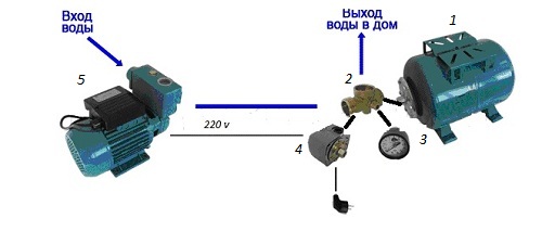
1 - hydraulic accumulator. 2 - five-pin fitting. 3 - manometer. 4 - relay-pressure regulator. 5 - surface pump.
HYDROACCUMULATOR WIRING DIAGRAM FOR SUBMERSIBLE PUMP
The submersible pump is located directly in the well or well, from where it supplies water directly to the water accumulator. The water supply system with a submersible pump must be equipped with a check valve. The valve is necessary so that the membrane does not squeeze water back into the well (well). The check valve is most often installed directly on the pump, in front of the water supply pipe. Sometimes on the pump cover they cut internal thread. In this case, you should use a fitting of the required diameter, which has an external thread on both sides. After installing the check valve, a pipe is connected to it for supplying water to the accumulator.

![]()

Measuring the length of the pipe from the edge of the well (well) to the pump is quite simple. To do this, you can use a regular rope with a load at the end. The load is lowered to the bottom, and the top point of the well or well is marked on the rope. After that, the rope is pulled out, and the length is measured from the load to the extreme point of the well. From the result obtained, you should subtract the distance from the top point to the place where the pipe from the well will go into the ground, and the length of the pump itself with a check valve. The length of the pipe must be calculated so that the pump hangs above the bottom of the well at a height of 20-30 centimeters.
Stable, working well water supply network- the real merit of the owner country house. Everyone involved in installation and maintenance autonomous system, knows how difficult it is to foresee water supply failures that are dangerous for household appliances. One pressure jump and there is a risk of breakage dishwasher or gas water heater. To warn possible problems, you need to contact a specialist or connect the accumulator with your own hands.
The device and types of accumulators
Before you start connecting the accumulator, you need to get acquainted with its constituent parts and the purpose of each of them.

Hydraulic accumulators of blue color designed for water supply systems. Expansion tanks for heating systems are red
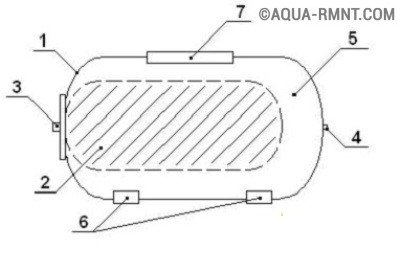
Scheme of the hydraulic accumulator device: 1 - metal case, 2 - membrane, 3 - flange with valve, 4 - nipple for air injection, 5 - compressed air, 6 - legs, 7 - pump platform
A hydraulic accumulator is a metal tank, inside of which there is a pear-shaped rubber membrane. A rubber (rubber) membrane is attached to the body by a flange with a branch pipe.
The accumulator stores water under pressure. Pressure in household appliances(1.5 bar) is created using air, in production models - inert gas.
Compressed air can be pumped into the housing using a bicycle or car pump. When water enters the tank, the compressed air prevents the bulb from bursting by providing resistance. With the help of it, the pressure in the accumulator is also regulated. In the process of drawing water, water from the apparatus moves into the system.
Hydraulic accumulators are somewhat different in their purpose, so they can be conditionally divided into 3 types:
- For cold water. It supplies and accumulates water, protects equipment from water hammer during pressure surges. Protects the pump from wear during frequent switching on.
- For hot water. Its difference is the ability to function in a high-temperature environment.
- For heating systems (expansion tanks). They are an important part of heating systems. closed type.
The place of the accumulator in the water supply system
The pump pumps water from a well, well or water supply through pipes into a hydraulic accumulator, or rather, into a rubber membrane inside it. The process continues until the pressure reaches a certain point. The required pressure is set on the relay-regulator, usually it is 1-3 atmospheres. When the desired pressure is reached, the pump switches off (automatically).
Let's assume it's turned on washing machine, shower or faucet in the kitchen - water from the membrane immediately flows back into the pipes. At the moment when the pressure reaches the lower threshold, the relay is activated and turns on the pump again. Thus the cycle begins anew.
The video below will give a complete picture of how the accumulator works:
The frequency of switching on the pump directly depends on the volume of the accumulator. The larger its tank, the less often the pump turns on. Accordingly, the less often the pump is turned on, the longer the flange with the valve and the pump itself last. The equipment is placed on the floor or mounted on the wall. In any case, its body does not suffer from operation.
Connection using a surface pump
Consider step by step how to connect the accumulator to the water supply system if a surface-type pump is used.
- Checking the air pressure inside the tank. It should be 0.2 - 1 bar less than the indicator indicated on the relay (to turn on the pump).
- Preparation of equipment for connection: fitting for 5 outlets (used to connect the accumulator, relay, pump and pressure gauge; one more outlet, the fifth, is needed to connect the water pipe); manometer; tow with sealant or FUM tape; relay for pressure control.
- Connecting the fitting to the tank. The connection can be either a rigid hose or a flange equipped with a check valve.
- Alternate screwing of the remaining elements: relay, pressure gauge, pipe leading to the pump.
Testing the system for leaks. Special attention give connections.

The connection diagram of the surface pumping station is similar to the connection diagram of the pump
When connecting the pressure switch, we carefully study the labels. Under the cover are signed contacts: "network" and "pump". The main thing is not to mix up the wires. If there are no marks under the relay cover, a specialist (electrician) should be called for connection.
During connection, it is necessary to monitor the sealing threaded connections. For a tighter fit, use tow (technical linen) with sealant or FUM tape.
Wiring diagram using a submersible pump
A submersible pump is different in that it is located in a well or in a well, that is, right in the place where water is supplied to the house, in this case, to the accumulator.

Scheme of installing a hydraulic accumulator in a water supply system with a well
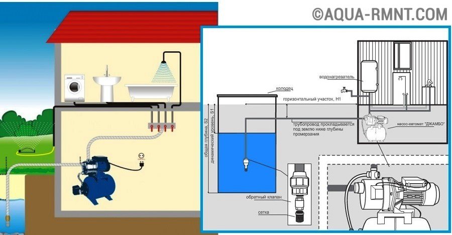
Installation diagram of a hydraulic accumulator with a submersible pump in a well
Here important role a check valve plays, which insures the system against water flowing back into the well (well). The check valve is mounted in front of the pipe, directly on the pump. To do this, an internal thread is cut into its cover. Therefore, the fitting will have external threads on all sides. First, a check valve is mounted, then the accumulator is connected to the water supply system.
An approximate diagram for connecting a hydraulic accumulator is as follows:
Having installed the fitting, it is necessary to check the tightness of the connections
To measure the length of the pipe leading from the submersible pump to the edge of the well (well), a rope with a load is used. Having lowered the load to the bottom, the upper edge of the well is marked on the rope. I will stretch the rope, you can calculate the length from the bottom to the top point. Subtract the length of the pump and the distance from the place where the pipe goes into the ground to the top of the well. We also take into account the location of the pump: it should be about 20-30 cm from the bottom.
Which accumulator model to choose?
Manufacturers, responding to consumer requests, produce equipment of various sizes. The "corridor" of volume indicators is 24-1000 liters. What should be considered when choosing?
The volume of the tank depends on the amount of water consumed
The determining factor is the amount of water needed to service the house (possibly personal plot). The minimum tank volume - 24 liters - is enough for a family of 2, if we take into account the shower, toilet, kitchen and watering the crops on the site.
More significant water consumption requires a tank with a volume of 50 liters or more. You should calculate how many household appliances use water at the same time, add the number of people who also use water, and, based on this, select the necessary model.
It happens that the number of users has increased or a new household appliance has appeared that uses water. In this case, you should simply replace the tank with a large tank, since connecting a hydraulic accumulator with your own hands is a quick and easy process.
Autonomous water supply system for modern home- this is not new. High-quality water supply devices have been tested by users and time.
But it is better for buyers to familiarize themselves with the functionality of all devices of an autonomous water supply system before purchase and installation.
Kinds
In order to properly pump water long time, a diaphragm expansion vessel is required.
For the convenience of the system and saving space, three types of these devices are on sale:
- floor;
- hinged;
- flat.
Specialist's note: when choosing between types of expansion tanks, remember that only the floor tank has a replaceable membrane.
What exactly adds an expansion tank to the system:

Operating principle
 Fluid pressure builds up in the system. Then storage tank filled with a certain volume.
In it, the water compartment gradually increases, and the opposite compartment containing air decreases.
This process continues until equilibrium is reached, in other words, desired pressure in system. When the pressure drops below the level of air pressure, timely contraction of the inner membrane occurs.
Due to it, the water supply is normalized. The tank device functions as long as necessary to stabilize the pressure of water and air.
The right choice of instrument
 When choosing a model with the necessary functions and volume, consider the fact that the frequency of the pump depends on the total volume of the tank.
The leading characteristic for any tank is not the functionality, but its volume.
At the same time, for each water supply system there are criteria that cannot be neglected, namely:
- Number of permanent water users. (Daily use).
- Number of points for water intake. (Appliances, faucets and other plumbing fixtures).
- Approximate frequency of use of water intake points at the same time.
- On-off cycle. You need to know exactly the one-hour limit of this cycle for your pump.
Approximate calculation:
When calculating for three permanent consumers, a tank with a total volume of 20-24 liters is installed. However, pumping equipment should produce approximately 2 cubic meters per hour.
When counting on four regular users with a margin, it is better to install equipment from 50 liters. The pump capacity in this case is approximately 3.5-3.7 cubic meters per hour.
If there are more than 10 consumers, then a tank of at least 100 liters is required, and pumping equipment with a rate of more than 5 cubic meters per hour.
 To avoid breakage and expensive repairs, you need to carefully read the manufacturer.
In this choice, chasing a cheaper and dubious brand is not necessary. Incorrect savings can lead to breakdowns in the future.
Models with a low retail price inside are made, as a rule, without defects. But consumables are always made from the cheapest materials.
It is better to ask about the material from which the membrane is made. Its environmental friendliness and stability will improve comfort as well as the life of the system.
How is it different from a hydraulic accumulator
 Scheme of installation of a membrane expansion tank membrane tanks and - these are the devices that are most in demand in modern device plumbing and heating.
But it is better to know their significant differences, because the expansion tank creates the effect of pressure smoothing when the liquid is heated.
talking plain language, if there is no necessary space for water, which gradually changes its volume, then any non-plastic container will burst. For this, a device with a membrane was created, which normalizes the difference in a working system.
Both devices are appearance very similar. But their device, purpose and operational characteristics are different.
 The hydraulic accumulator is used to supply water for drinking.
Its main property is the supply of the desired water pressure.
The most important part in the tank and accumulator is the membrane.
The material from which it is made is different in devices for supplying water, including between the tank and the accumulator.
The arrangement of the chambers for air and liquid is also different. The accumulator inside is equipped with a “pear” tank. Air exerts pressure on it, it is between the walls of the tank and the water tank.
For each of the above devices, the most important parameter is the durability and reliability of the membrane. Its quality guarantees the stability of the entire system.
Watch the video in which the specialist explains how to choose a membrane expansion tank for home water supply:
In the cold season, when it is cold and damp outside, when you want comfort and warmth, it is especially important to have good system heating and water supply. And in order to avoid interruptions in their work, it is worth paying attention in advance to such an important element as an expansion tank for water supply. The reliability and durability of these life-supporting systems depend on its technical condition.
Expansion tanks are integral attributes of water supply systems, heating systems, as well as fire extinguishing systems. There are two main types:
- Expansion tank open type . It is a container, at the bottom of which there is a connection to the pipe of the heating system. It is characterized by the dependence of the water level in it on the total volume of liquid in the system. The higher the temperature of the water, the greater the indicator of its volume. The tank is located at the highest point of the heating system, usually in the attic of the building. To reduce heat losses through its walls, the container is thermally insulated. An open expansion tank is leaky, unaesthetic, bulky, and therefore not suitable for indoor placement.
- Closed type expansion vessel or diaphragm expansion vessel. It is a sealed metal container-capsule having an oval or spherical shape. Inside, it is separated by a membrane made of heat-resistant rubber. As a result, two chambers are formed - liquid and air. A valve is installed inside the air compartment, designed to bleed (bleed) air at the time of a strong increase in pressure. Thus, the liquid occupies the internal volume of the tank.
Nuances of choice
In order to carry out correct selection expansion tank, you need to know exactly the total volume of the coolant.
In addition, his choice should be based on strict compliance with the maximum allowable pressure range in the heating system.
Membrane type expansion tank design
You need to know that the overestimation of the declared volume of the expansion tank for its operational parameters, as well as for the operation heating system in general, it has absolutely no effect. And finally, when choosing, it is worth calculating the expansion tank, taking into account the fact that a limited volume inside the tank is allocated to the coolant. And the indicated initial excess and maximum allowable pressure values, taking into account the coefficients corresponding to each of them, determine the most most the total volume of the expansion tank reserved for the coolant.
It is important to know! The operation of a tank characterized by an underestimated volume of water will invariably entail negative consequences. It is obvious that its use at the moment of maximum thermal loads, that is, when the pressure in the system approaches the maximum permissible values, will lead to the flow of the coolant in the places of the threaded connections of the tank or to the formation of cracks. An expansion tank for heating, used when the system is operating at low thermal loads, will cause a decrease in pressure in the system, and as a result, a decrease in the volume of the coolant. As a result, atmospheric air seeps into the container.
Typically, membrane-type tanks are produced with a non-removable membrane, which is rigidly attached to the tank section. The outer surface of the container is covered with red enamel, and the inner cavity, which is in direct contact with the working medium, that is, the heat carrier, is covered with a special moisture-resistant paint.
Worth paying attention! Unfortunately, there is no universal material for the manufacture of membranes. But still, in the process of choosing a tank, you should pay attention to the type and quality of the membrane.
Any membrane has the following performance characteristics:
- Operating temperature range;
- sanitary and hygienic requirements;
- durability;
- dynamism of the system;
- resistance to water diffusion.
Video: how to choose an expansion tank
The principle of operation of the expansion tank
If we analyze the principle of operation of a membrane-type expansion tank, then it is as follows: the coolant heated in a closed circuit expands, when the volume increase reaches the tank capacity, the membrane expands, thereby reducing the proportion of air space similar to a piston (that is, air is compressed). During this period, the pressure in the tank of the expansion tank, and accordingly in the entire system, increases. When the water temperature drops, its volume in the heating system decreases. In addition, the pressure also decreases, so the previously accepted water is pushed back into the system by means of compressed air.
It is important to know! Before you install an expansion tank in your own home, even at the selection stage, you need to make sure that you have a quality certificate, and in some cases a safety certificate. It is in this case that you can be sure that the selected element of the heating system will be reliable and functional.
If there is a slight leakage of fluid, then the pressure in both the system and the expansion tank falls, and compressed air squeezes out the reserve volume of water, thus replenishing the heating system. First stage operation of the heating system involves circumstances in which the pressure of the coolant will be to a certain extent greater than the hydrostatic pressure of the system. For this reason, the liquid chamber of the expansion tank receives the coolant in an amount that corresponds to the operating losses. With an increase in the volume of the liquid chamber of the tank, the volume decreases and the pressure in the air chamber of the tank increases. Thus, the established pressure is the initial operating pressure of the heating system.
Now you can easily pick up an expansion tank with the required volume
Video: how a hydraulic tank works
Key points during installation
Of course, the installation of an expansion tank requires a professionally drafted project, as well as installation instructions.
Initially, the tank is supplied with gas that fills the entire internal volume and is under overpressure. Just before execution installation work the tank is charged to the pressure, the value of which is pre-calculated.
The installation of an expansion tank is accompanied by the following features:
- A container larger than 500 liters may not fit through a standard doorway.
- Invalid installation check valves and filters on the branch connecting the expansion tank and the heating system.
- The connection of the expansion tank must be made taking into account further maintenance. And it requires installation. stop valves on the branch to the tank, and in such a way as to prevent accidental closure.
- Piping section: The tank shut-off valve must be equipped with a drain cock.
- In close proximity to the installation site, the connection diagram of the expansion tank must include the installation of a pressure gauge and a safety valve.
Connection diagrams for expansion tanks for water supply


Video: how to connect an expansion tank to a water supply system
Expansion tanks for heating systems usually mean thermal power up to 6 MW. If the operation of heating systems of greater power is implied, then due to constant water leaks, it is required to ensure round-the-clock uninterrupted operation of the make-up pumps.


