Hydraulic accumulator, hydraulic tank or membrane tank - necessary element for a closed, autonomous water supply system in any private house. These devices are designed for:
1. Accumulating water and ensuring the required and constant pressure in the water supply system;
2. Reduce the frequency of switching on the pump, which helps to increase the life of the pump;
3.Prevention of the system from water hammer, when the pump is suddenly turned off or on;
4.Maintaining a reserve amount of water in the event of a power outage. In hot water systems, accumulators are used to compensate for thermal expansion.
Device and principle of operationhydroaccumulator
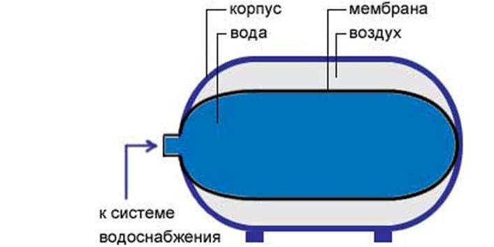
Hydraulic accumulator is a hermetic, metal container, inside which is locatedelastic membrane , which divides the container into two parts. In one part is pumped under pressure inert gas orair, and the other is water. Water isin the water chamber-membrane anddoes not come into contact with the metal case. The membrane is made of durable EPDM rubber material that meets all hygienic and sanitary standards drinking water. There is a pneumatic valve (spool) in the air chamber, air pressure regulator.
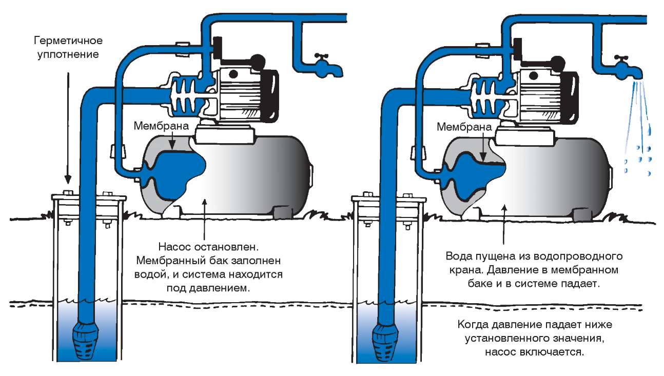
Water is supplied to the water supply system and hydraulic accumulator using a pump. As a result, the pressure V water supply network
increases. When it reaches certain, predetermined values, system automatic control turns off the pump and the water supply stops. With a small volume water intake, the accumulator will give this volume, the pressure in the system will drop, but the pressure switch will not turn on the pump. When taking a larger volume of water and achieving lower pressure mark , set on the relay,the pump turns on and starts pumping water to compensate for its consumption.
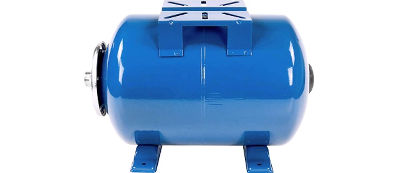
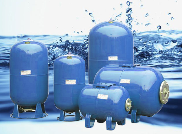
Hydraulic accumulators can be vertical and horizontal configuration. Hydraulic accumulators for water supply and expansion tanks for hot water systems designed for temperature up to 80 degrees C and pressure up to 12 atm.
The choice of accumulator
What type of hydraulic accumulator to choose?
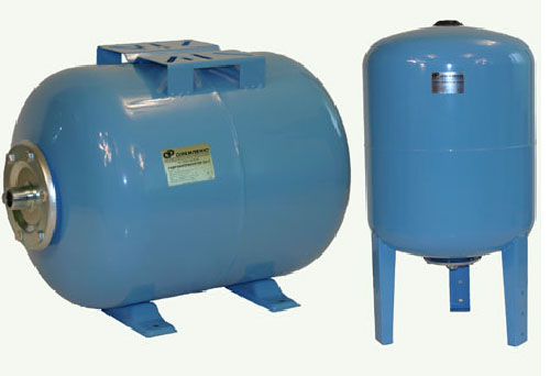
Depending on the shape of the body, this equipment is divided into two types - hydraulic accumulator horizontal And vertical. The choice of the tank shape is carried out based on the size of the room where it will be installed, guided primarily by the availability of free space in the room. If the free space allows you to install any of the modifications, and the volume of the accumulator exceeds 100 liters, it would be more expedient to purchase a vertical model. The fact is that in water supply systems there is always dissolved air in the water. Over time, during operation of the system, this air is released from the water and accumulates in various places, forming air pockets.One of these places is the top of the accumulator. inside the rubber membrane.
In a vertical accumulator, the area of the upper part is smaller, which facilitates the process of bleeding air. This is usually done with a specialair release valve.
In hydraulic accumulators horizontal type air removal can be done using an additional section of the pipeline with a valve.
In hydraulic accumulators of small volumes, the removal of air accumulated in them is carried out by periodically turning off the power supply to the pump and bleeding the accumulated air through the draw-off point closest to the accumulator.
How to choose the volume of the water supply accumulator?
Properly selected volume hydraulic accumulatorfor water supply systems provide not only pressure stability in the individual pipeline, but also to extend the life of the pump and communications.
Exists a large number of initial data to be taken into account:
1. The number of equipment that requires water to operate;
2.Number of people water users;
3. The number of allowable pump on / off per hour.
4.P pump performance
The nominal volume is selected taking into account the fact that the accumulator during normal operation is switched on about 15 times per hour. In this case, the basic parameter in the calculations is the volume of water consumption.
Below are several ways to calculate the volume of a hydraulic accumulator:
1. Depending on the type of installation and pump power.
Surface pumps:
power up to 1 kW -
horizontal model 24 l .
power over 1 kW -
horizontal model for 50 l.
Submersible pumps:
power up to 500 W - horizontal or vertical model for 24 liters.
power up to 1 kW -
horizontal or vertical model for 50 l.
power up to 1.5 kW -
horizontal or vertical model for 100 l.
2. By the number of draw points.
Up to 3 points of water analysis, a pump with a capacity of about 2 cubic meters. m/h - hydraulic accumulator up to 24 l.
- up to 8 points water analysis, a pump with a capacity of about 3.5 cubic meters. m/h - hydraulic accumulator 50 l.
- more than 10 points water analysis, a pump with a capacity of about 5 cubic meters. m/h - hydraulic accumulator 100 l.
3. By performance parameter
The calculation is performed according to the formula:
O = K*Rmax*(Dmax + 1)*(Dmin+1)/(Dmax-Dmin) - (P + 1)
Where:
K
- pump power factor;
- power 0.55-1.5 kW - 0.2;
- power 2-3 kW - 0.375;
- power 4-5.5 kW - 0.625;
- power 5-9 kW - 0.875.
Rmax
- the largest planned consumption of liters of water per minute;
Dmax
- level of water pressure in the tank to turn off the pump (Bar);
Dmin
- water pressure limit to turn on the pump (Bar);
R
- air pressure in the hydraulic tank (Bar).
4. Calculation method UNI 9182
This method is more accurate algorithm for calculating the volume of the accumulator and designed for rooms equipped with equipment that consumes a significant amount of water.
Method of calculationUNI 9182
consists of several items:
1. Determination of the total coefficient of water consumption Su.
|
Type of equipment |
Utilization coefficient Сх |
Number of each kind n |
Product Cx x n |
|
Toilet |
|||
|
Shower |
|||
|
Bathroom |
|||
|
Faucet in the sink |
|||
|
Bidet |
|||
|
Faucet in the kitchen |
|||
|
Washing machine |
|||
|
Dishwashing machine |
|||
|
Irrigation faucet |
|||
|
The total coefficient Su is = _______ |
|||
2. Determining the value of the maximum water flow Qmax.
Maximum water flow values Qmax, depending on the obtained value of the total coefficient Su presented in the table.
3. Determining the volume of the accumulator.
To determine the volume of the accumulator, it is necessary to determine how many times per hour ( A) it is allowed to turn on the accumulator at the maximum intensity of consumption. Normal is 10-15 times per hour. It is also required to assign thresholds pressure at which the(Pmin) and off(Pmax) pump.
Then, to determine the volume of the accumulator, you must use the following formula:
![]()
Where:
V- total volume of the accumulator (liter),
Qmax- the maximum value of the required water flow (liter / min),
A- number of system starts per hour,
Pmin- lower pressure threshold when the pump is turned on (bar),
Pmax- upper pressure threshold when the pump is turned off (bar),
Po- initial gas pressure in the accumulator (bar).
Calculation of air pressure in the accumulator
The air pressure in the accumulator must be greater than or equal to the hydrostatic pressure. For determining hydrostatic pressure, it is necessary to determine the distance in height between the upper point of analysis and the point where the accumulator is located. Also for sustainable system operation, pressure difference between the upper point of analysis and the location of the accumulator must be at least 0.5 bar.Thus, the minimum value of air pressure in the accumulator Po is equal to 0.5 bar plus the value of the reduced hydrostatic pressure at the location of the accumulator.
For example:
If the difference between the upper point of analysis and the location of the accumulator is 7m (1m = 0.1 bar), we get Po=0.7 bar+ 0.5 bar=1.2 bar (atm)
Expansion tank, expansion tank, hydraulic accumulator - this is the same thing !!!
This article will help you choose the right one, buy it, and then also install a hydraulic accumulator with your own hands. Consider all the nuances with hydraulic accumulators.
In this article you will learn:
Hydraulic accumulator
This is a special element of water supply and heating systems, which serves to take on the volume of liquid, thereby selecting overpressure. And return fluid to maintain pressure. There are actually three goals, but they intersect with each other.
The first goal is the ability to accumulate (accumulate) the volume of liquid.
Echoing the goal - accumulating liquid, select excess pressure.
The third goal - few people know about it - is the damping of water hammer in the water supply and heating system. This is why even the smallest accumulators have such large one inch threads (1).
To understand the following malfunction, you need to see the diagram automatic water supply private house. 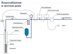
This scheme is discussed in this article: Tutorial. Do-it-yourself automatic water supply.
How to identify malfunctions of hydraulic accumulators in the automatic water supply system of a private house:
1.
Water began to flow in small portions. That is, there is repeated periodic spitting of water from the tap in small portions.
2.
The gauge needle jumps sharply up and drops to zero.
check the following first: Watching the pressure gauge, press the accumulator spool to release air. If the arrow on the pressure gauge goes down sharply, then there is very little air. Hold the spool and completely bleed all the air. If water comes out, the membrane is torn. If not, then the membrane is intact and the air has escaped through the slots or spool. What to do next will be described below.
How to identify malfunctions of accumulators in hot water supply:
1.
From safety valve, which is installed at the water heater, began to dig.
If these symptoms are present,
How to identify malfunctions of accumulators in the heating system:
1.
The pressure in the system has become unstable, the pressure rises and falls sharply. How much it rises and falls, alas, I will not tell you - it depends on many factors. Only experience will tell. From experience I can say that a well-tuned system should have an amplitude of no more than 0.6 bar. Less is better. This is for example from 1.4-2 bar. If you have more, you should be wary and check the operation of your accumulator. Perhaps the volume is not enough.
If this symptom is present, then check the following first: Press the spool button and bleed air for a fraction of a second. If there is no air, then the air has escaped somehow through the slots or spool. If water poured out, then the membrane is torn. If there is no water, then release the air to the end. If there is no air, and the water has not gone, then the membrane is intact. What to do next will be described below.
There is an opinion among the people that the air gradually leaves the accumulator, even if everything is sealed there. This may be due to some capillary reactions. Air can seep through: Even through metal and even rubber (I read it from chemistry, and many people talked about it). But in my experience, the life of a hydraulic accumulator can easily reach up to three years. There were cases from my practice: Already 4 years have passed since I installed a hydroaccumulator for water supply to my father, and at least henna for him. Serves great.
In cases where air has escaped (comes out)- Tighten the nut on the spool pin. And buy a metal car cap with a rubber gasket, which is sold in car dealerships. And after pumping in the air, screw the cap onto the pipe, which will not let the air out of the spool. About what to upload and how much to upload will be described below.
Inside the accumulator is a rubber membrane - this membrane looks something like this: 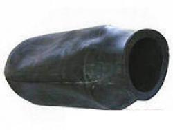
The membrane repeats the shape of the accumulator itself, which we see from the outside. Outside the membrane is the ordinary air we breathe. And water is poured inside the membrane. 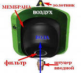
Some large hydraulic accumulators have the following membrane: 
Water enters the membrane from below, and the other outlet is designed to release air from water or coolant. Thus, large accumulators are equipped with two threaded connections (1/2-1): the lower one is for supplying liquid (water or coolant), the upper one is for air discharge. Do not confuse the pip with the spool from the air outlet thread. In this case, the spool pin is located from the bottom-side. Usually, an automatic air vent is screwed onto the upper thread to release air in automatic mode. But cases are not ruled out when liquid power is connected to the top, if the through diameter allows. When power is supplied from above, the air vent can be neglected. In this case, accumulations of fine crumbs, sand are possible if there is no filter.
Hydraulic accumulator in a simple way, people call names expansion tank. Therefore, a hydraulic accumulator and an expansion tank are synonymous, since by virtue of their life they perform one task.
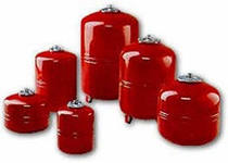
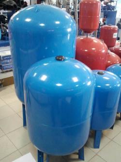
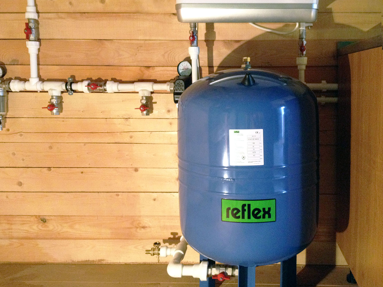
There are blue and red accumulators! So it was agreed that Blue colour treat water supply and cold water. And the red color refers to heating and hot water. There are also colorless accumulators on the market.
There is one more nuance: In blue hydroaccumulators food rubber is used, and manufacturers are trying to use safe rubber for human health in blue accumulators. Also in blue accumulators it is possible to change the membrane. But not always in red.
It is a big mistake to believe that the red accumulator withstands large temperature overloads (that is, withstand high temperatures). In our case, we can set up the system in such a way that hot water does not always reach the accumulator. System setup will be described below.
Changing the membrane in the accumulator is not at all troublesome. So if the membrane is torn, then it is still cheaper to buy the rubber membrane itself than to buy a hydraulic accumulator. To change the membrane, not at all tricky operations are needed: Unscrew all the bolts, pull out the old membrane and also install a new membrane. This is done one or two times. Tighten all bolts evenly. It is impossible to tighten only one bolt to the end, as the edge of the membrane may move and go inside, which will lead to smudges. Do not smear the joint with sealant, since it reduces friction between metal and rubber, and when tightened, the membrane will roll (slide) inward and form a loose connection and smudges will also occur.
Blue accumulators, almost always used for water supply and therefore they have an overestimated operating pressure threshold of up to 8 bar. And the reds have up to 5 Bar.
Where is a hydraulic accumulator used? The purpose of the hydraulic accumulator.
If we define it through the eyes of a physicist, then the accumulator is used where necessary:
1. Create an opportunity to accumulate a liquid medium in the form of an additional volume occupied in space. The space that changes depending on the deformation of the air in the accumulator.
2. Create an opportunity to reduce or balance hydrostatic pressure surges. That is, to reduce the effect of excess or decrease in pressure in enclosed space.
Its value as an element water supply and heating systems - to receive a liquid medium due to an increase in pressure and give it away due to a decrease.
Hence its purpose- Getting rid of pressure surges by releasing or increasing the volume of fluid in a confined space.
Its purpose, however, depends on the task being performed, which we will consider further.
Where to use the hydraulic accumulator?(From simple to complex).
1.
In the water supply system.
2.
In the heating system.
Parameters of hydraulic accumulators.
Each accumulator is equipped with two main parameters:
1. Working maximum pressure. On average, for water supply 6-8 atmospheres (bar). For heating 5 bar.
2. The volume of the accumulator. The accumulator itself, which we see from the outside, is this external form in terms of volume and is indicated in the passport or on the label. The liquid that the accumulator can take is much lower, maybe even half, depending on the pressure amplitude (the difference between the upper and lower pressure limits). The higher the difference, the more the battery can take.
Each hydraulic accumulator must be checked for the permissible value of the pressure of the pumped air. The accumulator has a spool valve like a car wheel. To check and set the required air pressure value, you will need a conventional car pump, which is pumped car wheel. Preferably with a pressure gauge that shows the pressure inside the tire. Automotive pump pressure gauges have the Pascal scale (Pa, MPa). That is, on the pressure gauge, the scale of 0.1 MPa will be equal to one atmosphere (1 Bar).
We will talk about how much air should be pumped in below.
Hydraulic accumulator in the water supply system.
If something is not clear about automatic water supply of a private house, then please read here: Tutorial. Do-it-yourself automatic water supply.
The hydraulic accumulator in the water supply system serves to accumulate water. To maintain constant pressure in the pipeline. In rare cases, on long sections of the pipeline to protect against water hammer.
Also, the blue accumulator must be installed on hot water supply. Where water is heated, water expands. And when the water expands, it begins to increase the pressure, which leads to the release of water from the safety valve. To prevent a strong increase in pressure, a hydraulic accumulator is installed.
Setting up a hydraulic accumulator for an automatic water supply system.
At automatic system water supply of a private house, where there is a pressure switch, which is set to certain thresholds of maximum and minimum pressure. In this case, the accumulator needs a pressure lower than the minimum lower pressure threshold by 2-3 meters (0.2-0.3 Bar). The minimum pressure of the relay can be found by observing the change in the arrow on the pressure gauge. That is, if the minimum pressure is 1.5 Bar, then the air pressure should be 1.2 Bar.
Setting order:
1. In cases where your accumulator is already connected to an automatic water supply system and there is water in it, then you must turn off the power to the system. Next, drain the water from the tap to pour out all the water in the system. Leave the faucet open. A situation may arise when there is water in your accumulator. And start pumping air through an automobile or other pump. During the pumping process, if water starts to run from the tap, this means that there is water in the accumulator. This symptom indicates the following: Or there was a depressurization of the air, and the air escaped through any cracks or through the spool; Or the membrane is broken. And if any symptom occurs, then it is necessary to stop pumping air. Next, close the tap and turn on the water supply system. Open the faucet and let the water pass 20 liters. Close the faucet. Next, go to the accumulator and press the spool until the air runs out. If water flows through the spool, this means that the membrane has torn. The membrane needs to be changed.
If there is no water, then everything is in order with the membrane. It is necessary to repeat the inflation process, to the desired pressure, which was described above.
After you have set the required air pressure in the accumulator, turn on the power and open the tap and let the water out. Go to the manometer and watch the arrow. The first time it drops to zero is not scary - this means that there was a little air in the accumulator and it came out. But the second time, when the arrow drops to zero, this means that the air pressure is greater than the minimum pressure of the relay. It is necessary to gradually bleed the air from the accumulator and check again. If possible, watch the water flow out of the faucet. Tap water must flow continuously.
There is a more professional way how to set the pressure in the accumulator.
Pump air into the accumulator, slightly more than the minimum pressure threshold of the relay. Then connect to the water supply system. Close the taps in the bathrooms and turn on the power. Let the accumulator fill up a little. Turn off pump power. And drain all the water from the accumulator from the tap - this will make it possible to get rid of unnecessary air in the system, which spoils the setting. Restart the pump supply to a pressure just above the minimum pressure switch threshold. Next, turn off the power to the pump. And slowly release the pressure through the valve to the required mark on the pressure gauge. And if the arrow is at the required value below the minimum threshold of the relay, then air is released from the accumulator, and as soon as the pressure drops on the pressure gauge, stop bleeding air from the accumulator. Since the arrow falls at the moment when the air pressure has become less than the pressure of the system and at this moment water begins to flow into the accumulator. And the setup is complete. Next, turn on the power and open the tap to release water, and observe the lower pressure threshold and if the arrow on the pressure gauge does not drop to zero, then everything is fine. If the arrow on the pressure gauge drops sharply to zero, then you need to bleed a little more air.
The choice of the volume of the hydraulic accumulator for the automatic system water supply of a private house is a very controversial issue. I can recommend purely economically - this is 80 liters. Not too much, not too little, and not too expensive. The ability to find a membrane for such a hydraulic accumulator. Doesn't take up much space.
For those who want to know how to assemble an automatic water supply with their own hands, go here: Tutorial. Do-it-yourself automatic water supply.
Setting up a hydraulic accumulator for hot water supply.
Information on how to connect electric water heater in the apartment.
For hot water supply, you can use blue accumulators. In addition, their operating pressure threshold is higher than that of red accumulators.
First, consider the diagrams where the accumulator is installed.
Scheme 1.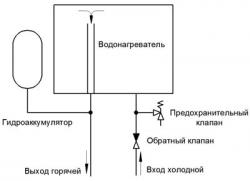
Scheme 2.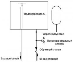
Scheme 1 helps to save more materials for connecting a hydraulic accumulator, and also helps to make assembly easier and more efficient. The difference between scheme 1 and scheme 2 is not significant. It is better to choose scheme 2, since cooler water will flow into the accumulator.
As for volume, then the volume for hot water supply is 5-10% of the volume of heated water. That is, if the volume of heated water is 300 liters, then the volume of the accumulator according to the passport will be 15-30 liters. It's a matter of taste, the more the better. If these are large volumes of heated water of 300-500 liters, then 5% is suitable. If small up to 100 liters, then 10% of the volume of heated water. For central water supply, it is better to use larger volumes of accumulators. Since the pressure there is very unstable and get under the right pressure very difficult. There is a big pressure difference.
Air pressure in accumulator for hot water supply. It’s also a difficult question, so far there are two directions in which you can navigate:
1. Average value between the minimum water supply pressure and the safety valve relief pressure. This is actually conditional. More is less, and the accumulator will still work, perhaps even for a long time. Usually the safety valve has 6 bar. Minimum pressure in central water supply approx. 2 bar. And that average is 4 bar.
2. Accurate pressure calculation. Accurate calculation helps to understand such factors as: the life of the membrane, obtaining the maximum efficiency of the accumulator.
To get the calculation, you need to identify the task or factors that affect these calculations.
The first factor: is to obtain maximum efficiency (Coefficient useful action).
Second factor: Getting long term hydraulic accumulator service.
Obtaining the maximum efficiency is expressed by obtaining the maximum accumulation of water in the accumulator. That is, to obtain such parameters that are able to accept as much water as possible during expansion.
The most basic problem of failure or operation of a hydraulic accumulator is the depressurization of two different media (Water and air). When the rubber membrane breaks, depressurization occurs. Also, there are cases when air escapes from the accumulator, thereby reducing the pressure in the accumulator, which leads to incorrect operation parameters of the accumulator. Often the spool begins to release air, and in order to exclude the influence of the spool, it is necessary to tighten the metal cap with a rubber gasket, which is sold in car dealerships. This cap prevents air from escaping through a faulty spool. You can also try to tighten the pipe nut. See image. 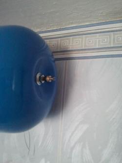
What causes a rubber membrane to break? The membrane breaks due to the banal wear of the rubber through the constant expansion, contraction and bending of the rubber. But there is one reason that greatly increases the wear of the rubber membrane, but more on that later...
There is an opinion that when there is not enough air in the accumulator, the membrane expands greatly, thereby greatly stretching the rubber, and ultimately leads to a rupture of the membrane. Seeing what membranes are in the accumulator, they are pushed to the idea that this cannot be, since the membranes themselves are large enough to expand to fill or repeat the entire external volume of the accumulator without causing strong stretch marks. That is, they are not particularly stretched there in order to tear themselves by stretching.
The main reason for the rapid wear of rubber, at least that's how it seems to me, you may think otherwise, but I will put it this way: This is when the accumulator quickly releases water. That is, water quickly leaves the accumulator as a result of a decrease or lack of pressure in the water supply system. When you open the tap to the fullest, the pressure in the water supply system decreases and the accumulator begins to release water, and as soon as the water in the membrane runs out, the membrane abruptly collapses into a flat sheet. The edges of the so-called sheet bend strongly. And than more difference pressure between air and water, the more destructive it is for the rubber membrane. In other words, reverse water hammer is obtained. Constant such a sharp or even slow folding of the membrane is very detrimental to rubber.
Of course, I do not argue with you, you can trust specialists who think differently. But how would you put it. Very, many people and professionals are still downloading great pressure into the accumulator, motivating this by not greatly expanding the membrane. Or even believing that the membrane should not expand at all, only in rare cases. That is, some experts, pumping up the accumulator strongly, suggest that there should not be expansions at all, and if expansions suddenly occur, they will be very rare phenomena. Thus, as if mistakenly believing that the rubber will be in constant rest (in the form of a rolled sheet) for a long time, thereby increasing the service life. Are they wrong?
The water in the accumulator constantly expands when heated, and will constantly disturb the accumulator.
Therefore, it is not advisable to have a membrane in the accumulator that goes into the state of a rolled sheet. This is detrimental to the membrane.
And so, the above proof - gives one identity - this is that the membrane should not, from case to case, fold into a sheet. And in order to prevent the membrane from folding into a sheet, it is necessary that the air pressure in the accumulator be less than the water pressure. As if the membrane in the accumulator must be constantly filled.
And in order to get the maximum efficiency of the accumulator, it is necessary that in a quiet mode there should be as little water in the accumulator as possible.
The exact calculation will be for an apartment: Inflate the accumulator with air to a pressure less than the minimum water pressure. That is, it is necessary, either by experience or by numbers from specialists, to find out what pressure is in your house, but it is better to find out what the minimum pressure is in your apartment. But consider one more fact! When you turn on the faucet in the kitchen or bathroom, the pressure drops - that's a fact! Therefore, subtract one more atmosphere from the minimum pressure and get the pressure that must be given to the air in the accumulator. The pressure will be less than the minimum water pressure by 1 Bar.
You can also check central water pressure on your own! There are some ways to check:
1.
Inflate the accumulator with air up to one atmosphere. Connect it to water. And in a moment the air pressure in the accumulator will be equal to the water pressure. And connect the pump to the accumulator and it will show you the pressure. After you know the pressure, it is necessary to turn off the water supply taps and lower the pressure of hot water supply to zero. And start pumping the desired pressure.
2.
The second method is suitable only if there is a tap between the accumulator and the water supply system. Pump up the accumulator to 4 atmospheres, connect it to the water. Open the tap - if water began to flow into the accumulator (Listen and you will hear), then the water pressure is above 4 atmospheres. If not, close the faucet. Release the air from the accumulator to 3 atmospheres. Open the faucet - and if the water gurgled (the sound of flowing water in the pipe). Water should flow for at least 3-5 seconds. You just do not confuse this murmur with filling the pipe leading to the accumulator. The second way requires a lot of experience or technical engineering thinking. It makes it possible to immediately set the pressure of the accumulator by bleeding air from the accumulator, without resorting to additional pumping.
Accurate calculation for a private house: Fill the accumulator with air to a pressure less than the minimum water pressure, by 1 bar. That is, if your minimum pressure on the pressure gauge shows 1.5 Bar, then the air pressure in the accumulator should be 0.5 Bar.
Setting up a hydroaccumulator for water heating.
Firstly, when pumping air into the accumulator, you need to disconnect it from the heating system. There must be no water in it.
We will not consider the scheme here, since any water system heating has an expansion tank or a hydraulic accumulator. The accumulator is connected to the central main return pipeline. Closer to the boiler or boiler room. But this does not mean that if you install it in another place, it will not work.
The main task of the accumulator in the water heating system- this is to extinguish pressure surges when the temperature of the coolant changes. In this task, a large permeability to the coolant accumulator is not required. It is even enough to connect the accumulator with a conventional flexible hose, which we connect the toilet bowl. But in some cases it is necessary to increase the diameter of the supply pipe to the accumulator: In cases of dirty rusty water, in order to exclude clogging and accumulation of sand in the pipe (20mm). And in cases where it is necessary to additionally protect the pipeline from water hammer. In this case, the diameter of the pipeline, must repeat main pipeline and should be connected as close as possible to main pipe.
In my experience, there have been cases when the hoses turned out to be not a reliable conductor of the coolant, since the material from which they are made was simply corroded by corrosion and the connection simply broke and cracked.
The size or volume of the accumulator for heating systems.
For heating a private house, use a red accumulator, especially for heating. Since it uses more technical rubber and can last longer. Blue hydraulic accumulators use food-grade rubber and manufacturers for this purpose may sacrifice the quality of rubber for the health of citizens.
I heard somewhere, and some sellers also said that if you take a deliberately large size of a hydraulic accumulator, then it will be worse than with a small volume of a hydraulic accumulator.
The basic rule is that the larger the volume of the accumulator, the better. With a large volume, pressure surges are less noticeable than with a small volume of a hydraulic accumulator.
But there is already an inveterate rule, and it justifies the economic factor. This is 10% of the total volume of the coolant (water).
How to calculate the volume of coolant for your home?
Multiply the number of sections of the most common radiator by 0.3 liters and add 10-20% of the supply pipe to the answer, depending on the scheme. If there are underfloor heating, then add 0.2 liters for each square of underfloor heating. (This is a simplified version of the calculation. Accuracy is conditional, statistical).
Setting up a hydroaccumulator for heating.
To calculate what pressure should be pumped into the accumulator, you need to know:
1. The height of the highest point of the heating system or radiator from the horizon itself expansion tank. For a three-story building with a basement, let's say 9 meters.
2. The minimum shutdown threshold for your boiler. If you have complex electrical heating equipment (boiler), then it may have a boiler shutdown threshold at minimum pressure. This protection is designed to prevent the boiler from running without water. And if the pressure is low, then perhaps there may be no water. This threshold is usually 0.5 bar.
Option 1. Do you have an ancient boiler or works at any pressure. In this case, the pressure of the injected air in the accumulator must be equal to the height (From the accumulator to the upper radiator). If we have 9 meters, then translated into Bar, it will be 0.9 bar or 0.09 MPa. But keep in mind that the average pressure in the heating system will definitely be higher. Next, you need cold water set the pressure to about 3-4 meters more than 0.9 bar - this is equal to 1.3 bar. And leave it at that pressure.
Turn on the heating and warm up the system to 60 degrees and remember the pressure that happened at 60 degrees. And if at this temperature the pressure has become less, then add the coolant to the required value, which you remember. If you do not add pressure, then when the coolant cools down, a situation will arise when the pressure will drop sharply after 0.9 bar. Since at this pressure there is no coolant in the accumulator and the water will decrease sharply. Thus, the required pressure may not be in the upper radiators.
To prove this calculation, I will tell you about what:
Why is it necessary to pump 9 meters of air pressure? The fact is that if the pressure in the system is less than 9 meters, then our water simply will not rise to the upper radiators and will not fill them. Therefore, the pressure in the system must always be greater than 9 meters (0.9 bar). And a hydraulic accumulator pumped up to the maximum in its original position has less coolant inside it. And therefore, an inflated accumulator with such parameters will take more coolant during expansion. As a result, we can safely say that we use our accumulator with maximum efficiency. That is, with maximum potential.
By the way, for those who do not know, I explain: 1 bar of pressure raises a column of water by 10 meters in height.
Option 2. Cottage with basement (height 3 meters). But our boiler turns off at a pressure of less than 0.5 bar. In this case, we can ignore the height of the top radiators. And feel free to pump air into the accumulator to a pressure slightly less than 0.5 bar. Let's pump up 0.4 Bar. In this case, you can safely set the pressure cold water in the system up to 1 bar. And don't add more. Then do not forget to note what pressure will be with heated water up to 60 degrees. If it exceeds 1.5 bar, then it is better to reduce for one floor. In general, I recommend using low pressure, if possible, but within limits, so that the pressure does not drop much when the coolant cools down.
As proof of the second option, I'll tell you what:
Very often I encountered, and I'm not the only one, with such a phenomenon that you come as a lady and find that the boiler is not working. There are many reasons, maybe smudges somewhere. Or maybe the electricity was turned off and all the water in the system cooled down and this, NOTE, reduced the pressure in the system and the pressure went beyond the threshold for switching on the boiler. And the boiler, after they gave electricity, did not turn on and did not work! Therefore, it is necessary to take into account a smooth decrease in pressure to 0.4 bar. So that when there is a power outage, the pressure does not reach the critical pressure.
Option 3. Three-storey house with a basement (Height 9 meters) and a boiler with a shutdown threshold of 0.5 bar. In this case, we can use as the first option described above. Since when the water rises up to 9 meters, the boiler will have a pressure of 0.9 bar. Even if there are big leaks. The difference between 0.5 and 0.9 bar is 0.4 bar - that's 4 meters. Can you imagine how much water should pour out, this is 4 meters, this is almost the entire floor with all the radiators (30 liters). And only after that, the pressure at the boiler will drop to critical and the boiler will turn off. For the third option, inflate the accumulator with air to 0.9 bar. Set the pressure in the cold water system to 1.3 bar. The pressure in the system will increase when the water is heated. Remember the pressure when the coolant is heated so that when the coolant is heated, the pressure is set correctly.
If you leave the house for several days, it is better to have high blood pressure. Since over time, the pressure drops due to the release of gases. In the future, you will understand for yourself how much you need to add to check the heating once a month. It is possible to overestimate the pressure up to 2.5 bar with a well-heated coolant. If you often have to add pressure, then you should think about whether everything is in order with your accumulator. If everything is in order with the accumulator, then you should think about increasing the volume of the accumulator. With an increase in the volume of the accumulator in the heating system, you can add another accumulator and there will be two of them. This makes it possible to save on the purchase of a hydraulic accumulator.
Option 4. If this is a one-story building and the boiler does not have shutdown thresholds. In this case, it is generally possible to pump up the accumulator up to 0.1 bar, and pump cold water into the system up to 0.4 bar.
By the way, keep in mind that new advanced boilers have built-in hydraulic accumulators.
As for the professional adjustment of the accumulator for heating. It is necessary from the beginning to pump in obviously high air pressure. Connect it to the heating system. Set the required value in the heating system, to which the accumulator should be set. After we have set it up, we release air from the spool and observe the pressure gauge in the heating system. As soon as the pressure gauge needle deviates (the value has decreased), we stop venting air. Screw on the cap and you're done.
Hydraulic accumulators
General information
A hydraulic accumulator is a water tank with an elastic membrane, in one part of which there is water, in the other - compressed air. Designed to store a certain amount of water under pressure. It is the accumulator that provides pressure in the water supply system when the pump is turned off. The hydraulic accumulator consists of:
- Corps
- rubber membrane
- flange
- Nipples for pumping and bleeding air into cavity B (6)
- Air bleed nipples cavity A (7)
The principle of operation of a hydraulic accumulator is very simple. Initially, dry air is pumped into cavity B of the accumulator, usually at a pressure of 1.5 atm. Water from the main threaded connection enters cavity A, filling it. The air in cavity B is compressed and the pressure rises. Thus, both air and water are always in working condition in the accumulator, which are separated from each other by a diaphragm made of food grade rubber. Over time, the air pressure in cavity B may decrease. During normal operation, once a year, it is necessary to check the air pressure in the accumulator in the absence of water in cavity A. If the pressure is less than normal, then it can be pumped up using a conventional automobile pump through the nipple.
It should be noted that the accumulator is never completely filled with water. The actual volume of water in it depends on many parameters. For example, from the initial air pressure in the accumulator, the upper and lower preset thresholds of the pressure switch in the system, the elasticity and geometric shape of the diaphragm, the shape of the accumulator. To obtain the volume of water issued by the accumulator, you can use the following formula:
Vga = Vo x α x β
Where
Vga - the volume of water produced by the accumulator, liter
Vo - full overall volume of the hydraulic accumulator, liter
α - coefficient of initial data
β is the reduced elasticity coefficient of the membrane.
The given coefficient of elasticity of the membrane b depends on its shape, the material of the membrane, the shape of the accumulator and other parameters. On average, for calculations of individual water supply systems, it can be taken equal to 0.8.
Table of coefficients of initial data α
Using the above table and formula, you can get the desired value of the volume of water issued by the accumulator. For example, with Po = 1.5 bar, Pmin = 2.0 bar and Pmax = 3.0 bar, the hydraulic accumulator of the water supply system with an overall volume of 24 liters is capable of delivering:
Vha \u003d Vo x α x β \u003d 24 x 0.25 x 0.8 \u003d 4.2 liters.
|
||||||||||||||||||||||||||||||||||||||||||||||||||||||||||||||||||||||||||||||
What type of hydraulic accumulator to choose?
Hydraulic accumulators are vertical and horizontal. The name fully characterizes the way they are installed. Which one to choose if the dimensions of your room allow you to use both types. Here we would recommend to pay attention to the method of removing the accumulated air inside the rubber membrane. The fact is that in water supply systems there is always dissolved air in the water. Over time, during operation of the system, this air is released from the water and accumulates in various places, forming air pockets. One of these places is the cavity A of the accumulator. To remove this air, as well as air locks that occur during installation and repair of the system, an additional nipple is provided in the design of large accumulators (100 or more liters), through which the air accumulated in the system is periodically bled. When using a vertical accumulator with a capacity of more than 100 liters, air accumulates in the upper part and can be removed using this air release valve.
In horizontal accumulators, air can be removed using an additional section of the pipeline, consisting of an outlet air nipple, ball valve and drain into the sewer. At the same time, the accumulated air should be bled periodically once a month. Small volume accumulators are not equipped with an air bleed nipple. Therefore, the choice of their type is carried out exclusively by the convenience of the layout in your room. The removal of accumulated air in them is carried out by periodic complete emptying. To do this, an additional ball valve can be provided in the pipeline scheme. In addition, it is possible to remove air from systems with a small accumulator simply by periodically (once a week) turning off the power supply to the installation and bleeding the accumulated air through a washbasin or shower tap or other draw-off point closest to the accumulator. However, for greater efficiency this procedure should be repeated several times. That is, turn off the power to the pump, open the cold water tap, drain the water completely, close the tap and turn on the power to the pump. And so two or three times in a row.
How to choose the size of the accumulator?
Correct selection hydraulic accumulators for individual water supply systems is quite complicated. There is a large amount of input data that needs to be taken into account. In addition to the traditional shower and faucet in the kitchen, modern houses can be equipped with a bathtub, bidet, sewerage, washing machine and other equipment that requires water to operate. In addition to equipment, the number of people in the house can be different. These are objective factors, but when choosing the size of a hydraulic accumulator, subjective factors also have to be taken into account. For example, how many times per hour can you turn on the pump and fill the accumulator? What happens if several people use water at once? What will happen if it works at this time washing machine?
It should be noted that up to now, in our opinion, there have been no methods for choosing the size of hydraulic accumulators in Russia. Firstly, because in Russia there were no individual water supply systems. Secondly, people's requirements for such systems are too different. We offer you a method for selecting the volume of a hydraulic accumulator, which is based on the international calculation method UNI 9182.
Let's start with the fact that if you only have a water faucet, a shower and a watering faucet in your house, then you don't need to count anything. You need standard installation water supply with a hydraulic accumulator of 24 liters. Feel free to buy it. It is optimal in cases where the number of permanent residents in the house is up to four people. Even if you need to increase the number of water taps in the future, you can simply buy separately and install another 24-liter hydraulic accumulator at any point in the water supply system.
If you have a house without a sewerage system, but with more than three water points, then in any case a 50-liter hydraulic accumulator is enough for you.
The calculation method is intended for individual houses equipped with a sewerage system (septic tank), with bathtubs and other equipment that consumes a significant amount of water.
1. Determine the total water consumption coefficient Su. To do this, make a list of points of analysis in your home and indicate the number of each type of equipment.
2. Fill in table 1. Its second column is a table of coefficients for the frequency of use of each type of equipment (Cx). In the third column, enter the number of devices of each type of equipment in your home (n). In the right column of the table, multiply the Cx value by n. Sum the values of this column. You will get the total water consumption coefficient of your house.
Table 1. Determination of the total consumption coefficient Su
3. Depending on the obtained value of the total coefficient Su, determine the value of the maximum water flow required for your home. These values are presented in table 2.
For example, if you have a toilet, a shower, a faucet in the sink, a faucet in the kitchen (one for each device), then your consumption coefficient is Su = 3+2+6+2=13. The nearest Su value in the table is 12, therefore, for the normal functioning of the water supply system at home, you need to ensure maximum flow about 36 liters per minute.
4. To determine the volume of the accumulator, it is necessary to decide how many times per hour (a) it is allowed to turn on the accumulator at maximum consumption intensity. Normal is 10-15 times per hour. It is also required to assign thresholds for the pressure switch of the water supply station (Рmin and Рmax). Lower threshold Рmin for two-storey houses usually equal to 1.5 bar, and the upper threshold Pmax - 3 bar.
Then, to determine the volume of the accumulator, you must use the following formula:
Where V is the total volume of the accumulator (liter),
Qmax - the maximum value of the required water flow (liter / min),
a is the number of system starts per hour,
Pmin - lower pressure threshold when the pump is turned on (bar),
Pmax - upper pressure threshold when the pump is turned off (bar),
Po - initial gas pressure in the accumulator (bar).
Calculation of air pressure in the accumulator
What initial air pressure should be in the accumulator? If you installed a hydraulic accumulator in the basement, then its minimum value is easy to calculate. You need to take the height in meters from the basement to the top point of your water supply system. For example, for two-story house this is 6-7 meters, three-story - about 10 meters, then add 6 to this value and divide by 10. You will get the required value in atmospheres. For example, for a two-story house 7 + 6 = 13 / 10 = 1.3 atmospheres. This is the minimum air pressure in the accumulator. Otherwise, water from it will not flow to the second floor of your house. However, these values \u200b\u200bshould not be overestimated, otherwise there will simply be no water in the accumulator. Usually the manufacturer himself sets the air pressure in the amount of 1.5 atm., but it may happen that the air pressure in the accumulator you purchased will be different. You should initially check it with an ordinary pressure gauge, connecting it to the accumulator nipple and, if necessary, increase it using a car pump.
The difference between the operation thresholds Рmax - Рmin determines the volume of water supplied by the hydraulic accumulator of the water supply system. The greater this difference, the more more efficient work accumulator, but the membrane in this case is loaded more and may burst.
The Pmin value (pump start pressure) is determined based on the hydrostatic pressure (water height) in your home's water supply system. For example, if the height of the pipes in your system is 10 meters, then the pressure of the water column will be 10 meters, which is equal to a pressure of 1 bar.
What should be the minimum pressure Pmin? The air pressure in the counter pressure chamber of the accumulator must be equal to the hydrostatic pressure, that is, in our case 1 bar. The lower threshold Pmin should then be slightly higher (by 0.1 bar) than the air pressure in the accumulator.
However, we need the system to work stably. The most critical, in terms of stability, is the highest point of analysis (for example, a faucet or shower on the top floor). The valve works normally if the pressure drop in it is at least 0.5 bar.
Therefore, the pressure must be 0.5 bar plus the hydrostatic pressure of that point. Thus, the minimum value of the gas pressure in the accumulator is 0.5 bar plus the value of the reduced hydrostatic pressure at the location of the accumulator (height distance between the upper point of analysis and the location of the accumulator). In our case, if the accumulator is located at the lowest point of the water supply system, then the minimum gas value in it should be set to 1 bar + 0.5 bar = 1.5 bar, and the threshold for operating (turning on) the pump Pmin = 1.5 + 0.1 = 1.6 bar. If the accumulator is located at the upper point, and the pressure sensor is at the lower point of the system, then the gas pressure in the accumulator should be set to 0.5 bar, and the pump activation threshold Pmin = 1.6 bar.
When assigning an upper threshold for the operation of an automatic water supply system, several points must be taken into account, first of all, the pressure characteristic of the pump. The value of the pressure generated by the pump in meters of water column, divided by 10, will show the maximum pressure value. However, it is necessary to take into account:
|
||||||||||||||||||||||||||||||||||||||||||||
- the pump characteristics indicate the maximum parameters without taking into account the hydraulic resistance of the pipelines
- voltage in electrical network often does not correspond to the nominal 220 V
- at maximum head values, the pump flow is minimal and your system will fill up for a very long time
- The performance of the pump decreases with prolonged use.
However, the initial moment in determining the upper threshold is the height of your house, or rather, the height of the water supply system. To determine the upper threshold value, add 20 meters to the height of your plumbing system and divide by 10. You will get the upper threshold pressure in bar.
Often you have to deal with the frequent turning on and off of the water supply pump with self-made water supply, and an additional stabilizer is also required to avoid problems during water hammer and power outages. It is the hydroaccumulator that will allow you to avoid all of the above.
What is a hydraulic tank for water supply systems
Arranged hydraulic storage tank easy enough. From the outside, it resembles the most ordinary tank, in which there is a horizontal or vertical variation of the layout, which is installed in a specially designated place. This container is connected to a pump for supplying water, as well as to a relay that regulates the pressure inside the pipeline.
Equipment:
- Working tank with specific volume.
- Elastic inner container, for the manufacture of which high-strength butyl rubber is used. It is placed inside the tank and must be securely sealed.
- A pneumatic valve is installed on the elastic container, due to which the change in the pressure of the water that is pumped inside is controlled.
- It is mandatory to have a safety valve, due to which the level of the limit value of air pressure is regulated.
- The threaded connecting pipe is responsible for the flow of water into the tank of the accumulator.
- Equally important is the presence of a connecting bracket, due to which the product is mounted.
A typical battery is installed in a private house, which is excellent for functioning in a drinking supply network, in which a number of specific elements are present. The accumulator tank can be additionally equipped with a pressure gauge, connecting pipes and a valve to manually release the pressure.
Including it has a significant difference from the expansion tank. The pressure and temperature levels are completely different, which can affect such performance characteristics as service life, reliability, proper functioning, product integrity, since in some cases the tank simply breaks. To be more precise, the elastic membrane can be damaged.
The device of the accumulator and its components
To start the operation of the device, it is required to immerse the pump (and it can be submersible or surface type) in water, while maintaining a specific pressure level supplied to the elastic membrane tank.
Hydraulic tanks have a certain principle of operation, however, the design will function correctly if:
- Installation instructions were used;
- Everything is carefully sealed;
- The product fully complies with GOST standard in terms of its quality.
There is an expansion of the capacity and an increase in the pressure of the air located in the space between the cavity of the membrane and inside tank body. An increase in pressure helps to turn off the relay, due to which the pump operates, and at this time water flows through the distribution points installed in the house.
According to how quickly the fluid flow is carried out, it decreases in the membrane cavity.
This means that the air pressure is reduced, and the relay turns on again for a set, but this happens at a certain level set by the manufacturer. After switching on, the cycle is repeated again until the next blocking of the pump.
Hydroaccumulator tank for cold water supply: classification
The device for controlling the supply of cold water, the operation of which is considered quite simple, may differ according to some criteria, so when buying, you need to pay attention to a number of features.
The volume of the container can be (l):
- even at 400.
A large tank is needed exclusively for industry, and in living conditions it is quite rare to find it. The configuration may be different, depending on what type of installation will be, in particular, horizontal or vertical. There are no special differences and advantages between them, since both options are compact in size, but there is a difference in the complexity of the installation process and no more.
The body material may differ, as there are tanks made of of stainless steel, however, their cost is much higher than cheaper models made from the most common steel sheet and enameled.
Tanks differ in the way in which air is bled off during periodic monitoring of the pressure in the cavity of the device body. To do this, a valve of the usual type or a banal tap can be installed. The latter option is most often installed in a hydraulic accumulator designed for a large amount of water. If you want to install a pressure pump, you need to be as careful as possible in the process of choosing it, since the device must be certified and have the necessary documentation for compliance with the GOST standard.
Optimum pressure in the accumulator for 100 and 200 liters
It is worth noting that the air pressure in the accumulator will affect how well it works, however, before installing a hydropneumatic tank for a water supply system, it is advisable to select a device according to its size and other nuances.
When choosing, you need to take into account again a number of features:
- How much water is consumed per day, as this will affect the capabilities of the pump for supplying water, and the selection of each part must be carried out at the same time, to eliminate discrepancies in the connectors.
- What pressure will the energy accumulator maintain in the water supply network? This will be affected by the power of the equipment, as well as how durable the case is. For example, cheap pressure stations do not exceed a pressure of 2 atm, which at some points can lead to a malfunction.
- The size also depends on which pump will be submersible or surface. For example, with a submersible version, the location of the hydraulic pump at the outlet is necessary, which will prevent additional and unauthorized switching on and off. If the pump is of a surface type, then the installation of a hydraulic accumulator should be carried out in close proximity to it. The higher it is located, the smaller the design can be chosen by volume. A surface pump is installed on a much smaller tank than a submersible one.
Whether present or absent check valve in the cavity of the water supply system inside the house, the pressure also depends. For example, in the absence of such a valve, the hydraulic tank is mounted in front of the place where the tee is installed in the water supply circuit, and a pressure gauge is required. By technical security it is permissible to turn on and off the pump per hour no more than 25 times, which will eliminate the occurrence of breakdown and repair.
The principle of operation of the accumulator in the water supply system and its capacity
When supplying the water supply system with automation, you must first check it for leaks and malfunctions, and if any, then establish the causes of their occurrence, which will allow for more competent maintenance. It is worth noting that some prefer to install a homemade hydropneumatic receiver.
However, assembling it with your own hands, you need:
- Strict observance of technology;
- Compliance with recommendations from experts;
- Use of only quality materials.
In this case, you should not pay attention to such moments as, for example, what color is the tank, blue or red. After collection, you need to full review design for identifying problems, on which its validity period directly depends. As for the capacity of the tank in the accumulator, it directly depends on how many points water enters the house.
For example, for a family of 2 people, 50 liters is enough, but for 3 or more - 150 or 200 liters.
Choosing the types of tank by capacity, you need to immediately decide on the location. During installation vertical view, it is required to add a third of the volume to the design pressure value, due to which the pump will turn on much less often. However, it is worth considering the moment that the room where the equipment will be installed must be warm and without sudden changes in temperature, which can lead to damage to the device.
Hydraulic accumulator for water: installation
As already noted, accumulators are considered not particularly suitable for heating and hot water supply. In addition, it is worth considering that with improper installation, even problems can arise.
Why and which tank has problems:
- It is impossible to drain the water, as the drain is airy;
- After the pump stops, the water goes back to the source;
- The tank fills up a little;
- The nipple starts to leak;
- The pump does not hold pressure, and it drops sharply, and not gradually;
- Downloading is very slow and the like.
![]()
All these malfunctions are associated with an illiterate installation. In order to be sure that the entire system is working after assembly or purchase and subsequent installation, it is worth testing. It is necessary to check the integrity of the structure and connections. Using a car pressure gauge, the pressure inside the tank is measured. Connection is made to the outlet in the pump and the hole in the water supply system, with additional installation safety valve.
It is required to pump water into the accumulator, and then the mandatory setting of the relay follows.
The capacity of the accumulator will be filled with water, and gradually, so that there is no rupture of the membrane. At this point, you need to carefully monitor the data on the pressure gauge and control the correct installation and operation of the relay. The pump is turned on and the pressure is monitored, which should decrease by no more than 10% at start-up. It is advisable to carry out a check for the purpose of prevention general condition devices once a month, which will help to find problem areas in the equipment as quickly as possible, and eliminate them at the initial stage of failure.
How a hydraulic accumulator works (video)
Experts recommend when buying a hydraulic tank to pay attention to the popularity rating of products, and not to take too cheap designs. And also for installation, hire professional craftsmen, which will eliminate installation problems and provide warranty service.


