Send your good work in the knowledge base is simple. Use the form below
Students, graduate students, young scientists who use the knowledge base in their studies and work will be very grateful to you.
Hosted at http://www.allbest.ru/
Introduction
The heat consumption of industrial enterprises makes up a large part of the total heat consumption. Every year the share of centralized heat supply of industrial enterprises from thermal power plants is growing, which makes it possible to eliminate a large number of industrial boilers and thereby reduce air pollution by emissions of combustion products.
Industrial enterprises receive steam for technological needs and hot water both for technology and for heating and ventilation. Of great importance are heating networks, steam and water, through which steam and hot water are transported to consumers. The process steam condensate return system at the CHPP is also extremely important. The production of heat for industrial enterprises requires large amounts of fuel burned in the furnaces of steam generators of combined heat and power plants and boiler houses.
For CHP and boiler houses, network districts, improving the quality of labor means achieving defect-free work. To do this, it is necessary to carry out a whole system of measures, which include advanced training, personnel training, and a system of preventive repairs.
The efficiency of production is ensured by its high technical and economic indicators, among which the most important are the specific fuel consumption for the supplied heat and electricity.
Thermal consumption is the use of thermal energy for a variety of domestic and industrial purposes (heating, ventilation, air conditioning, showers, baths, laundries, various technological heat-using installations, etc.).
When designing and operating heat supply systems, the following must be taken into account: a) type of heat carrier (water or steam); b) coolant parameters (temperature and pressure); c) maximum hourly heat consumption; d) change in heat consumption during the day (daily schedule); e) annual heat consumption; f) change in heat consumption during the year (annual schedule); g) the nature of the use of the coolant by consumers (direct intake from the heating network or only heat extraction).
Heat consumers present to the heat supply system different requirements. Despite this, heat supply must be reliable, economical and satisfy all heat consumers in a quality manner.
Heat consumers can be divided into two groups: a) seasonal consumers; b) year-round consumers.
Seasonal consumers use heat not all year round, but only during some part of it (season), while the heat consumption and its change in time depend mainly on climatic conditions (outdoor temperature, solar radiation, wind speed and direction, air humidity). The main value is the temperature of the outside air; the influence of other climatic factors on heat consumption is often neglected.
Seasonal consumers of heat are: a) heating; b) ventilation (with air heating in heaters); c) air conditioning (obtaining air of a certain quality, purity, temperature and humidity).
Year-round consumers use heat throughout the year. This group includes: a) technological consumers of heat; b) hot water supply for household consumers.
If for seasonal consumers the heat consumption practically depends on one factor - the outside air temperature, then for year-round consumers - on many different factors. Thus, the technological consumption of heat depends on the production technology, the type of products produced, the type of equipment, the mode of operation of the enterprise, etc. Climatic conditions have very little effect on the heat consumption of year-round consumers.
Year-round consumers provide the most economical operation of the CHPP throughout the year, while seasonal load due to its uneven annual schedule and especially in view of the presence of a summer dip leads to a decrease in the efficiency of the CHP.
The further development of hot water supply, air conditioning and refrigeration planned in our country will not only further improve living conditions population, but will also have a positive effect on the efficiency of heat supply systems.
1. Schedule of central quality regulation
One of the main ways to control heat supply by a source of district heating is to generate heat with optimal, economically most profitable parameters (qualitative regulation of heat supply). To determine such optimal parameters coolant, a temperature graph is plotted.
The construction of the graph is based on determining the dependence of the temperature of network water in the supply and return lines on the temperature of the outside air.
Calculation of coolant temperatures in the supply and return lines of the heating network at various temperatures outdoor air is carried out according to the formulas:
where t v.r - the estimated air temperature inside the room, about C, we accept according to Appendix 3
Dt - temperature difference of the heating device, o C
where f e is the calculated temperature of the water entering the heating devices (after mixing in the elevator), o C, equal to
where a is the mixing coefficient equal to the ratio of the amount of return water mixed by the elevator to the amount of water coming from the heating network (assumed a = 1 ... 2.5)
Df - estimated water temperature difference in a warm network at an external heating temperature, o C:
Df \u003d f p? f about \u003d 140? 70 \u003d 70
and - estimated temperature difference in the local heating system, o C
i \u003d f e -f o \u003d 93.33-70 \u003d 23.33
t n.o - design outdoor air temperature for heating design, o C, determined according to table 1.3 for Kazan, t n.o =? 29.
t? n - accepted arbitrary values of outdoor air temperatures in the temperature range from t n.o to t v.r, o C
Att? n= t But= ? -29 OWITH
Further calculation is carried out similarly, setting the outdoor air temperatures t? n \u003d -12, -10, -8, ..., +8 o C. We summarize the calculation in table 1.
Table 1 - Construction of the CCR schedule
Based on the data obtained, we build a schedule of central quality regulation.
2. Determination of the calculated heat consumption
To determine the estimated heat costs, we will compile a table of characteristics of buildings that are part of an industrial enterprise for which a heat supply system is being designed.
Table 2 - Characteristics of buildings
|
Designation |
Purpose of the building |
t w.r. , o C |
Specific characteristic, W / (m 3 K) |
Quantity, pcs |
Internal heat generation, kW |
Steam consumption, t/h |
||||
|
heating, q o |
ventilation, q in |
wash basins |
||||||||
|
Administrative |
||||||||||
|
Dining room |
||||||||||
|
machine shop |
||||||||||
|
machine shop |
||||||||||
|
Repair shop |
We determine the calculated heating load Q o, W
Q o \u003d q o V (t v.r? t n.o), (5)
where q o - specific heating characteristic buildings, W / (m 3 K);
V - construction volume of the building according to the external measurement, m 3.
t v.r - design air temperature, indoors, o C;
t n.o - outdoor air temperature for heating design, o С
Q A o. max \u003d 0.298 18750 (18 + 29) \u003d 262612.5
Q B o. max \u003d 0.45 8000 (16 + 29) \u003d 162000
Q 3 about. max \u003d 0.448 37500 (16 + 29) \u003d 756000
Q max \u003d 0.448 37500 (16 + 29) \u003d 756000
Q And about. max \u003d 0.38 50000 (18 + 29) \u003d 893000
The main task of heating is to maintain the temperature of the premises at a given level. To do this, it is necessary to maintain a balance between the heat losses of the building and the heat gain. Thus, when determining the estimated heat consumption for heating industrial buildings it is necessary to take into account the amount of internal heat generation from the process equipment of workshops, which are quite stable and often represent a significant proportion of the calculated heating load, as well as infiltration losses reaching 25-30% of heat loss through external fences. Hence,
Q? O. max =m Q o . max - Q ext, (6)
where m is the infiltration coefficient; for public buildings take m=1, for industrial buildings m=1.25…1.3;
Q ext? internal heat generation, W;
Q? And about. max=1 262612.5=262612.5
Q? b o. max=1 162000-90000=72000
Q? Z o. max=1.3 756000=982800
Q? s o. max=1.3 756000=982800
Q? and about. max=1.3 893000=1160900
Q in. max \u003d q in V (t v.r?t n.v), (7)
where q in - specific heat consumption for ventilation, W / (m 3 K);
t n.v? estimated outdoor air temperature for ventilation design, o C; for Kazan according to table 1.3 t present \u003d -18 o C
To reduce the calculated heat consumption for ventilation, the minimum outdoor temperature, which is used to calculate ventilation units, t n.v. is taken, as a rule, higher than the calculated temperature for heating t n.d. According to current standards, the design outdoor air temperature for ventilation design is defined as the average temperature of the coldest period, which is 15% of the duration of the entire heating period. The only exceptions are industrial workshops with a large emission of hazards, for which t n.v. taken equal to t n.o (such shops include iron foundry, steel foundry, thermal, forge, copper foundry, metal coating shop)
Q A c. max \u003d 0.113 18750 (18 + 18) \u003d 76275
Q b c. max =0.8 8000 (16+18)=217600
Q max \u003d 0.15 37500 (16 + 18) \u003d 191250
Q max \u003d 0.15 37500 (16 + 18) \u003d 191250
Q and c. max =0.1 50000 (18+18)=180000
where 1.2 is a coefficient that takes into account cooling hot water in subscriber systems of hot water supply;
m - the number of showers, pcs;
a - the rate of consumption of hot water in the shower, a \u003d 60 l / person;
t cm1 - temperature of the mixture of hot and cold water in the shower t cm1 \u003d 37 ° C;
t x.v - cold temperature tap water t x.v =5 about C;
n - number of washbasins, pcs;
b - hot water consumption rate for the washbasin, b=5 l/h;
t cm2 - temperature of the mixture of hot and cold water in the washbasin t cm2 =35 o C;
c p is the heat capacity of water c p = 4.19 kJ/(kg K);
All calculations of thermal loads are summarized in table 3
Table 3 - Estimated thermal loads of the enterprise
|
Designation |
Purpose of buildings |
||||||
|
Administrative |
|||||||
|
Dining room |
|||||||
|
machine shop |
|||||||
|
machine shop |
|||||||
|
Repair shop |
|||||||
3. Plotting heat consumption graphs
The graph of heat consumption for certain types of heat consumption and the total graph of heat consumption are built on three points corresponding to three average daily outdoor temperatures: t n, t n.v and t n.o.
At the same time, it should be taken into account that in buildings with internal heat release, the beginning heating season occurs at a lower temperature t n, o C
To determine the missing heat loads for heating and ventilation, the following formulas for recalculating heat loads are used:
The calculation is carried out separately for each building for outdoor temperatures of +8 o C, +5.2 o C, +4.65 o C, 0 o C, -2 o C, -14 o C, followed by summation by load type.
The calculation results are summarized in Table 4.
Table 4 - Calculation of loads for plotting heat consumption
|
Designation |
Purpose of buildings |
Heat consumption, W |
||||||||
|
Administrative |
||||||||||
|
Dining room |
||||||||||
|
machine shop |
||||||||||
|
machine shop |
||||||||||
|
Repair shop |
||||||||||
|
for all buildings |
||||||||||
The heat load on hot water supply is year-round, during the heating period it is conditionally assumed to be constant, independent of the outside temperature. Therefore, the graph of heat consumption for hot water supply is a straight line parallel to the x-axis.
In the summer period (the range of standing time t n from n about to n = 8400 h) there are no heat loads for heating and ventilation, the load on hot water supply will be 80% of the winter load on hot water supply
The right side of the graph represents the dependence of the total heat load corresponding to certain average daily outdoor temperatures (from the left side of the graph) on the duration of these temperatures (the number of hours during the heating period with average daily outdoor temperatures equal to or below the data).
To build the right side of the graph, we determine the duration of standing temperatures for Kazan
Table 5 - Duration of standing outdoor temperatures
Based on the data obtained, we build an annual heat consumption graph for the duration of heat loads.
4. Determination of the estimated costs of network water
heat network water heating
The estimated costs of network water are determined separately for each type of load
Estimated consumption of network water for heating G o, kg / s
where f p, f o - the temperature of the network water in the supply and return pipelines at a temperature t n.o;
с - heat capacity of water, kJ/(kg K)
Estimated consumption of network water for ventilation G in, kg / s
where is f? p, f? o - temperature of network water in the supply and return pipelines at a temperature t n.v (except for buildings C, D, D, E, N, P for which the estimated costs of network water are calculated at a temperature t n.o), we determine from the schedule of the TsKR vacation warmth
Estimated consumption of network water for hot water supply G hw, kg / s
where is f? p, f? o - temperature of network water in the supply and return pipelines at a temperature t n.i; determined from the schedule of the CCR heat supply
The estimated costs of network water for each building are summarized in Table 6.
Table 6 - Estimated consumption of network water
|
Designation |
Purpose of buildings |
|||||
|
Administrative |
||||||
|
Dining room |
||||||
|
machine shop |
||||||
|
machine shop |
||||||
|
Repair shop |
||||||
To plot the consumption of network water, except for the calculated ones, i.e. maximum, the same formulas are used to determine other characteristic values of network water flow rates.
We present the calculation in table 7
Table 7 - Consumption of network water depending on t outside air
|
Designation |
Purpose of buildings |
Network water consumption, kg/s |
||||||||
|
Administrative |
||||||||||
|
Dining room |
||||||||||
|
machine shop |
||||||||||
|
machine shop |
||||||||||
|
Repair shop |
||||||||||
|
for all buildings |
||||||||||
Based on the obtained data, we build graphs of network water consumption for each type of load for all buildings, as well as the total graph of network water consumption for all types of load
5. Hydraulic calculation of the heat network
The main task of hydraulic calculation is to determine the diameters of pipelines, as well as pressure losses in sections of heating networks. The hydraulic calculation of a closed heat supply system is performed for the supply pipeline, assuming the diameter of the return pipeline and the pressure drop in it are the same as in the supply pipeline.
Before performing a hydraulic calculation, a design scheme for heat networks is developed. The section numbers are put on it (first along the main line, and then along the branches), coolant flow rates, kg / s, section lengths, m. The main line is the most extended and loaded branch of the network from the heat source (connection point) to the most remote consumer.
The calculation consists of two stages: preliminary and verification
5.1 Preliminary calculation
We determine the coefficient that takes into account the proportion of pressure losses in local resistances b
where G is the flow rate of the coolant in the area, kg/s.
We preliminarily determine the approximate pressure loss R l, Pa / m
where Dr n - the value of specific friction losses, Pa / m, we accept according to the recommendations:
On sections of the main highway 20-40, but not more than 80 Pa / m;
On branches - according to the available pressure drop, but not more than 300 Pa / m
The diameter of the pipeline is determined by the formula
where is the coefficient determined according to Appendix 7; for pipes with equivalent roughness k e =0.0005;
G - coolant flow in the area, kg / s
The data obtained as a result of the calculation are summarized in table 8
Table 8 - Preliminary hydraulic calculation
|
d standard |
Speed |
||||||||
|
d n Chd st, mm |
|||||||||
Assuming that the density of water is 1000 kg / m 3, we check the speed of water in the pipeline, which should not exceed 3.5 m / s
5.2 Verification calculation
After determining the diameters of the heat pipelines, an installation scheme is developed, which consists in arranging fixed supports, compensators and shut-off and control valves on the route of the heating networks. In the areas between the nodal chambers, i.e., the chambers in the branch nodes, fixed supports are placed, the distance between which depends on the diameter of the heat pipe, the type of compensator and the method of laying heat networks. A fixed support is installed in each nodal chamber. A compensator is provided in the area between two fixed supports. Turns of the heating network route at an angle of 90-130° are used for self-compensation of temperature elongations, and fixed supports are installed in places of turns at an angle of more than 130°. Fixed supports are placed on heat pipes of larger diameter, stop valves installed on all branches and on the main sections through one or two branches. In chambers on branches to individual buildings with a branch diameter of up to 50 mm and a length of up to 30 m, it is allowed not to install stop valves. In this case, fittings should be provided that ensure the shutdown of a group of buildings with a total heat load of up to 0.6 MW.
Determine the actual linear specific pressure drop R? l, Pa/m:
Where A b R - coefficient determined according to Appendix 7
A b R =13,62 10- 6
Determine the equivalent length of local resistances, m
where is A? - coefficient determined according to Appendix 7
Uo - the sum of the coefficients of local resistances installed on the site.
plot 1:
Uo \u003d 1 + 1.7 + 0.5 \u003d 3.2
plot 2:
Tee-pass, gate valve, P-arr. compensator with smooth bends
Uo \u003d 1 + 1.7 + 0.5 \u003d 3.2
plot 3:
Tee-pass, gate valve (2 pcs), two-seam welded elbow 90 °,
P-arr. compensator with smooth bends
Uo=1+2 0.5+0.6+1.7=4.3
plot 4:
Uo=1.5+2 0.5=2.5
plot 5:
Branch tee, gate valve (2 pcs)
Uo=1.5+2 0.5=2.5
plot 6:
Branch tee, gate valve (2 pcs)
Uo=1.5+2 0.5=2.5
plot 7:
Branch tee, gate valve (2 pcs)
Uo=1.5+2 0.5=2.5
Then we determine the pressure loss in the area, Pa
After determining the pressure loss in each section of the heating network, we calculate the pressure in the supply H p i and return H about i pipelines, as well as the available pressure H p i at the end of each section.
At the end of the first section for the supply line H p1, Pa, is determined by the formula:
N p1 \u003d N n -Dr 1 (22)
where N n - pressure in the supply line at the connection point
For subsequent sections, the final pressure of the section from which the calculated one exits is taken as the initial pressure.
The pressure at the beginning of the first section for the return line H o1, m.a.c., is determined by the formula:
N o1 \u003d N to + Dr 1 (23)
where N to - pressure in the return line at the connection point
For subsequent sections, the initial pressure of the section from which the calculated one exits is taken as the final pressure.
Available pressure on the site H p, Pa
H p i \u003d H p i + H o i (24)
We summarize the calculation in table 9
Table 9 - Verification calculation of the heat network
When linking branches, the diameters of the pipeline in each section are selected so that the pressure loss, Dr, on the branches is approximately the same. For this scheme, the following conditions must be met
Dr 3 \u003d Dr 6 \u003d Dr 7 (1216.02 \u003d 1085.01 \u003d 1125.36)
Dr 4 \u003d Dr 5 \u003d Dr 2-7 (3615.77 \u003d 3483.9 \u003d 3593.7)
The discrepancy between the largest and smallest value of the first equality is:
The discrepancy between the largest and smallest value of the second equality:
Since the difference does not exceed 10%, we assume that the required equalities are satisfied.
6. Building a piezometric graph
After performing the hydraulic calculation of water heating networks, they begin to plot pressures for the calculated main and characteristic branches. The pressure measured from the axis of the heat pipe laying is called piezometric, and the pressure graph is called a piezometric graph.
The piezometric graph allows you to: determine the pressure in the supply and return pipelines, as well as the available pressure at any point in the heating network; taking into account the terrain, the available pressure and the height of the buildings, select consumer connection schemes; select automatic regulators, elevator nozzles, throttle devices for local heat consumption systems; select mains and make-up pumps.
Piezometric graphs are built for the hydrostatic and hydrodynamic regimes of the heat supply system. The origin of coordinates is taken as the lowest elevation of the terrain contours. In the accepted scale, the terrain along the heating main and the height of the attached buildings are depicted. A static pressure line is built, the value of which should be at least 5 m higher than the local heat consumption systems, ensuring their protection from "exposing", and at the same time should be less than 10 m (or more) of the maximum operating pressure for local systems .
The value of the maximum working pressure of local heat consumption systems is: for heating systems with steel heaters and for heaters - 80 m; for heating systems with cast-iron radiators - 60 m; for independent connection schemes with surface heat exchangers - 100 m.
The hydrostatic head in heat supply systems with water as a heat carrier must be determined for a network water temperature of 100 °C.
Then proceed to the construction of head graphs for the hydrodynamic regime. On the y-axis, first, the difference between the lowest elevation of the terrain and the elevation of the axis of the heat pipe in the chamber for connecting the industrial enterprise to the main networks is plotted, then the values of the initial and final pressures of the heating network in this chamber (H p and H o). After that, pressure graphs of the supply and return lines of the heating network are plotted based on the data in Table. 9.
Under the piezometric graph, a straightened single-line diagram of the heating main with branches is placed, the numbers and lengths of sections, pipeline diameters, coolant flow rates, available pressures at nodal points are indicated.
To build a piezometric graph, the initial, H p, final, H o and available, H p pressure in the areas, are translated into m. according to the formula:
where g - free fall acceleration, m/s 2 , g=9.81;
c - water density, kg / m 3, taken equal to 1000.
Pressure in the supply, h n, m.w.o.st., and return, h k, m.w.st., pipeline at the connection point
The translation results are summarized in table 10
|
at the end of the lesson |
at the beginning of the school |
||||||
7. The choice of schemes for connecting buildings to the heating network
The choice of schemes for connecting heating systems to a heating network is made on the basis of a piezometric graph.
In this case, building A must be connected according to an independent scheme, since its absolute elevation is higher than the pressure line in the return pipeline. The remaining buildings can be connected to the system according to a dependent scheme with an elevator, since the available pressure in the system is more than 15 m.a.c., however, when taking into account current trends heat supply, it is most preferable to connect them according to a dependent scheme with pump mixing.
8. Hydraulic calculation of steam pipelines
The task of hydraulic calculation of steam pipelines is to determine the diameters of pipelines and pressure losses by sections, based on the steam flow rate, the available pressure drop (pressure difference at the beginning P n and end P k of the steam pipeline), taking into account the change in steam density due to pressure drop and changes in steam temperature due to losses heat in environment.
For hydraulic calculation, a calculation and installation diagram of steam pipelines is developed by analogy with the diagrams of a heat network.
The calculation consists of preliminary and verification
8.1 Preliminary calculation
In the preliminary calculation, it is considered that pressure losses along the length of the steam pipeline occur evenly. Then the average specific pressure drop R, Pa/m, is found by the formula
where R n, R k - steam pressure at the beginning and at the end of the steam pipeline, Pa;
Y? - the length of the steam pipeline (from the connection chamber to the most distant consumer), m;
b cf - average coefficient of local pressure losses
For a steam pipeline consisting of sections with different steam flow rates, the following is determined:
where b i , ? i - coefficient of local pressure losses and section length
where G - steam consumption in the area under consideration, t/h;
z - coefficient equal to 0.05..0.1 for steam networks; accept z=0.07
Approximate drop in steam pressure in the area, Pa
Steam pressure at the end of the design section, Pa
Hydraulic calculation of steam pipelines is carried out according to the average steam density in the calculated section, kg / m 3
where c n, c k - vapor density at the beginning and at the end of the section, determined by the corresponding pressure and temperature of the vapor, kg / m 3.
In the preliminary calculation, the drop in the temperature of superheated steam for every 100 m is assumed to be Df = 2.0 ... 2.5 o C.
Steam temperature at the end of the calculated section, ° С
Average steam temperature in the area, o C
Steam pipeline diameter, m
where is the coefficient determined according to Appendix 7; for pipes with equivalent roughness k e = 0.0002
The data obtained as a result of the calculation are summarized in table 11
Table 11 - Initial calculation of pressure drop across the steam pipeline
Since there are no indications of the superheat temperature of the steam, we assume that the steam is initially dry and saturated.
Let's determine the diameters of the steam pipelines by presenting the calculation in the form of table 12
Table 12 - Determination of steam line diameters
|
s n, kg / m 3 |
with k, kg / m 3 |
s cf, kg / m 3 |
||||||||
The conditions are satisfied, therefore, the diameters of the steam pipelines for the sections are chosen correctly.
8.2 Verification calculation
By analogy with hydraulic calculation heating network, the standard diameter of the steam pipeline is determined and its wiring diagram is drawn up.
Local resistances for each section are determined according to the wiring diagram:
plot 1:
Tee-pass, gate valve, P-arr. compensator with smooth bends
Uo \u003d 1 + 1.7 + 0.5 \u003d 3.2
plot 2:
Tee-pass, gate valve (2 pcs), P-arr. compensator with smooth bends, welded two-seam bend 90 °
Uo \u003d 1 + 1.7 + 0.5 2 + 0.6 \u003d 4.3
plot 3:
Branch tee, gate valve (2 pcs)
Uo=1.5+2 0.5=2.5
plot 4:
Branch tee, gate valve (2 pcs)
Uo=1.5+2 0.5=2.5
We find the actual values of the specific pressure loss R? l, Pa/m:
Where A R - coefficient determined according to the application according to adj. 7; for pipes with equivalent roughness k e = 0.0002 A R =10,6 10- 3
Using formulas (20)-(21), we determine the equivalent length of local resistances and the vapor pressure at the end of the calculated section.
A value? determined according to Appendix 7 for pipes with equivalent roughness k e \u003d 0.0002 A? =76.4.
The definition of the actual pressure loss for each section is presented in the form of table 13
Table 13 - Determination of actual pressure losses
|
s cf, kg / m 3 |
||||||||||
The actual steam temperature at the end of the calculated section is determined by the formula
where q i - specific heat losses by an insulated steam pipeline, W / m, are determined according to Appendix 9
c i - specific heat capacity of steam, corresponding to the average steam pressure in the area, kJ / (kg K);
G i - steam consumption in the area, t/h
We present the calculation in the form of a table 14
Table 14 - Determination of steam temperature at the end of the section
|
s, kJ/(kg K) |
||||||||
Recalculation is not required, since the recommended speed is observed for the selected diameters. During the calculation, it was found that condensate may fall out at the end sections (f c i is lower than the saturation temperature of the steam corresponding to the pressure P c i), therefore, steam traps must be installed along the entire route.
9. Hydraulic calculation of the condensate pipeline
The hydraulic calculation of the condensate pipeline is carried out similarly to the pipelines of water heating networks.
The diameter of the condensate pipeline is determined by the condensate flow rate and the specific pressure drop along the length R l, which should be no more than 100 Pa / m.
First of all, the main settlement highway is calculated, then the remaining sections are calculated with the obligatory linking of all branches.
9.1 Preliminary calculation of the condensate pipeline
We carry out the calculation according to the formulas given in paragraph 5.1 on the basis of the calculation scheme.
We determine according to Appendix 7; for pipes with equivalent roughness k e = 0.0002
The data obtained as a result of the calculation are summarized in table 15
Table 15 - Preliminary calculation of the condensate pipeline
|
d standard |
Speed |
||||||||
|
d n Chd st, mm |
|||||||||
9.2 Verification calculation of the condensate line
We carry out the calculation according to the formulas given in clause 5.2
Odds A b R , A? determined according to Appendix 7
A b R =10,92 10- 6
According to the wiring diagram, we determine the local resistances for each section:
plot 1:
Tee-pass, gate valve, P-arr. compensator with smooth bends
Uo \u003d 1.5 + 1.7 + 0.5 \u003d 3.7
plot 2:
Tee-pass, gate valve (2 pcs.), P-arr. compensator with smooth bends, welded two-seam bend 90 °
Uo=1.5+1.7+0.5 2+0.6=4.8
plot 3:
Branch tee, gate valve (2 pcs)
Uo=2+2 0.5=3.0
plot 3:
Branch tee, gate valve (2 pcs)
Uo=2+2 0.5=3.0
The calculation results are summarized in table 16
Table 16 - Verification calculation of the condensate pipeline
10. Building a longitudinal profile of the heating network
A longitudinal profile is built along the heating network route. On the longitudinal profile they show: marks of the earth's surface (design - with a solid line, existing - with a dashed line); intersected network engineering and structures; marks of the bottom of the pipe of the heating network, the bottom and ceiling of the channel; the depth of the heat pipe; slope and length of sections of the heating network; heat pipe diameter and channel type; in addition, a detailed plan of the route is given, indicating the angles of rotation, branches, fixed supports, compensators and thermal chambers. With the above-ground laying method, marks are given for the top of the supporting structure and the bottom of the heat pipe.
The slope of the heat pipe, regardless of the laying method, must be at least 0.002. The number of junctions of sections with reverse slopes should be as small as possible.
At the lowest points of the heat pipeline, drainage outlets are provided, and at the highest points, air vents are provided, which are placed in the chambers.
According to TKP 45-4.02-182-2009 (02250) Heat networks, the depth of heat networks from the ground surface to the top of the channel overlap must be at least 0.5 m, to the top of the chamber overlap - at least 0.3 m, to the top of the heat pipe shell at channelless laying - at least 0.7 m. The height of the above-ground laying of heat pipelines from the ground surface to the bottom of the insulating structure must be at least 0.5 m, in some cases this distance may be reduced to 0.35 m.
11. Thermal calculation
The task of thermal calculation in term paper is the determination of the thickness of the heat-insulating layer according to the formula:
where d is the outer diameter of the pipeline, m;
l and - coefficient of thermal conductivity of the heat-insulating layer, W / (m o C);
R and - thermal resistance of the insulation layer, (m o C) / W;
According to the initial data for the heating network:
thermal insulation - bitumen perlite (l and \u003d 0.12 W / (m o C))
heating network laying - channelless
Thermal resistance of the insulation layer:
where Rsum is the total thermal resistance of the insulation layer and other additional thermal resistances in the path of the heat flow, (m o C) / W
where t w is the average temperature of the coolant over the period of operation, o C
for the supply line - 90
for the return line - 70
t e - average annual ambient temperature, o C; with channelless laying - the average annual temperature of the soil; for the city of Kazan t gr \u003d + 1 o C;
q e - standard linear heat flux density, W/m
The second component depends on the method of laying the heating network.
For underground channel laying:
R p.s - thermal resistance of the surface of the insulating layer, m ° C / W, determined by the formula:
b e - heat transfer coefficient from the surface of thermal insulation to the surrounding air, W / (m 2 ° C), which is taken when laying in channels b e \u003d 8 W / (m 2 ° C).
Thermal resistance of the channel surface (R p.k), m ° C / W, is determined by:
d w.e. - internal equivalent diameter of the channel, m
The thermal resistance of the channel wall (R k), m ° C / W, is determined by:
l st - thermal conductivity of the channel wall, for reinforced concrete l st \u003d 2.04 W / (m 2 ° C);
d A.D. - outer equivalent diameter of the channel, determined by the outer dimensions of the channel, m.
The calculation is carried out for each pipeline separately
Ground resistance:
where gr is the coefficient of thermal conductivity of the soil, we take it according to
2.5 W/(m o C)
h - depth of laying the axis of the heat pipe, h=1m
dne is the outer equivalent diameter, we take it conditionally equal to the diameter of the heat pipe together with the limiting thickness of the insulation for these conditions.
Additional thermal resistance, taking into account the mutual influence of pipes in channelless laying:
For the supply pipeline:
For the return pipeline:
where b is the distance between the axes of the pipelines, m; taken depending on their nominal bore diameters according to Table 11.1
First, let's calculate the total thermal resistance of the insulation layer and other additional thermal resistances in the path of the heat flow. We present the calculation in the form of a table 17
Table 17 Total thermal resistance of the insulation layer
|
d n Chd st, mm |
|||||||
We calculate the value of the second component and the total resistance of thermal insulation, the calculation will be presented in the form of table 18.
Table 18. Calculation of the total resistance of thermal insulation
Now we calculate the thickness of the thermal insulation and select the standard values. We present the calculation in the form of a table 19
Table 19. Calculation of the thickness of thermal insulation.
Since there are no instructions regarding the laying of steam and condensate networks in the assignment for the course work, we take for calculation the most common method for laying technological steam pipelines for enterprises - above-ground laying.
Calculation of the thickness of the insulation layer in we go by the formula (37)
t w - average temperature of the coolant over the period of operation
t e - average annual ambient temperature, C, for air laying of networks we accept the average ambient temperature for the period of operation: t e \u003d 4.1 o C
When laying the route in the air, we get:
where b o is the heat transfer coefficient from the surface of thermal insulation to the surrounding air, we take it equal to b o \u003d 26 W / (m o C)
d - outer diameter of the pipeline, m
For isolation we take mineral wool with a thermal conductivity of 0.08 W / (m o C). The determination of the thickness of thermal insulation for a steam pipeline is presented in the form of table 20.
Table 20. Determining the thickness of thermal insulation for a steam pipeline
Determination of the thickness of thermal insulation for the condensate pipeline is presented in the form of table 21
Table 21. Determining the thickness of thermal insulation for a condensate pipeline
Literature
1. Sources and systems of heat supply of industrial enterprises: method. instructions for coursework and practice. one-on-one lessons. discipline for students of specialties 1-43 01 05 "Industrial heat power engineering" and 1-43 01 07 " Technical operation power equipment of organizations "full-time and part-time forms of education / I.R. Pogartsev, T.S. Yufanova, E.M. Zvezdkina. - Gomel: GGTU named after P.O. Sukhoi, 2008.-39p.
2. Designer's guide. Design of thermal networks / ed. A.A. Nikolaev. - Moscow: Stroyizdat, 1965. - 360 p.
3. Sokolov E.Ya. Heat supply and thermal networks: textbook. for universities / E.Ya. Sokolov. - 7th ed. - Moscow: MEI Publishing House, 2001. - 472 p.
4. V.I. Manyuk, Ya.I. Kaplinsky, E.B. Hizh, A.I. Manyuk, V.K. Ilyin Adjustment and operation of water heating networks / Handbook. 3rd edition - Stroyizdat, Moscow, 1988
5. TCP 45.4.02-182-2009 (02250) Heating networks / Ministry of Architecture and Construction of the Republic of Belarus Minsk 2010
Hosted on Allbest.ru
Similar Documents
Estimated thermal loads of the area. Choice of system of regulation of release of heat. Construction of a graph for the release of heat. Determination of the estimated costs of network water. Selection of compensators and calculation of thermal insulation. Selection of network and make-up pumps.
term paper, added 12/10/2010
Construction of schedules for the regulation of heat supply. Determination of network water consumption by the analytical method. Pressure loss in the house heating system. Hydraulic calculation of the pipeline of thermal networks. Selection of make-up and network pump.
term paper, added 05/14/2015
Outside air parameters. Calculation of loads of heat consumers. Choice of heating system. Determination of network water consumption. Construction of a piezometric graph. temperature graph closed independent system heat supply.
term paper, added 05/23/2014
Methods for calculating the heat consumption for hot water supply. Indicators of technological heat consumption. Determination of heat consumption for heating and ventilation of buildings. Construction of an annual heat load schedule for a road transport enterprise.
term paper, added 02/09/2011
Characteristics of heat supply facilities. Calculation of heat flows for heating, ventilation and hot water supply. Construction of a graph of heat consumption. Determination of the calculated coolant flow rates in the heating network. Calculation of the heating network line.
term paper, added 08/14/2012
Assessment of calculated thermal loads, construction of heat consumption graphs. Central regulation of heat supply, heat load for heating. Development of a master plan for the heating network. Selection of pumping equipment for the heat supply system.
term paper, added 10/13/2012
Determination of heat consumption for heating and hot water supply. Construction of the annual schedule of heat load. Drawing up a scheme of the heating network. Hydraulic calculation of a water heating network. Choice of heating equipment and source of heat supply.
term paper, added 04/11/2015
Determination of annual and hourly heat consumption for heating and hot water supply. Determination of losses in external heat networks, cogeneration. Graph of the central quality control of heat. Selection and calculation of heat exchangers, boilers and pumps.
thesis, added 06/21/2014
Industrial and technological consumers of steam, hot water. Release of heat on network water. Choice of steam turbines. Estimated, annual and average thermal loads. Building a load schedule by duration. Selection of the main equipment of the CHP.
term paper, added 06/09/2015
Determination of the calculated thermal loads of the city district. Construction of graphs of heat consumption. Heat release control. Estimated costs coolant in heating networks. Hydraulic and mechanical calculation of water heating networks, selection of pumps.
Federal Agency for Education East Siberian State Technological University HEAT SUPPLY SYSTEM OF THE ENTERPRISE Guidelines for the heat engineering part of the final qualification work for students of technological specialties of the Institute of Food Engineering and Biotechnology of the ESGTU. Compiled by: Batuev B.B. Matkhanova V.E. Reviewer Ts.Ts.Dambiev, Doctor of Technical Sciences, Signed for publication on June 21, 2005. Format 60x84 1/16. Professor Cond.p.l. 1.16, uch.-ed.l. 0.8. Circulation 100 copies. Order No. ESGTU Publishing House. Ulan-Ude, st. Klyuchevskaya, 40, v. Ulan-Ude © ESGTU, 2005. ESGTU Publishing House 2005 Guidelines "Heat supply system of an enterprise" for the heat engineering part of the final qualification work are intended for graduate students of technological specialties of the Institute of Food Engineering and Biotechnology. They set out the requirements for heat supply systems of enterprises, provide the main heat supply schemes and consider the economic feasibility of each of them. The guidelines provide the procedure for heat engineering calculation in cases of designing a new enterprise and reconstructing an existing enterprise. Recommendations are given on the choice of the heat supply scheme of the enterprise, the selection of the type of fuel and the main equipment of the boiler house, as well as on rational use secondary energy resources. Key words: Heat supply of an enterprise, heat engineering calculation, heat capacity, enthalpy, heat load, apparatus performance, heating, ventilation, hot water supply, technological needs, heat sources, heat consumption graphs, steam consumption, hot water consumption, steam pipeline, boiler unit, secondary energy resources. INTRODUCTION Indispensable conditions for rational heat supply The thermal engineering section of the graduation of enterprises - the possibility of using local types of qualification work (WQR) of fuel students, a reasonable choice of reserve fuel and technological specialties of the Institute of Food Efficient use of secondary energy engineering and biotechnology is being developed with the aim of resources. calculation of the heat supply system of the designed Heat supply of food enterprises. The industry should provide for the presence of a reserve The subject of final qualifying works of heat, which is explained by uneven receipts, provides for two types of graduation projects: raw materials due to the seasonality of production. When choosing 1. Designing a new enterprise; heat supply schemes should be provided 2. Reconstruction of the existing enterprise. the possibility of a promising development of thermal economy When designing a new enterprise, by reconstructing the enterprise and increasing its heat engineering part of the WRC, a graduate student of production capacity. independently solves the issue of choosing a scheme. In this case, it is necessary to use the possibilities of heat supply of the enterprise on the basis of calculated combined heat supply, providing for the release of total heat loads. heat carriers to other enterprises, as well as obtaining During the reconstruction of an existing enterprise from the side of cheaper heat of low potential. In the heat engineering part of the WRC is being developed in order to save fuel should be provided with a quick check of the throughput of the system, putting into operation or stopping individual heat supplies due to changes in heat loads. heat generating devices in case of sharp fluctuations in the schedule for the receipt of raw materials. In this case, to cover 1. REQUIREMENTS FOR HEAT SUPPLY of heat loads in the thermal scheme, it is advisable for the ENTERPRISE to provide for heat storage. Organization The rational organization of heat supply - heat supply should provide the most important condition for the economical operation of enterprises, the rational operation of all elements of the scheme that guarantees the production of high quality products. heat supply, which guarantees the receipt of one of the main requirements for heat carriers of the required parameters and high heat supply for enterprises right choice quality schemes. heat supply, complete with equipment, for this, devices mass-produced by the industry must be provided. In the scheme allowing for automatic regulation of heat supply, reliable and parameters of heat carriers and their distribution for uninterrupted supply of production with steam and hot consumers should be provided. Application of automatic water regulation of the required parameters. provides, in addition, safe operating conditions for the equipment and creates favorable boiler rooms equipped with boilers of medium and small working conditions for maintenance personnel. performance. Rational heat supply enterprises should This is due to both the lack of centralized create conditions for the widespread use of secondary sources of heat supply in geographic areas of energy resources. Wherein Special attention should be the placement of enterprises in the industry, and increased attention should be paid to increasing the return of condensate and organizing the requirements for the quality of consumed heat carriers. recycling water supply. The specific nature of food industry enterprises sanitary requirements, in connection with being provided with both ease of maintenance of all with which such enterprises, as a rule, are located outside the elements of the thermal economy, and the possibility of their being outside the city limits. quick repairs with minimal labor costs. Economically expedient supply radius minimum losses heat and 10 km) limits the possibility of centralized leakage of heat carriers in the process of their production and heat supply to enterprises. Due to the fact that the CHP from transportation. other non-food enterprises (chemical and other One of the main requirements for factories) can return condensate containing heat supply - its efficiency, as well as the reduction of toxic substances, eliminates the possibility of environmental pollution. use of live steam at the enterprises of the industry. The cost-effectiveness of heat supply is determined. With district heating, it is not always the minimum possible capital and it is possible to provide enterprises with operating costs and specific costs of the required parameters and in sufficient quantities. In addition, heat and fuel for the production of products. However, the CHPP imposes increased requirements on the quality and quantity of the returned condensate, which are not always able to be met by an industry enterprise. ENTERPRISES. Scheme of heat supply of the enterprise from its own 2.1. The heat supply of enterprises from their own boiler houses is presented in /4/ in fig. 1, p.11. boiler rooms. Despite the fact that the main direction 2.2. District heating fuel efficient use is enterprises. Centralized heat supply based on CHP. At present, with the help of a centralized overwhelming number of food heat supply enterprises, the need for heat in industry is supplied with heat from their own small number of enterprises in the industry. The reasons why the vast majority of food industry enterprises have their own sources of construction of the enterprise and accelerate the timing of its introduction into heat supply were named earlier. operation. At the same time, the number is reduced. Note, however, that when using service personnel. The lack of own centralized heat supply to the boiler house also significantly reduces the size of the territory, increases the efficiency of heat production, as well as the heat occupied by the enterprise, and reduces consumption, and the specific fuel consumption for its generation decreases. electricity. In addition, the maneuverability in use is increased. The scheme of district heating of various types of fuel, the content of harmful enterprises from CHP is reduced in /4/ in Fig. 2, p. 15. emissions into the environment and the sanitary condition of the air basin is improved. To centralized sources of heat supply 2.3. Combined heat supply includes combined heat and power plants (CHP), as well as enterprises, industrial boilers that provide heat. A distinctive feature of the combined group of food enterprises and located either on heat supply is that the enterprise is supplied with an independent balance, or included in one steam for technological needs from its own from enterprises. boiler room, and for the needs of hot water supply and heating. With an increase in the degree of centralization, the heating water received from the CHP is used. heat supply, as a rule, increases efficiency. Such organization of heat supply to heat generation enterprises and reduces costs associated with is primarily due to stringent requirements for the operation of heat supply sources. At the same time, the purity of live steam used in mixing increases the initial costs of maintaining heat exchangers for direct heat pipelines and operating costs for the impact on the product being processed. transportation of heat to consumers. This, moreover, is also explained significantly. It should be borne in mind that if centralization with a smaller economically feasible radius of heat supply based on group boilers, steam transportation is always economically feasible for several enterprises, compared to heating systems, with water. Efficiency of combined heat supply The expediency of heat supply is only determined by the lower cost of hot heat with a high degree of concentration and the large values of water received from the CHP. thermal loads, allowing the construction of a CHP Scheme of combined heat supply of increased capacity. enterprises are presented in /4/ in Figure 3, p.17. The advantage of district heating is that the absence of a boiler house and fuel economy significantly reduces capital costs by . choice of heat supply scheme: from own boiler house, 3. Determine heat loads. district heating from CHP or Total heat load of the enterprise combined heat supply. Depending on is determined by the formula: the selected heat supply scheme of the enterprise formulates the goals of heat engineering calculation. Q = Q0 + Qv + Qg.v. + Qt, (1) For the case of heat supply of an enterprise from its own boiler house, the graduate student needs to calculate where Q0 , Qv, Qg.v. heating, ventilation, hot water supply, select the main (type and performance of boilers) and technological needs, respectively. auxiliary equipment, then establish the most heat loads for heating, ventilation and the type of fuel that is appropriate, taking into account local resources, hot water supply are calculated according to the aggregated characteristics, calculate the required number of indicators / 1, chapter II, pp. 34 - 51 /. it and on the basis of hydraulic calculation to determine the diameters of pipelines for steam and hot water. Heat load for heating. For the case of district heating from CHP, the total heat loads of the enterprise are also calculated, then the steam consumption or Q0 = q0 V (tw - tn), (2) hot water for each type of heat consumption (heating, ventilation, hot water supply, where q0 is the specific heat loss buildings representing technological needs) and hydraulic calculation is the loss of heat by heat transfer through the diameters of pipelines for steam and hot external fences at the difference between internal and water. outdoor temperature 1 degree, referred to 1 m3 Thermal engineering calculation is made in the following external volume of the building, [W/m3 K]; sequences: V is the volume of the building according to the external measurement, [m3]; 1. Select the heat supply scheme of the enterprise and tw - the internal temperature in the room, ; give her short description . tn - outdoor air temperature, determined by 2. Characterize technological climatological data, equipment that consumes thermal energy. The design temperature of the outside air for At the same time, indicate for each device the initial heating design is taken equal to the average of the coldest five days out of the eight most tx - cold water temperature. It is taken in cold winters for 50 years. heating season tx = 50C, in summer tx = 150C; Heat load on ventilation ns – estimated duration of heat supply to hot water supply, [s/day]. Qв = qв V (tv - tн) , (3) where qв is the specific heat consumption for ventilation, i.e. Heat load for technological needs Heat consumption per 1 m3 of a ventilated building according to the external measurement and per 1 degree difference Heat load on process equipment between the air temperature inside is determined as the sum of heat loads for each ventilated premises (tv) and the heat-consuming apparatus of the enterprise, taking into account the outdoor air temperature (tn), [W/m3]; operation of the equipment per day according to its schedule V - the volume of buildings according to the external measurement, [m3]. operation: The calculated outdoor air temperature for n ventilation design is defined as the average QТ = ∑Q , i =1 i (5) temperature of the coldest period, where Qi is the heat load for each 15% of the duration of the entire heating season. heat-consuming apparatus of the enterprise. The values of the calculated outdoor air temperatures for the design of heating and ventilation are given in Qi = GT Cpm (tfin - tini) , (6) /1/, appendix 1. where GT is the device performance (according to passport data); [kg/s]; Thermal load on hot water supply Cpm – heat capacity of raw materials, [kJ/kg K]; tfin - final temperature of the raw material; αmC pm (t g − t x) tini is the initial temperature of the raw material. Qg.c. = , (4) nc where α - hot water consumption rate with temperature 3.4. Determination of steam flow rates tg = 650С, /1/, Appendix IV; The total steam consumption at the enterprise is determined by m - the number of units of measurement; equation: Cpm is the heat capacity of water; tg is the temperature of hot water supplied to the system D = D0 + Dw + Dg.w + Dt, (7) hot water supply; tg = 650С; where Д0 , Дв, Дг.в, Дт - steam consumption for heating, ventilation, hot water supply, technological needs, respectively. No. Type of load Thermal Steam consumption, Steam consumption for a separate type of heat consumption load, kW kg / s is calculated by the formula: 1. 2. Q 3. Д= , (8) η (h′′ − h′) 4. where Q is the heat load on heating, ventilation, 5. hot water supply or technological needs; Total: η - heat utilization coefficient To the found total steam consumption of the enterprise (taken from Table 1); it is necessary to add another 10% for unforeseen h", h" - enthalpies of dry saturated steam and costs and losses. boiling liquid at maximum pressure Рmax (determined according to tables /3/). 3.5. Selection of equipment for the boiler room The calculation data are entered in Table 2. According to the total steam consumption, the enterprises select the equipment necessary for the boiler room /2, Chapter IV, p. The values of heat utilization coefficients are 76-95/. separate type of consumption The number of boilers is selected based on the provision Table 1 of power changes (maximum 50%) in case of emergency Type of load η Water temperature, 0C state. t initial t final In the characteristics of the boiler, the type Heating 0.95 150 70 of the boiler, capacity, production pressure and steam temperature, dimensions of the boiler and lining, as well as Ventilation 0.9 120 60 k.p.d. boilers and furnaces. Hot 0.92 70 5 water supply 3.6. Selecting the type of fuel and determining its hourly consumption Technological 0.95÷0.98 Taking into account the type of boiler and local resources, select the typical fuel of the nearest deposit and give its complete equipment characteristics /2, chapter IV, pp. 76-95/. e Hourly fuel consumption is determined by the equation: Heat loads and steam flow rates [Pa/m]; η Qнр ρср– average heat carrier density in the area, [kg/m3]. where D is the steam output of the boiler; hp, hk.v - enthalpy of steam and boiler water at a pressure in Specific linear pressure drop per boiler unit /3/; the length of the pipeline is found by the formula: hp.v. - enthalpy of feed water (hf.w = Cp ⋅tf.w; Cp = 4.19 kJ/kg K; tf.w. - indicated in the ∆P characteristic of the boiler); Rl = , [Pa/m] (11) λ(1 + α) Dp.r - the amount of steam lost during the boiler blowdown (take 3% of the boiler steam output); where ∆Р is the pressure drop in the pipeline, [Pa]; ηk.a. – efficiency boiler unit; ℓ - distance from the boiler house to the shop, [m]; р α - the share of local losses, determined by the formula Q n - the lowest calorific value of the fuel. Shifrinson: α=Z D, (12) 3.7. Determination of the throughput of the system where D is the total consumption of water vapor at the enterprise, [kg / s]; and the choice of the diameter of the steam pipeline Z is a constant coefficient depending on the type of hydraulic calculation, the main task of which is the coolant. is the determination of pipeline diameters, their For water Z = 0.03 ÷ 0.05. throughput and regulation of the system is one of the most important sections of design and operation. For water vapor Z = 0.2 ÷ 0.4. thermal network. The average density of the coolant in the area The method for calculating the diameters of pipelines and them is found by the formula: throughput is set out in / 1, chapter V, p. 2 The diameter of the pipeline for steam is determined by the Indices “beginning” and “end” refer to the beginning and end according to the formula: pipeline section. Densities ρini and ρfin are determined according to tables /3/. D 0.38 If the coolant is a liquid, then take: d = Ad, [m] (10) (R ρ) l cf 0.19 ρav = ρini = ρfin According to the calculated diameter of the pipeline, select (14) where D is the total flow of water vapor at the enterprise, [kg/s] standard diameter of pipes used in transport Ad – coefficient equal to 0.435 m0.0475; water vapor and water /1, Appendix 11, p.334/. 3.8. Proposals for the use of secondary The capacity of the heat supply system of energy resources is determined in the following sequence. The energy of waste heat carriers (gases, vapors and 1. Characteristics of the existing system of liquids), as well as waste and finished heat supply products of a production plant, are secondary A) draw up a diagram of a boiler house or heat point energy resources (WER). (indicate the types of boilers, their performance, pressure and steam temperature, etc.); the largest reserve of secondary energy resources B) draw up a heat supply scheme for the plant or have flue gases from boiler plants of the reconstructed workshop and give a description (18.6%), ventilation emissions (18%), waste heat consumers of thermal energy with an indication (15.8%) and hot water (13.8%), secondary vapors of evaporative heat carriers (steam or hot water); and dryers (9.8%), finished products(8.4%). C) describe the system for the use of secondary waste gases of energy resources at the enterprise. technological equipment (7.3%), steam condensate 2. Determination of thermal loads mixture (5.7%), as well as flue gases Thermal loads before and after reconstruction of technological furnaces (2.5%). are determined in the same way as when designing a new one. Based on the energy analysis of the operation of the enterprise (see section 3, paragraph 3). technological equipment the graduate student needs 3. Determination of the throughput of the system and develop proposals for the rational use of the choice of pipeline diameters. VERov /2, chapter VIII, pp. 145-163/. Hydraulic calculation is carried out in the same way as in the design of a new enterprise (see section 3, paragraph 4. RECONSTRUCTION OF THE EXISTING 3.7). ENTERPRISES 4. Proposals for the use of secondary energy resources during the reconstruction of the enterprise heat engineering (see section 3, paragraph 3.8). part of the diploma project is being developed to test the throughput of the heat supply system in connection with changes in heat loads. 1. Sokolov E.Ya. Heat supply and heat networks. -M.: If the thermal loads after the reconstruction of Energoizdat, 1982. have increased and the throughput of the system is not 2. Lepilkin A.N., Nozdrin S.I., Tertychny A.M. satisfies them, then the graduate needs to produce heat supply enterprises, meat and dairy replacement of pipelines for steam and hot water on the basis of industry. -M.: Food industry, 1976. hydraulic calculation.
Ministry of Education and Science
SEI HPE "Bratsk State University"
Faculty of Energy and Automation
Department of Industrial Heat Power Engineering
Discipline abstract
"Heat and ventilation"
Modern systems heat supply
Development prospects
Performed:
St group TGV-08
ON THE. Snegirev
Supervisor:
Professor, Ph.D., Department of PTE
S.A. Semenov
Bratsk 2010
Introduction
1. Types of central heating systems and the principles of their operation
4.2 Gas heating
4.3 air heating
4.4 Electric heating
4.5 Piping
4.6 Boiler equipment
5. Prospects for the development of heat supply in Russia
Conclusion
List of used literature
Introduction
Living in temperate latitudes, where the main part of the year is cold, it is necessary to provide heat supply to buildings: residential buildings, offices and other premises. Heat supply provides comfortable living if it is an apartment or a house, productive work if it is an office or a warehouse.
First, let's figure out what is meant by the term "Heat supply". Heat supply is the supply of building heating systems hot water or by ferry. The usual source of heat supply is CHP and boiler houses. There are two types of heat supply for buildings: centralized and local. With a centralized supply, certain areas (industrial or residential) are supplied. For effective work centralized heating network, it is built by dividing it into levels, the work of each element is to perform one task. With each level, the task of the element decreases. Local heat supply - the supply of heat to one or more houses. Centralized networks heating supplies have a number of advantages: reduced fuel consumption and cost reduction, use of low-grade fuel, improved sanitation of residential areas. The district heating system includes a source of thermal energy (CHP), a heat network and heat-consuming installations. CHP plants produce heat and energy in combination. Sources of local heat supply are stoves, boilers, water heaters.
Heating systems are characterized by different water temperatures and pressures. It depends on customer requirements and economic considerations. With an increase in the distance over which it is necessary to “transfer” heat, economic costs increase. At present, the heat transfer distance is measured in tens of kilometers. Heat supply systems are divided according to the volume of heat loads. Heating systems are seasonal, and hot water systems are permanent.
1. Types of central heating systems and the principles of their operation
District heating consists of three interrelated and sequential stages: preparation, transportation and use of the heat carrier. In accordance with these stages, each system consists of three main links: a heat source (for example, a combined heat and power plant or a boiler house), heat networks (heat pipelines) and heat consumers.
In decentralized heat supply systems, each consumer has its own heat source.
Heat carriers in central heating systems can be water, steam and air; the corresponding systems are called systems of water, steam or air heating. Each of them has its own advantages and disadvantages. heat supply central heating
The advantages of a steam heating system are its significantly lower cost and metal consumption compared to other systems: when condensing 1 kg of steam, approximately 535 kcal is released, which is 15-20 times more than the amount of heat released when 1 kg of water cools in heating devices, and therefore steam pipelines have a much smaller diameter than pipelines of a water heating system. In steam heating systems, the surface of the heating devices is also smaller. In rooms where people stay periodically (industrial and public buildings), the steam heating system will make it possible to produce heating intermittently and there is no danger of freezing of the coolant with subsequent rupture of pipelines.
The disadvantages of the steam heating system are its low hygienic qualities: dust in the air burns on heaters heated to 100 ° C or more; it is impossible to regulate the heat transfer of these devices and for most of the heating period the system must work intermittently; the presence of the latter leads to significant fluctuations in air temperature in heated rooms. Therefore, steam heating systems are arranged only in those buildings where people stay periodically - in baths, laundries, shower pavilions, train stations and clubs.
Air heating systems consume little metal, and they can ventilate the room at the same time as heating the room. However, the cost of an air heating system for residential buildings is higher than other systems.
Water heating systems have a high cost and metal consumption compared to steam heating, but they have high sanitary and hygienic qualities that ensure their wide distribution. They are arranged in all residential buildings with a height of more than two floors, in public and most industrial buildings. Centralized regulation of heat transfer of devices in this system is achieved by changing the temperature of the water entering them.
Water heating systems are distinguished by the method of water movement and design solutions.
According to the method of moving water, systems with natural and mechanical (pumping) motivation are distinguished. Water heating systems with natural impulse. The schematic diagram of such a system consists of a boiler (heat generator), a supply pipeline, heating devices, a return pipeline and an expansion vessel. The water heated in the boiler enters the heating devices, gives them part of its heat to compensate for heat losses through the external fences of the heated building, then returns to the boiler and then the water circulation is repeated. Its movement occurs under the influence of a natural impulse that occurs in the system when the water is heated in the boiler.
The circulation pressure created during the operation of the system is spent on overcoming the resistance to the movement of water through the pipes (from the friction of water against the walls of the pipes) and on local resistances (in bends, taps, valves, heaters, boilers, tees, crosses, etc.) .
The value of these resistances is the greater, the higher the speed of water movement in the pipes (if the speed doubles, then the resistance quadruples, i.e., in a quadratic dependence). In systems with natural induction in buildings with a small number of storeys, the magnitude of the effective pressure is small, and therefore they should not be allowed to high speeds movement of water in pipes; therefore, pipe diameters must be large. The system may not be economically viable. Therefore, the use of systems with natural circulation is allowed only for small buildings. The range of such systems should not exceed 30 m, and the value of k should not be less than 3 m.
When the water in the system is heated, its volume increases. To accommodate this additional volume of water in heating systems, an expansion vessel 3 is provided; in systems with upper wiring and natural impulse, it simultaneously serves to remove air from them, which is released from the water when it is heated in boilers.
Water heating systems with pump impulsion. The heating system is always filled with water and the task of the pumps is to create the pressure necessary only to overcome the resistance to the movement of water. In such systems, natural and pumping impulses operate simultaneously; total pressure for two-pipe systems with top wiring, kgf/m2 (Pa)
For economic reasons, it is usually taken in the amount of 5-10 kgf / m2 per 1 m (49-98 Pa / m).
The advantages of systems with pumping induction are the reduction in the cost of pipelines (their diameter is smaller than in systems with natural induction) and the ability to supply heat to a number of buildings from one boiler house.
The devices of the described system, located on different floors of the building, operate in different conditions. The pressure p2, which circulates water through the device on the second floor, is about twice as high as the pressure p1 for the device on the lower floor. At the same time, the total resistance of the pipeline ring passing through the boiler and the device on the second floor is approximately equal to the resistance of the ring passing through the boiler and the device on the first floor. Therefore, the first ring will work with excess pressure, more water will enter the device on the second floor than it is necessary according to the calculation, and accordingly the amount of water passing through the device on the first floor will decrease.
As a result, overheating will occur in the room of the second floor heated by this device, and underheating will occur in the room of the first floor. To eliminate this phenomenon, special methods calculation of heating systems, as well as use installed on hot eyeliner to appliances with double adjustment taps. If you close these taps at the appliances on the second floor, you can completely extinguish the excess pressure and thereby adjust the water flow for all appliances located on the same riser. However, the uneven distribution of water in the system is also possible for individual risers. This is explained by the fact that the length of the rings and, consequently, their total resistance in such a system for all risers are not the same: the ring passing through the riser (closest to the main riser) has the least resistance; the greatest resistance has the longest ring passing through the riser.
It is possible to distribute water to separate risers by appropriately adjusting the plug (pass-through) taps installed on each riser. For water circulation, two pumps are installed - one working, the second - spare. Near the pumps, they usually make a closed, bypass line with a valve. In the event of a power outage and the pump stops, the valve opens and the heating system operates with natural circulation.
In a pump-driven system, the expansion tank is connected to the system before the pumps, and therefore the accumulated air cannot be expelled through it. To remove air in previously installed systems, the ends of the supply risers were extended with air pipes on which valves were installed (to turn off the riser for repairs). The air line at the point of connection to the air collector is made in the form of a loop that prevents the circulation of water through the air line. Currently, instead of such a solution, air valves are used, screwed into the top plugs of radiators installed on the top floor of the building.
Heating systems with lower wiring are more convenient in operation than systems with upper wiring. So much heat is not lost through the supply line and water leakage from it can be detected and eliminated in a timely manner. The higher the heater is placed in systems with lower wiring, the consequently more pressure present in the ring. The longer the ring, the greater its total resistance; therefore, in a system with a lower wiring excess pressure appliances on the upper floors have much less than in systems with top wiring and, therefore, their adjustment is easier. In systems with a lower wiring, the magnitude of the natural impulse decreases due to the fact that, due to cooling in the supply risers, the ode begins to slow down its movement from top to bottom, so the total pressure acting in such systems
Currently, single-pipe systems are widely used, in which radiators are connected to one riser with both connections; such systems are easier to install and provide more uniform heating of all heating devices. The most common single-pipe system with bottom wiring and vertical risers.
The riser of such a system consists of lifting and lowering parts. Three-way valves can pass the calculated amount or part of the water into the devices in the latter case, the rest of its amount passes, bypassing the device, through the closing sections. The connection of the lifting and lowering parts of the riser is made by a connecting pipe laid under the windows of the upper floor. Air cocks are installed in the upper plugs of the devices located on the upper floor, through which the mechanic removes air from the system during the start-up of the system or when it is abundantly replenished with water. In single-pipe systems, the water passes through all the appliances in sequence, and therefore they must be carefully adjusted. If necessary, the heat transfer of individual devices is adjusted using three-way valves, and the water flow through individual risers - through passage (plug) valves or by installing throttling washers in them. If an excessively large amount of water is supplied to the riser, then the heaters of the riser, which are the first in the direction of water movement, will give off more heat than is necessary according to the calculation.
As you know, the circulation of water in the system, in addition to the pressure created by the pump and natural impulse, is also obtained from the additional pressure Ap, resulting from the cooling of water when moving through the pipelines of the system. The presence of this pressure made it possible to create apartment water heating systems, the boiler of which is not buried, but is usually installed on the kitchen floor. In such cases, the distance, therefore, the system works only due to the additional pressure resulting from the cooling of the water in the pipelines. The calculation of such systems differs from the calculations of heating systems in a building.
Systems of apartment water heating are now widely used instead of furnace heating in one- and two-story buildings in gasified cities: in such cases, instead of boilers, automatic gas water heaters(LGV), providing not only heating, but also hot water supply.
2. Comparison of modern heat supply systems of a thermal hydrodynamic pump type TC1 and a classic heat pump
After the installation of hydrodynamic heat pumps, the boiler room will become more like pumping station than for a boiler room. Eliminates the need for a chimney. There will be no soot and dirt, the need for maintenance personnel will be significantly reduced, the automation and control system will completely take over the processes of managing heat production. Your boiler room will become more economical and high-tech.
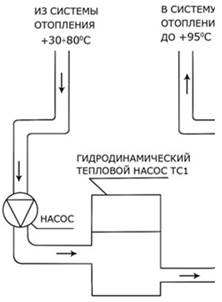
Unlike a heat pump, which can produce a heat carrier with a maximum temperature of up to +65 °C, a hydrodynamic heat pump can heat the heat carrier up to +95 °C, which means that it can be easily built into already existing system building heat supply.
In terms of capital costs for the heat supply system, a hydrodynamic heat pump is several times cheaper than a heat pump, because does not require a low-potential heat circuit. Heat pumps and thermal hydrodynamic pumps, similar in name, but different in terms of the principle of transformation electrical energy into thermal.
Like a classic heat pump, a hydrodynamic heat pump has a number of advantages:
Profitability (a hydrodynamic heat pump is 1.5-2 times more economical than electric boilers, 5-10 times more economical than diesel boilers).
· Absolute environmental friendliness (the possibility of using a hydrodynamic heat pump in places with limited MPE standards).
· Complete fire and explosion safety.
· Does not demand water treatment. During operation, as a result of the processes taking place in the heat generator of a hydrodynamic heat pump, degassing of the coolant occurs, which has a beneficial effect on the equipment and devices of the heat supply system.
· Fast installation. In the presence of electrical power supplied, the installation of an individual heat point using a hydrodynamic heat pump can be completed in 36-48 hours.
· Payback period from 6 to 18 months, due to the possibility of installation in an existing heating system.
Time to overhaul 10-12 years old. The high reliability of the hydrodynamic heat pump is inherent in its design and confirmed by many years of trouble-free operation of hydrodynamic heat pumps in Russia and abroad.
3. Autonomous heating systems
Autonomous heat supply systems are designed for heating and hot water supply of single-family and detached residential buildings. An autonomous heating and hot water supply system includes: a heat supply source (boiler) and a network of pipelines with heating devices and water fittings.
Advantages autonomous systems heating supplies are as follows:
Lack of expensive external heating networks;
Possibility of quick implementation of installation and commissioning of heating and hot water supply systems;
low initial costs;
simplification of the solution of all issues related to construction, as they are concentrated in the hands of the owner;
· reduction of fuel consumption due to local regulation of heat supply and absence of losses in heat networks.
Such heating systems, according to the principle of accepted schemes, are divided into schemes with natural circulation of the coolant and schemes with artificial circulation of the coolant. In turn, schemes with natural and artificial circulation of the coolant can be divided into one- and two-pipe. According to the principle of coolant movement, schemes can be dead-end, associated and mixed.
For systems with natural induction of the coolant, schemes with upper wiring are recommended, with one or two (depending on the load and design features houses) main risers, with expansion tank installed on the main riser.
A boiler for one-pipe systems with natural circulation can be flush with the lower heaters, but it is better if it is buried, at least to the level concrete slab, in a pit or installed in the basement.
The boiler for two-pipe heating systems with natural circulation must be buried in relation to the lower heating device. The depth of penetration is specified by calculation, but not less than 1.5-2 m. Systems with artificial (pumping) induction of the coolant have a wider range of applications. You can design circuits with top, bottom and horizontal wiring of the coolant.
Heating systems are:
water;
air;
electric, including those with a heating cable laid in the floor of heated rooms, and battery thermal ovens(designed with the permission of the power supply organization).
Water heating systems are designed vertically with heating devices installed under window openings, and with heating pipelines embedded in the floor structure. In the presence of heated surfaces, up to 30% of the heating load should be provided by heating devices installed under window openings.
Apartment air heating systems combined with ventilation should allow operation in full circulation mode (no people) only on external ventilation (intensive domestic processes) or on a mixture of external and internal ventilation in any desired ratio.
The supply air undergoes the following treatment:
· taken from outside (in the amount of sanitary standard per person 30 m3/h) mixed with recirculated air;
· it is cleared in filters;
heated in heaters;
It is supplied to the serviced premises through a network of air ducts made of metal or embedded in building structures.
Depending on the external conditions, the system must ensure the operation of the unit in 3 modes:
in the outdoor air
Full recirculation
on a mixture of external air recirculation.
4. Modern heating and hot water systems in Russia
Heaters are an element of the heating system, designed to transfer heat from the coolant to the air to the enclosing structures of the serviced premises.
A number of requirements are usually put forward for heating appliances, on the basis of which one can judge the degree of their perfection and make comparisons.
· Sanitary and hygienic. Heating appliances should, if possible, have a lower housing temperature, have smallest area horizontal surface to reduce dust deposits, allow unhindered removal of dust from the housing and enclosing surfaces of the room around them.
· Economic. Heating appliances should have the lowest reduced costs for their manufacture, installation, operation, and also have the lowest metal consumption.
· Architectural and construction. The appearance of the heater must correspond to the interior of the room, and the volume occupied by them must be the smallest, i.e. their volume per unit of heat flow should be the smallest.
· Production and installation. Maximum mechanization of work in the production and installation of heating devices should be ensured. Heating devices. Heating appliances must have sufficient mechanical strength.
· Operational. Heating devices must ensure the controllability of their heat transfer and provide heat resistance and water tightness at the maximum allowable hydrostatic pressure inside the device under operating conditions.
· Thermotechnical. Heating appliances should provide the highest density of specific heat flux per unit area (W/m).
4.1 Water heating systems
The most common heating system in Russia is water. In this case, the heat is transferred to the premises with hot water contained in the heating devices. Most the usual way - water heating with natural water circulation. The principle is simple: water moves due to differences in temperature and density. Lighter hot water rises from the heating boiler upwards. Gradually cooling down in the pipeline and heating appliances, it becomes heavier and tends down, back to the boiler. The main advantage of such a system is independence from the power supply and a fairly simple installation. Many Russian craftsmen cope with its installation on their own. In addition, a small circulation pressure makes it safe. But for the system to work, pipes of increased diameter are required. At the same time, reduced heat transfer, limited range and a large amount of time required to start, make it imperfect and suitable only for small houses.
more modern and reliable schemes heating with forced circulation. Here water is set in motion by work circulation pump. It is installed on the pipeline supplying water to the heat generator and sets the flow rate.
Quick start of the system and, as a result, quick heating of the premises is an advantage pumping system. The disadvantages include that when the power is turned off, it does not work. And this can lead to freezing and depressurization of the system. The heart of the water heating system is the source of heat supply, the heat generator. It is he who creates the energy that provides heat. Such a heart - cauldrons on different types fuel. The most popular gas boilers. Another option is a diesel fuel boiler. Electric boilers compare favorably with the absence of an open flame and combustion products. Solid fuel boilers not convenient to use due to the need for frequent heating. To do this, it is necessary to have tens of cubic meters of fuel and space for its storage. And add here the labor costs for loading and harvesting! In addition, the heat transfer mode of a solid fuel boiler is cyclical, and the air temperature in heated rooms fluctuates markedly during the day. A place to store fuel supplies is also necessary for oil-fired boilers.
Aluminum, bimetal and steel radiators
Before choosing any heating device, it is necessary to pay attention to the indicators that the device must meet: high heat transfer, low weight, modern design, small capacity, light weight. The most main characteristic heater - heat transfer, that is, the amount of heat that should be in 1 hour per 1 square meter of heating surface. The best device is considered to be the one with the highest this indicator. Heat transfer depends on many factors: the heat transfer medium, the design of the heating device, the method of installation, the color of the paint, the speed of water movement, the speed of washing the device with air. All devices of the water heating system are divided by design into panel, sectional, convectors and columnar aluminum radiators or steel.
Panel heating appliances
Manufactured from cold rolled high quality steel. They consist of one, two or three flat panels, inside of which there is a coolant, they also have ribbed surfaces that heat up from the panels. Heating of the room occurs faster than when using sectional radiators. The above panel water heating radiators are available with side or bottom connection. Side connection is used when replacing an old radiator with side connection or if the slightly unaesthetic appearance of the radiator does not interfere with the interior of the room.
Sectional water heating devices
Made from steel, cast iron or aluminium. They use the convective method of heating the room, that is, they give off heat due to the circulation of air through them. Air passes through the convector from top to bottom and heats up from a large number warm surfaces.
Convectors
Provide circulation of air in the room when warm air goes up and cold air on the contrary, it goes down and, passing through the convector, heats up again.
Steel water heating radiator can be both sectional and panel type. Steel is most often exposed to corrosion and therefore these radiators are most suitable for enclosed spaces. Two types of radiators are produced: with horizontal channels and with vertical channels.
Aluminum radiators
Aluminum radiators for water heating are lightweight and have good heat dissipation, aesthetic, but expensive. Often they don't last high pressure in system. Their advantage is that they heat up the room much faster than they do. cast iron radiators.
Bimetal radiators
Bimetallic water heating radiators consist of aluminum housing And steel pipes through which the coolant moves. Their main advantage over other radiators is durability. Their operating pressure reaches up to 40 atm, while aluminum water heating radiators operate at a pressure of 16 atm. Unfortunately, at the moment on the European market it is very rare to find data for sale. bimetal radiators water heating.
Cast iron column type radiators are the most common type of radiators. They are durable and practical to use. Cast iron radiators are produced in two-column sections. These heaters can be operated at the highest working pressure. Their disadvantage is a lot of weight and inconsistency with the design of the room. The above radiators are used in systems with poor preparation of the coolant. They are quite inexpensive in price.
4.2 Gas heating
The next most frequently used type of heating in Russia country house- gas. In this case, heaters adapted for gas combustion are installed directly in heated rooms.
gas ovens economical and have high thermal performance. Distinctive feature such furnaces - the uniformity of heating of the outer surface. As additional sources of heat, gas fireplaces are used, which also give special comfort to the interior.
Dignity gas heating lies primarily in the relatively low cost of natural gas. Its use allows you to automate the process of fuel combustion, significantly increases the efficiency of heating equipment, and reduces operating costs. But it is explosive and unacceptable for self-manufacturing and installation.
4.3 Air heating
Air heating systems are distinguished depending on the method of creating air circulation: gravitational and fan. Gravity air system heating is based on the difference in air density at different temperatures. During the warm-up process, natural air circulation in the system occurs. The fan system uses electric fan, which increases the air pressure and distributes it through the air ducts and rooms (forced mechanical circulation).
The air is heated in heaters heated from the inside by water, steam, electricity or hot gases. The heater is placed either in a separate fan chamber (central heating system) or directly in the room that is heated (local system).
The absence of a freezing coolant makes this type of heating successful for houses with intermittent use. Air heating will quickly warm up the house, and automatic regulators will maintain the temperature you set. The disadvantages of such heating can only be attributed to the danger of the spread of harmful substances by moving air.
4.4 Electric heating
Systems of direct stationary electric heating are very reliable, environmentally friendly and safe. Up to 70% of low-rise buildings in Scandinavia and Finland are heated by electricity. Equipment for electric heating can be divided into 4 groups: - wall-mounted electric convectors; - ceiling heaters; - cable and film systems for floor and ceiling heating; - control thermostats and programmable devices.
This variety makes it easy to choose suitable option for each specific room. Equipment and operating costs for electrical systems are very low. Systems can automatically turn on and off to maintain the temperature at a given level. Let's say lower it to a minimum for the duration of your absence. This feature significantly saves energy costs. Rising prices for different kinds fuels make electric heating very attractive for owners of private houses. The disadvantage of electric heating systems is that you will have to install additional equipment to provide the house with hot water. In addition, we still have long blackouts, and the owners of such a system should consider an additional source of heating - just in case.
4.5 Piping
Pipelines for supplying coolant to heating appliances can be made of steel water and gas pipes, copper pipes and from polymeric materials ( metal-plastic pipes, polypropylene pipes and cross-linked polypropylene pipes). Lines made of steel pipes are not suitable for concealed connections to radiators. All other pipes can be "hidden" under finishing materials subject to certain system installation technologies. It should also be noted that it is not allowed to install a heating system from copper pipes if aluminum sectional radiators are selected as heating devices.
4.6 Boiler equipment
As a rule, heating of urban dwellings is provided from centralized boiler houses and city heating networks, while heating country houses is mainly carried out from own (autonomous) heat sources and only occasionally from a boiler house operating for a group of buildings.
The market for boiler equipment in Russia is quite saturated. Almost all leading Western companies producing boiler equipment have their own representative offices here. Although Russian boilers are widely represented on the market, they still cannot compete with imported samples in terms of consumer qualities. At the same time, almost all Western manufacturers develop and supply Russian market boilers adapted to our conditions:
multi-fuel boilers;
· gas boilers operating without electricity.
Multi-fuel boilers
Almost all companies produce boilers operating on liquid fuel and gas, and some companies add the option solid fuel. It should be noted that multi-fuel boilers, due to the design of the burner, are quite noisy.
gas boilers working without electricity
Now the majority of boilers are designed to work in heating systems with forced circulation of the coolant, and, in a typical case of a power outage in Russia, the boiler simply stops and does not work until there is electricity.
Boiler control systems
The control system for boiler equipment, depending on the purpose of the boiler room (only heating of one building, heating and hot water supply, the presence of underfloor heating circuits, heating and hot water supply of several buildings), can vary from the simplest, made on thermostatic controllers, to complex with microprocessor control.
5. Prospects for the development of heat supply in Russia
The main factors determining the prospects for the development of heat supply in Russia include:
1. A course towards restructuring the unified energy system with the formation of a 3-level system of enterprises: heat producers, heat networks and energy sellers. The restructuring will be accompanied by a redistribution of ownership in the energy complex in favor of private entrepreneurship. It is expected to attract large investments, including from abroad. In this case, the restructuring will affect the "large" energy sector.
2. Housing and communal reform associated with the reduction and removal of subsidies to the population in payment utilities, including thermal energy.
3. Stable economic growth in the construction industry.
4. Integration into the country's economy of advanced heat and power technologies of Western countries.
5. Revision of the regulatory framework for thermal power engineering, taking into account the interests of large investors.
6. Approximation of domestic prices for fuel and energy resources to world prices. Formation of a “deficit” of fuel resources of export potential in the domestic market, primarily natural gas and oil. Increasing the share of coal and peat in the country's fuel balance.
7. Formation of a balance of municipal and market mechanisms for the organization and management of regional heat supply.
8. Formation of modern accounting and billing systems in the market for the production, supply and consumption of thermal energy.
Conclusion
Russia belongs to the countries with high level centralization of heat supply. Energy, environmental and technical advantage centralized heat supply over autonomous in the conditions of a monopoly of state ownership was considered a priori. Autonomous and individual heat supply of individual houses was taken out of the scope of energy and developed according to the residual principle.
In the district heating system, CHPPs are widely used - enterprises for the combined generation of electricity and heat. Technologically, CHPPs are focused on the priority of power supply, the heat produced by the process is in demand to a greater extent in the cold season, and discharged into the environment - in the warm season. It is far from always possible to harmonize the modes of production of heat and electric energy with the modes of their consumption. Nevertheless, the high level of large-scale power engineering predetermined “technological independence” and even a certain export potential of the country, which cannot be said about small-scale thermal power engineering. Low prices for fuel resources, economically unjustified price of thermal energy did not contribute to the development of "small" boiler building technologies.
Heat supply is an important industry in our life. It brings warmth to our home, provides coziness and comfort, as well as hot water supply, which is necessary every day in the modern world.
Modern heat supply systems significantly save resources, are more convenient to use, meet sanitary and hygienic requirements, are smaller in size and look more aesthetically pleasing.
Bibliography
1. http://www.rosteplo.ru
2. http://dom.ustanovi.ru
3. http://www.boatanchors.ru
4. http://whttp://www.ecoteplo.ru
(Document)
n1.doc
I Course of lectures for the first half of the yearSources and systems of heat supply of enterprises
Heating systems manufacturing enterprises
Types of thermal loads
Classification of heat supply systems
By type of coolant (steam systems and water systems);
According to the method of heat supply to the consumer; (for heating: dependent and independent ; for hot heat supply:closed and open )
By the number of parallel heating pipelines;
According to the number of connection steps.
4. Schemes of thermal networks (dead end, radial, ring)
5. Steam heating systems (SST).
6. Equipment for heating networks
Heat supply systems of enterprises (STSPP)
is a complex of devices for the production, transportation and provision of consumers necessary quantity heat of the required parameters.
The heat supply system (Fig. 1) includes:
1. Source (CHP, boiler house);
2. Main networks (thermal);
3. Distribution networks(thermal);
4. Heat consumers (industrial consumers,
Residential and public utility facilities);
5. Subscriber input (thermal unit, local heating point MTP, elevator unit);
6. Central heating point of the central heating substation.
Fig.1. Heating system.
Types of thermal loads:
Heat load consumption:
ventilation (heat in the heater (heat exchanger);
hot water supply;
technological needs p.p.
Thermal loads are distinguished:
seasonal (heating, ventilation);
year-round (hot water supply, technological needs).
according to the scheme of heat supply to the consumer;
by type of coolant;
according to the method of heat supply to the consumer;
by the number of parallel heating pipelines;
according to the number of connection steps.
Decentralized - a source of heat at the place of consumption. In this case, there are no heating networks; are used in areas with a low concentration of heat load, when small buildings are located on loosely built-up areas, as well as in feasibility studies.
Centralized - the source of heat supply (CHP or boiler house) is located at a considerable distance from heat consumers. Therefore, each STS consists of three links (heat source - heat networks - local heat supply systems). Local STS - thermal substations and heat receivers.
Centralized heating systems have advantages over decentralized ones, and currently C T determine the leading role in the development of heat supply to large cities and industrial enterprises. In Petrozavodsk, a thermal power plant was put into operation in 1977.
2. By type of coolant:
Steam systems (coolant - water vapor);
Water systems (coolant - hot water).
Hot water is used to satisfy heating, ventilation and hot water loads. Water vapor is used in enterprises for technological needs (superheated water is rarely used). At the required coolant temperature at the consumer up to 150˚C, hot water is used, and at higher parameters, steam is used. There are special requirements for coolants:
A. sanitary and hygienic (in the premises of housing and communal services, the temperature of heated appliances is not allowed above 90 ° C, in industrial workshops it can be even higher);
B. technical and economic (the cost of material, installation and operation should be optimal);
B. operational (the coolant must have qualities that would allow centralized regulation of the heat transfer of consumption systems).
Comparative characteristics of water and steam as a heat carrier:
Advantages of water: wide temperature range (from 25˚ to 150˚С); the possibility of transportation over long distances without reducing its thermal potential (15-20 km); the possibility of centralized control of the temperature of the coolant at the source; ease of connection of local systems to heating networks.
Disadvantages of water: a significant consumption of electricity is required for the operation of pumps for pumping heat; the coolant temperature may be less than the set one.
Advantages of steam: they are used both for thermal consumers and for power and technological needs; fast heating and cooling of the system, which is valuable for rooms where heating is periodically required; in steam systems, hydrostatic pressure can be ignored due to the low bulk density (1650 times less than the volume of water). Steam systems can be used in mountainous areas and in high-rise buildings; no electricity consumption for steam transportation (without pumps); ease of initial adjustment due to self-regulation of steam.
Disadvantages of steam: when transporting over long distances, there are large losses in temperature and pressure, so the radius of steam systems is only 6-15 km, and that of water systems is from 30 to 60 km. The service life of steam systems is much lower than that of water systems due to pipe corrosion.
3. According to the method of heat supply to the consumer :
For heating - HV connection diagrams: dependent and independent;
For hot heat supply - TS connection schemes: closed and open.
Dependent connection scheme - when water from the heating network directly enters the heating devices of the local heating system(MOS).
Independent connection scheme - when there are two separate circuits (primary - water circulating in the heating network, and secondary - the house's own circuit, water circulating in the MOS), while the water from the heating network through the heat exchanger gives off heat to the water of its own circuit. Water from the TS reaches only the thermal substation of the MOS (a thermal substation is a TsTP or MTP), where water is heated in heaters (heat exchangers TA), which circulates in the MOS. In this case, there are two coolants: heating (water from the TS) and heated (water in the MOS). The pressure of the primary circuit is not transferred to the pressure of the secondary circuit, which operates due to its own circulation pump.
Open water intake - directly from the heating network. Closed water intake - through the heat exchanger, water from the vehicle heats the drinking water.
The equipment of a thermal substation with a dependent circuit is simpler and cheaper than with an independent one, however, it must be borne in mind that in dependent circuits, pressure is transferred from the heating network to the MOS, which can withstand pressures up to 6-10 atm. depending on the type of heaters. Example: cast iron radiators withstand 6 atm.
Schemes for connecting heating systems to heat networks: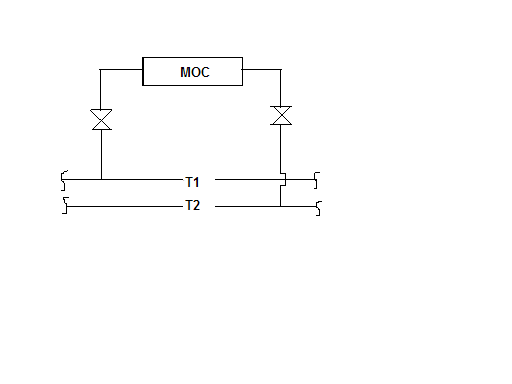
T 1 – supply heat pipe TS,
-1 -1 T 2 - return pipeline of the vehicle,
1 - armature of the disconnecting device.
Rice. 2. Dependent scheme without mixing
The temperature in the supply pipeline of the vehicle does not exceed the limit established by sanitary standards for devices of local systems. This is possible in the case of a small heat source, when the boiler room produces a heat carrier with parameters of 95˚-70˚С or in the heating system of industrial buildings t ? 100˚ C, but it is acceptable.
Dependent scheme with elevator mixing (Fig. 3).
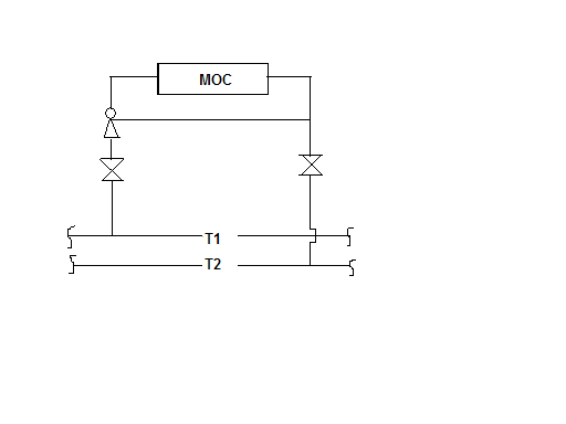
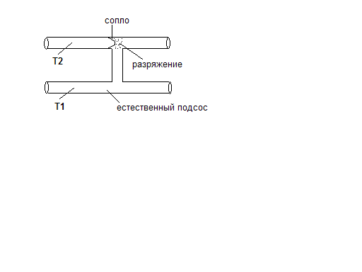
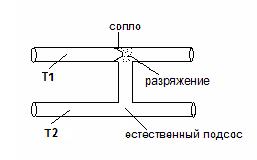
? 130˚С ? 90-95˚С
70˚C?
Rice. Fig. 3. Dependent scheme with elevator mixing. 4. Elevator
Supply water T 1 s t = 130˚ C enters the elevator (Fig. 4), water from the reverse local network is sucked through the pipe to the elevator T 2 t =70˚ C . Thanks to the nozzle, which is built into the elevator, and according to the principle of injection, mixing takes place t = 130˚ C and t =70˚ C , mixed water t = 90˚С enters the heating devices. The elevators are calculated and the nozzle diameter is selected. In our country, most of the entrances to buildings are equipped with elevators where superheated water is transported through heating networks. It must be taken into account that the operation of the elevator requires a head on the water of 15 m of the water column.
Dependent circuit with pump mixing (Fig. 5).
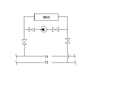 In case of insufficient pressure, put
Centrifugal pump at the jumper between
90˚C? 70˚С ? supply and return pipelines and it
How the elevator mixes with the feed water
Return chilled water. But the pump
Expensive equipment.
130˚C? There is a scheme with both an elevator and a pump.
Rice. 5. Dependent circuit with pump mixing
Independent circuit (with a heat exchanger) (Fig. 6).
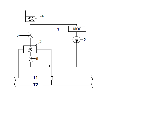 An independent circuit divides the MOS into two circuits, preventing pressure fluctuations. Both circuits are hydraulically isolated and independent of each other. In this scheme, it is easy to take into account the need for heat, regulate the heat supply, i.e. eliminate the problem of overheating, and, consequently, save.
 1. Local heating system;
2. Circulation pump;
3. Heat exchanger;
4. Expanded tank;
5. Shutdown fittings.
Rice. 6. Independent circuit (with heat exchanger)
Schemes for connecting hot water supply to heating networks.
In closed heating systems the coolant is completely returned to
Closed circuits distinguish between single-stage and multi-stage. The choice of scheme depends on the ratio of heat consumption for heating and hot water. The choice of the connection scheme is made on the basis of the calculation.
In open systems DHW use not only the heat supplied
Schemes for connecting hot water supply systems of buildings to heat networks.
Single-stage schemes (Fig. 7, 8):
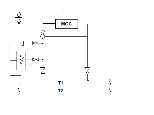
One heat exchanger and DHW heating takes place before the WTP).
Rice. 7. Single stage upstream
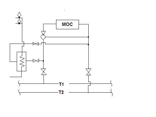
?
Rice. 8. Single stage parallel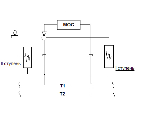
T = 55-60˚С
Т = 30˚С Т = 5˚С
Rice. 9. Sequential two-stage
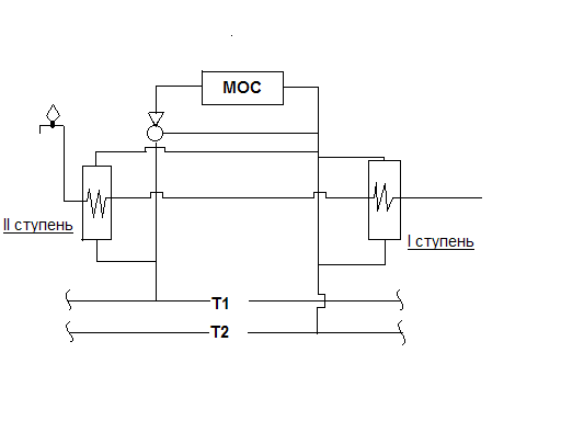
Rice. 10. Mixed two-stage
Two-stage schemes are effective in application in that there is a deep decrease in the return water temperature, and there is also an independent heat consumption for heating and hot water supply, i.e. flow fluctuations in the DHW system do not affect the operation of the MOS, which can occur in open circuits.
4. According to the number of parallel heating pipelines.
Depending on the number of pipes transferring the coolantin one direction distinguish between one-, two- and multi-pipe systems of the vehicle. According to the minimum number of pipes can be:
An open one-pipe system is used for centralized heating for technological and domestic needs, when all network water is taken apart by consumers when heat is supplied to heating, ventilation and hot water supply, i.e. When Q from + Q vent. = Q hot water . Such situations are typical for the southern regions and technological consumers (rare).
The two-pipe system is the most common, it consists of supply (T1) and return (T2) pipelines.
Three-pipe - consists of connecting a two-pipe water supply system for heating and ventilation and a third pipe for hot water purposes, which is not very convenient.
Four-pipe - when a circulation pipeline is added to the hot water supply.
Symbols of pipelines in accordance with GOST:
supply pipeline (T 1 ),
return pipeline (T 2 ),
DHW pipeline (T 3 ),
DHW circulation pipe (T 4 ),
pipeline for technological needs (Тт).
There are single-stage and multi-stage schemes of heat supply systems.
Single-stage scheme (Fig. 11) - when heat consumers are connected to heat networks using MTP.
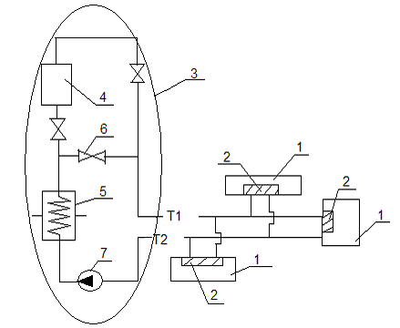
Rice. 11. One-stage scheme
1- heat consumers,
2-local thermal units (MTP),
3- element of an industrial boiler house with steam and hot water boilers,
4- hot water boiler (peak),
5- network steam-water heater,
6- jumper with shut-off fittings for creating various operating modes (to turn off the boiler),
7- network pump,
8- TsTP.
Two-stage scheme (Fig. 12).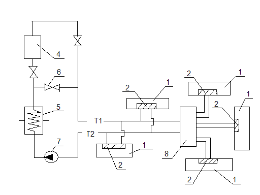
Rice. 12. Two-stage scheme
Multi-stage scheme - when central heating and group heating are placed between the heat source and consumers heat points(GTP). These points are designed for the preparation of heat carriers of the required parameters, for regulating the heat consumption and distribution to local consumer systems, as well as for accounting and controlling the consumption of heat and water.
Heating network schemes
Heating network schemes depend on:
Placement of heat sources in relation to the area of consumption;
From the nature of the thermal load;
From the type of coolant (steam, water).
Thermal networks are divided into categories:
Backbone networks;
Distribution networks;
Intra-quarter networks;
Branches to consumers (buildings).
Dead end (Fig. 13) - the simplest, is widespread in villages and small towns:
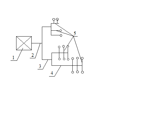 1-source,
2-backbone networks,
3-distribution networks,
4-quarter networks,
5 branches,
6- consumers,
7 jumper.
Rice. 13 Dead end scheme
Radial (Fig. 14) - arranged when it is not possible to provide for a ring, but a break in heat supply is unacceptable:
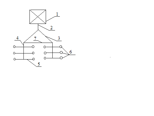
Rice. 14 Radial scheme
Ring - the most expensive, is being built in large cities, provides uninterrupted heat supply, for which a second source of thermal energy should be provided:
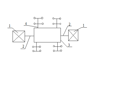
Rice. 15 Ring diagram
Steam heating systems (SST).
Steam heating systems are mainly used in large industrial enterprises and can be used at facilities surrounding industrial consumers, as well as in cities with unfavorable terrain.
Types of steam systems:
1-one-pipe (Fig. 16) (no condensate return to the system):
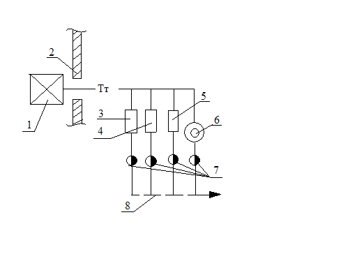 1-source (steam boiler),
2-wall of an industrial consumer - the boundary of the consumer's subscriber input,
3-heater,
5-steam-water heat exchanger for MOS,
6-technological unit,
Rice. 16 Single pipe steam system7-condensate traps,
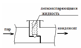 8- discharge of condensate into the drain.
Rice. 17 Automatic steam trap.
It is advisable to use a single-pipe scheme when, according to the conditions technological process the condensate has significant impurities and the quality of these impurities is ineffective for cleaning. This scheme is used for heating fuel oil, steaming reinforced concrete products.
2-two-pipe (Fig. 18):
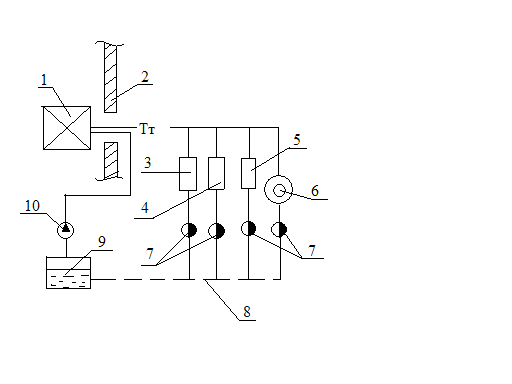 1-source (steam boiler),
2-wall industrial
Consumer - border
Subscriber input of the consumer,
3-heater,
4-steam heat exchanger for
5-steam heat exchanger for
6-technological unit,
7-condensate traps,
Rice. 18 Two-pipe steam system8-condensate line,
9-condensate tank,
10-condensate pump.
Two-pipe systems with condensate return are used if the condensate does not contain aggressive salts and other contaminants (i.e. it is conditionally clean). The circuits are usually laid in such a way that condensate enters the condensate tank by gravity.
3-multi-pipe (Fig. 19):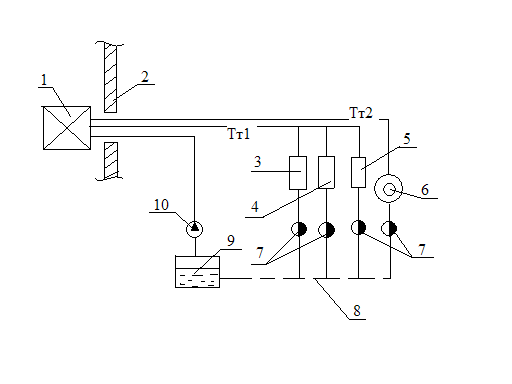
Rice. 19 Three-pipe steam system
A three-pipe (multi-pipe) scheme is used when the consumer needs steam of various parameters. The boiler room produces steam with the maximum pressure and temperature required by one of the consumers. If there are consumers who require steam with lower parameters, then the steam is passed through a pressure reducing unit (RU), in which steam reduces only the pressure, or through a pressure reducing cooling unit (ROC), if both pressure and temperature are to be reduced.
Heating network equipment
There are the following ways of laying heating networks:
Overground (ground) laying - takes place on the territory of industrial enterprises, at the intersection of roads and obstacles, in permafrost areas;
Underground laying happens:
In semi-through channels,
In passage channels (collectors),
Channelless.
Collectors and semi-through channels take place in large cities, on the territory of industrial enterprises, where it makes sense to lay various engineering networks (communications) together. This method of laying is convenient in network maintenance, but expensive. Pipes of heating networks laid in impassable channels and without channels are not serviced. Thus, the choice of laying networks depends on the conditions of the territory, type of soil, development and feasibility study.
The depth of laying heating networks depends on the place of laying. The maximum depth in the impassable part is 0.5 m to the top of the channel, in the carriageway - 0.7 m.  ί
min =0.002 (ί min = h / L ).
ί
min =0.002 (ί min = h / L ).
Heating network equipment, which requires constant monitoring and maintenance, is installed in heating chambers (Fig. 20). These are: gate valves, butterfly valves, control valves, devices for venting air and draining water (emptying the network). As a rule, fixed supports are constructed together with the chamber. It is necessary to build (in water-saturated soils) drainage networks (pipes with holes on top and sides are laid on sand preparation and covered with crushed stone).
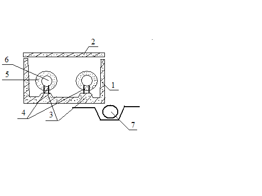
Rice. 20 Heating chamber
In heat networks, electric-welded or seamless pipes are used, and options and cast iron pipes from high-strength spheroidal graphite cast iron.
For yard networks at operating pressure Р slave up to 1.6 MPa and temperature T up to 115˚С, non-metallic (plastic) pipes can be used.
Support structures.
There are: - movable (free) supports,
Fixed (dead) supports.
Movable supports are designed to absorb the weight of the pipe and ensure free movement of pipes (with thermal elongations). The number of movable supports is determined according to the tables depending on the diameter and weight of the pipe. According to the principle of free movement, movable supports are divided into: sliding supports (sliders), roller, ball, movable.
Movable supports are used in all laying methods, except channelless.
Fixed supports are used to perceive thermal deformation by fixing the pipeline, as well as to delimit the areas of thermal elongation compensation. There are fixed supports:
Shield (for underground laying),
On a beam, on a foundation, on racks (when laying above ground or in tunnels).
Thermal elongation compensation.
Compensators are designed to absorb thermal elongation of the heat pipe and unload pipes from thermal stresses and deformations. In thermal networks, the following types of compensators are used: 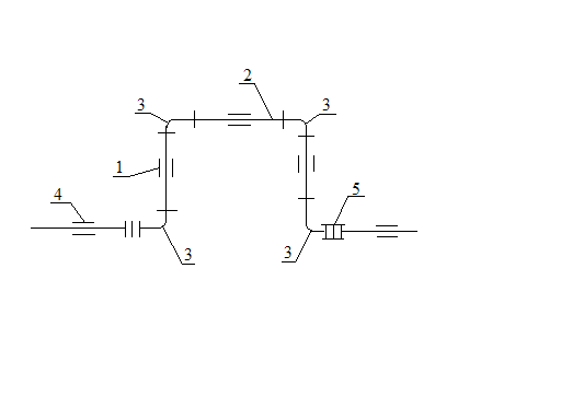
departure of the compensator,
compensator back,
welded bends,
movable supports
tie bolts,
 installed onRice. 21 Flexible (U-shaped) supportclamps.
∆l = ? ∙ L (? max - ? min), where ? is the coefficient of linear expansion,
L - length between fixed supports (compensation section).
U-shaped expansion joints are stretched by half of the thermal elongation. Stretching is done at the first welded joints from the compensator.
U-shaped compensators, as well as the angles of rotation, do not require maintenance.
track turning angles (self-compensation),
bellows, lens (one or many corrugations),
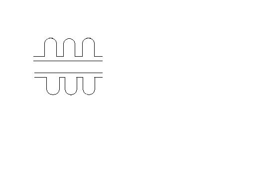 Compensating capacity of the bellows expansion joint
 It is 50-150 mm.
Bellows three-wave compensator.
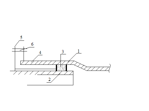
1-building,
2-glass,
3-gland packing,
4-primer box,
5-pressure flange,
6 pinch bolt.
Rice. 22 Gland compensator
The gland compensator can be one-sided and two-sided.
Line rotation angles and U-shaped compensators work as radial ones, and bellows, lens and stuffing boxes - as axial ones.
Channelless laying.
For thermal networks of channelless laying, pipelines with polyurethane foam insulation (PPU-insulation) are used. Russia is the country with the highest level of district heating, the length of heating networks in our country is about 260 thousand kilometers, and in Karelia - about 999 thousand meters. Of these, 50% of heating networks require major repairs. Thermal networks lose 30% of their heat output, which is approximately 80 Mtce/year. To solve these problems, channelless laying with polyurethane foam insulation is proposed. Benefits of this gasket:
Increased durability from 10 to 30 years,
Reducing heat loss from 30% to 3%,
Reducing operating costs by 9 times,
Reducing the cost of repairing heating mains by 3 times,
Reduced construction time
The presence of a system of operational-remote control (ODC) for moistening the insulating layer.
Accumulated defects statistics:
38% - damage by third parties to the UEC system,
32% damage to steel shells,
14% - damage to butt joints,
8% - ODK assembly errors,
2% - poor quality welding,
6% - internal corrosion of the metal.
For channelless laying, a polyethylene sheath is used.
(Document)
n1.doc
Ministry of General Education of the Russian Federation
South Ural State University
Department of Industrial Heat Power Engineering
LECTURE NOTES
BY DISCIPLINE
"SOURCES AND SYSTEMS OF HEAT SUPPLY OF INDUSTRIAL ENTERPRISES"
INTRODUCTION
There are two types of heat supply - centralized and decentralized. With decentralized heat supply, the source and consumer of heat are close to each other. Heating network absent. Decentralized heat supply is divided into local (heat supply from a local boiler house) and individual (stove, heat supply from boilers in apartments).
Depending on the degree of centralization, district heating systems (DH) can be divided into four groups:
group heat supply (TS) of a group of buildings;
regional- TS of the urban area;
urban– TC of the city;
intercity– Vehicles of several cities.
Preparation of HP is carried out at heat-preparation plants of CHP and boiler houses. HP transport is carried out through heating networks. The use of HP is carried out at heat-using installations of consumers.
The complex of installations designed for the preparation, transport and use of the coolant is called the district heating system.
There are two main categories of heat consumption.
To create comfortable working and living conditions (household load).
2. For the production of products of a given quality (technological load).
According to the temperature level, heat is divided into:
Low potential, with temperature up to 150 0 С;
Medium potential, with temperature from 150 0 С to 400 0 С;
High-potential, with a temperature above 400 0 С.
Municipal load refers to low-potential processes.
The maximum temperature in heat networks does not exceed 150 0 С (in the direct pipeline), the minimum temperature is 70 0 С (in the return pipeline).
To cover the technological load, as a rule, water vapor with a pressure of up to 1.4 MPa is used.
As heat sources, heat treatment plants of thermal power plants and boiler houses are used. The combined heat and power generation is carried out at the CHPP based on the heating cycle. Separate generation of heat and electricity is carried out in boiler houses and condensing power plants. With combined generation, the total fuel consumption is lower than with separate generation.
1. CALCULATION OF HEAT CONSUMPTION
Heat load can be divided into seasonal and year-round. The change in seasonal load depends mainly on climatic conditions - outdoor temperature, humidity, wind speed, solar radiation, etc. The main role is played by the change in the temperature of the outside air. The seasonal load has a relatively constant daily schedule and a variable annual one. Seasonal loads include heating, ventilation (winter loads), and air conditioning (summer loads). The year-round load includes the load of hot water supply (DHW) and the technological load. The schedule of technological load depends on the nature of production. The load schedule for hot water supply depends on the improvement of buildings, the composition of the population, the schedule of the working day, and the mode of operation of utilities. Technological and load of hot water supply weakly depend on the time of year.
1.1. seasonal load.
The purpose of heating is to maintain the temperature of the internal air in the room at a given level. The air temperature in the room depends on the purpose of the room, and in industrial buildings on the nature of the work performed. The values of the air temperature in the premises are taken according to. In particular,
For residential buildings - from 18 to 20 0 C;
For industrial buildings - from 16 to 20 0 С;
For public buildings - from 14 to 25 0 C.
Calculation of heat supply for heating.
To maintain the temperature of the air in the room constant, it is necessary to ensure the equality of heat losses and heat gains. Heat losses are due to heat transfer through the fences, where the temperature difference is more than 5 0 C - Q t, as well as infiltration, Q inf - heat costs for heating the air coming from the outside through the leakage of the fences.
 - coefficient of infiltration.
In industrial premises, heat is also consumed for heating materials and Vehicle coming from outside - Q mt.
The influx of heat into the premises is carried out through heating installations - Q o and from internal heat release - Q watts.
In general, the heat balance can be written as
For residential and public buildings:
Q mt \u003d Q inf \u003d Q w \u003d 0, then Q o \u003d Q t.
For industrial premises:
Q o \u003d Q t (1 +  ) + Q mt - Q w
 in industrial premises can be 25 ... 35% of Q o
Here: b– constant infiltration, b=(35…40) 10 -2 ;

g- acceleration of gravity;
L- the height of the opening into which air enters;
T n- outdoor air temperature, K;
T V- air temperature in the room, K;
W- wind speed, m/s.
Heat loss by heat transfer is calculated by the equation
 , or
, or
 , (1.1)
n- Correction for temperature difference. Taken into account for the floor of the 1st floor and the upper ceiling (n  1);
1);
 - coefficient that takes into account additives for orientation relative to the cardinal points, the number of storeys of the building, wind speed, placement of premises in the building. Provided in SNiP.
Where  - an amendment that takes into account the orientation to the cardinal points.
Formula (1.1) is used in the design of heating systems for a particular building, that is, according to the results of calculations, the number of heating devices installed in the premises is determined.
When designing heat sources, the heat demand for heating can be determined by aggregated indicators.
1.1.1.1. Determination of heat consumption for heating by volume of the building.
![]()
Where:
q O- the heating characteristic of the building, depending on the volume and purpose of the building. It is given in SNiP, as well as in. ; V- the volume of the building according to the external measurement.
The maximum heat loss and, accordingly, the maximum heat supply for heating is determined by the calculated temperature for heating - t But . This is the average temperature of the coldest five-day period of eight winters over the past 50 years.
When calculating according to aggregated indicators in the absence of a list of buildings indicating their purpose, t in is taken equal to 18 0 C, if t but  -31 0 С and equal to 20 0 С, if
t but -31 0 С.
For residential and public buildings, the estimated amount of heat for heating is determined by the formula
 .
.
At 
 .
.
For economical use of fuel, the correct choice of the beginning and end of the heating period is of great importance. According to SNiP, the beginning and end of the heating period is taken at the value of the average daily temperature equal to +8 0 C. For industrial premises with internal heat emissions, the heating period begins at the outdoor air temperature at which  .
.
For industrial buildings:
At t n t but
When t n > t but
![]()
D  The duration of the heating period is determined by the number of days with a stable average daily temperature less than and equal to +8 0 С.
![]()
2
1 - for residential and public buildings;
2 - for industrial buildings.
Fig.1.1. Schedule of heat supply for heating.
Determination of heat consumption for heating by building area

 ,
,where q F - heat supply per 1 m 2 of building area, W / m 2; F- built-up area, m 2.
F \u003d f beats z, where z is the number of inhabitants;
f sp \u003d 12.5 m 2 / person - for buildings built before 1980; f sp \u003d 18 m 2 / person - for buildings built after 1980;
k 1 =0.25 - coefficient taking into account heat supply for heating public buildings. When t n > t but
1.1.2. Calculation of heat supply for ventilation
Under the ventilation load is understood the need for heat to heat the air supplied from the outside to the premises. In residential buildings without special supply system ventilation heat consumption Q in \u003d 0.
For public and industrial buildings:
Q V = C' V V (t V -t n ) m ,
Where WITH'- volumetric heat capacity of air, 1260 J / (m 3 K);
V V- the volume of the ventilated room according to internal measurement;
m- air exchange rate in the room.
When calculating according to aggregated indicators, heat supply is determined with a known
volume of the building.
Q V = q V V(t V -t n ).
For public buildings located in a residential area

Where k 2 = 0.4 - for old buildings, k 2 = 0.6 - for new buildings.
A - with a slight release of harmful substances. The maximum heat output for these buildings is determined by the design temperature for ventilation - t nv- the average temperature of the coldest period, which is 15% of the duration of the heating season.

At  the supply of heat for ventilation does not increase, while the frequency of air exchange decreases. The minimum value of the exchange rate reaches at
  .
.
 .
.
At 
 .
.
B - buildings with a significant emission of hazards:

B - with a special technical justification (a lot of hazards)  determined by the average temperature of the coldest day.

8 t nv t but t n, 0 C
Fig.1.2. Heat release schedule for ventilation
Year-round load includes process load and DHW load. The technological load is set by technologists and depends on the type of production.
The DHW load has a significantly uneven character both during the day and on the days of the week. The highest consumption of hot water is observed in the morning and evening hours, from the days of the week - on Saturday.
The average weekly heat consumption for hot water supply of individual residential, public and industrial buildings is determined by the formula
 , Where
Fig.1.3. Graphs of heat consumption for hot water supply.
a –
hot water consumption rate t\u003d 60 0 C per unit of measurement; m– number of units of measurement; With– heat capacity of water, 4190 J/(kgK); t G ,
t X– temperature of hot and cold water; n c- estimated duration of water supply to hot water supply, sec./day. or hour/day In winter they take t X
=5 0 C, in summer - t X=15 0 C. Value A given for
t G= 60 0 C. For other values t X
 .
.
Hot water temperature for open systems must be maintained at the points of water intake - not lower than 60 0 C and not higher than 70 0 C; for closed systems - not lower than 55 0 C and not higher than 75 0 C. For residential buildings, hospitals, kindergartens, sanatoriums, rest homes, etc. n c =86400 sec/day, or 24 hours/day In the absence of data on the number and type of residential and public buildings in new areas, the average weekly heat consumption for hot water supply can be determined by the formula
A= 80 ... 120 l / day per person for residential buildings, V=18…22 l/day per person for public buildings. In summer
 .
.
The average heat consumption for hot water supply for the day of the highest water consumption is equal to  , Where
  - coefficient of weekly unevenness, equal to 1.2 for residential and public buildings. For industrial buildings =1. Estimated (maximum-hourly) heat consumption for hot water supply is equal to
  . Here
  - coefficient of daily unevenness. For cities =1.7…2.2, for industrial buildings =1.

Fig.1.4. Heat supply schedule for hot water supply
According to the method of supplying heat to hot water supply, open and closed heat supply systems are distinguished.
In open systems, hot water is supplied from the heating network.
Subscriber input scheme:
OK - check valve; E - water jet ejector or elevator; RT - temperature controller; B - air vent; OP - heating device; C - mixer.
Fig.1.5. open circuit connection of a subscriber unit
In closed systems, network water is used to heat secondary water entering the DHW system, i.e. water-to-water heaters 1 or 2 are installed at the subscriber input of closed systems. Their connection can be single-stage or two-stage, made in parallel, two-stage serial or two-stage mixed circuits.
Fig.1.6. Two-stage sequential scheme for connecting the DHW system
1.2. Calculation of the annual heat supply. Heat load schedule.
To build a graph, you need data on standing temperatures. Given in reference books:
40...-35 0 С - n 1 hours;
35...-30 0 С - n 2 hours;
30...-25 0 С - n 3 hours;
......................……………
0...+5 0 С - n i-1 hours;
5...+10 0 С - n i hours.
Fig.1.7. Graph of the duration of the total heat load
The abscissa shows the number of hours during which the temperature is equal to or less than the given one. On the y-axis, hourly heat consumption is plotted. Let's plot two rectangles on the chart, the area of which is equal to the area of the chart. Then for the rectangle 0BCD0 the height CD is equal to the average heat consumption for the heating period. For rectangle 0KLN0, segment 0N represents the duration of use of the design heat load per season.
If the heat load is provided from various sources, then it is convenient to use the integral graph. The graph of the duration of the total heat load is divided into equal intervals along the y-axis. a is the relative thermal load. a c =  - the ratio of the heat load of the i-th source to the calculated load of the area.
 - the ratio of the amount of heat source for the season to the total heat consumption for the season. Then the area 0abc0 is equal to the heat consumption from the source, the power of which is equal to 20% of the calculated one, i.e.
  .
.
Integral graphs constructed for any one geographical point can be used with sufficient accuracy for the entire climatic zone. 
Fig.1.8. Integral heat load curve
F 0
abc 0
/
F=0.4 – point A. At  we get
  - t.V, etc.
For example, there are two heat sources. One has a power equal to 60% of the maximum consumption,  . The other is able to cover the remaining 40%. In this case, the first source can provide 92% of the maximum heat demand, the second - 8%.
1.3. Water heating systems
Water heating systems are divided into open and closed. In open systems, water is taken from the heating network for the needs of hot water supply. In closed systems, hot water is heated by network water in heat exchangers. Connection schemes for DHW installations are shown in Fig. 1.5, 1.6. According to the number of pipelines, TS systems are divided into one-, two-, three- and multi-pipe systems. open system The vehicle must have at least one pipe. IN closed system at least two pipelines are required. Most cities use two-pipe systems. They are used when all consumers need heat at approximately the same potential. Where a higher potential load is also required, a three-pipe system is used. In this case, two lines are supply, and one is return. Depending on the nature of the subscriber installations, one or another scheme for connecting them to the heating network is selected.
Heating installations can be connected according to dependent and independent schemes. With dependent connection, the water circulating in the heating system is heated in the heat exchanger with water from the heating network. In a dependent scheme, water is supplied to the heating devices from the heating network. At the same time, there is a rigid hydraulic connection between the heating system and the heating network. Maximum pressure in heating installation limited by the strength of the heaters. Reliability dependent systems small.
2. HEAT LOAD CONTROL
The heat load varies during the heating season. Therefore, to maintain the required thermal regime heat load needs to be regulated.
There are central, group, local and individual regulation. Central regulation is carried out at CHP and boiler houses. Group - at group thermal substations. Local - at local thermal substations. Individual - directly from subscribers.
If the heat load of all consumers is approximately the same, then you can limit yourself to central regulation. In most cases, the thermal load is non-uniform. In this case, central regulation is carried out according to the characteristic heat load for most consumers. First of all, this is the heating load and the combined load of heating and hot water. In the second case, the water flow in the TS increases slightly compared to the heating load regulation or does not change.
The main amount of heat in subscriber systems is spent on heating. Therefore, the heat load primarily depends on the mode of heat transfer. Heat transfer is described by the heat transfer equation
 (2.1)
(2.1)
Where n- the duration of the system; F is the area of the heat exchange surface; k- heat transfer coefficient; D have limitations. The temperature of the network water cannot be lower than 60 0 C, necessary to ensure the temperature DHW water and cannot be higher than the saturation temperature for a given pressure. The water flow rate is determined by the available pressure drop across the GTP and MTP. If one of the heat carriers is steam, then its temperature can be changed by changing the pressure (by throttling).
In water systems, it is really possible to change the heat load in three ways:
change in the temperature of network water - quality regulation;
change in network water consumption - quantitative regulation;
change in water flow and temperature - qualitative-quantitative regulation.
The choice of control method depends on the hydraulic stability of the system. Hydraulic stability is the ability of the system to maintain a given hydraulic regime and is characterized by the coefficient of hydraulic stability

Here  - disposable pressure drop at the most remote consumer;
.
 (2.4)
(2.4)
In equation (2.3)
 (2.5)
(2.5)
If  , then you can use the arithmetic mean temperature difference.
  . (2.6)
For the purposes of calculating the heat load regulation, equation (2.3) is inconvenient, since pre-value D


