- an innovative device related to alternative energy sources. Extracting heat from natural resources around, the device is an economical device with a large degree of autonomy.
Characteristics
Most zealous owners want to save on heating and water supply of a private house. For such purposes, a heat pump is suitable.
It is quite possible to build it with your own hands, saving money at the same time - a factory device is very expensive.
Properties and device
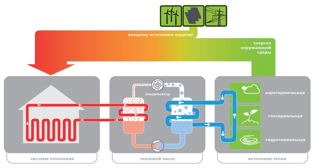
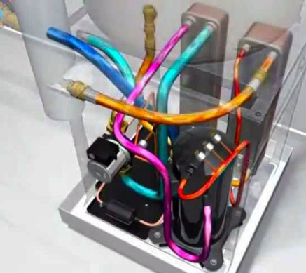
The device has an external and internal circuit along which the coolant moves. The components of a standard appliance are a heat pump, an intake device and a heat distribution device. The internal circuit consists of mains powered compressor, evaporator, throttle valve, condenser. Fans, a pipe system, and geothermal probes are also used in the device.
Heat pump advantages:
- does not highlight any harmful substances, absolutely eco-friendly;
- there are no costs for the purchase and delivery of fuel (electricity is spent only on moving freon);
- no need for additional communications;
- absolutely fire - and explosion-proof;
- full heating in winter and air conditioning in summer;
- a self-built heat pump is an autonomous design that requires a minimum of control effort.
Application
A hand-assembled heat pump is suitable for such cases:
- if there is a desire to save on fuel for heating the house;
- if it is impossible to supply gas to the house or it is too troublesome when to buy bottled gas- not a way out of the situation;
- there is no desire and opportunity to heat with coal, firewood, electricity, other fuel;
- if the owner of the house is committed to the use of environmentally friendly alternative energy. The device is quite practical, even along with the availability of opportunities to use other energy sources.
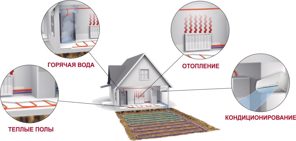
A do-it-yourself heat pump is made for the home, based on technologies for taking heat from the earth, water, and air. It is used for heating, water heating and even indoor air conditioning.
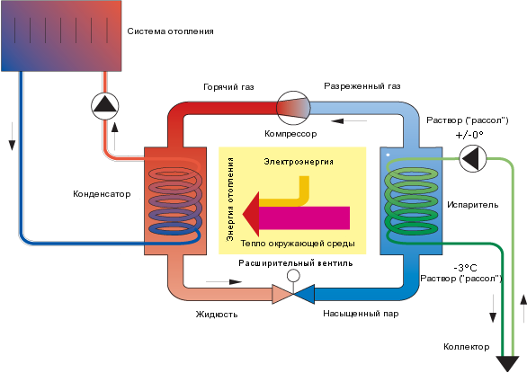
Principle of operation
All the space around us is energy - you just need to know how to use it. For heat pump it is necessary that the temperature environment was more than 1°C. Here it should be said that even the earth in winter under snow or at some depth retains heat. The work of a geothermal or any other heat pump is based on the transportation of heat from its source using a heat carrier to the heating circuit of the house.
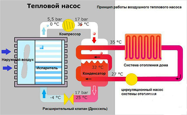
Scheme of operation of the device by points:
- the heat carrier (water, soil, air) fills the pipeline under the soil and heats it;
- then the coolant is transported to the heat exchanger (evaporator) with subsequent heat transfer to the internal circuit;
- the external circuit contains the refrigerant, a liquid with a low boiling point under low pressure. For example, freon, water with alcohol, glycol mixture. Inside the evaporator, this substance is heated and becomes a gas;
- gaseous refrigerant is sent to the compressor, compressed under high pressure and heats up;
- hot gas enters the condenser and there its thermal energy is transferred to the house;
- the cycle ends with the conversion of the refrigerant into a liquid, and it, due to heat loss, returns back to the system.
The same principle is used for refrigerators, so home heat pumps can be used as air conditioners to cool a room. Simply put, a heat pump is a kind of refrigerator with the opposite effect: instead of cold, heat is generated.
Kinds
Do-it-yourself heat pumps can be designed based on three principles - according to the energy source, the coolant and their combination. The source of energy can be water (reservoir, river), soil, air. All types of pumps are based on the same operating principle.
Classification
There are three groups of devices:
- water-water;
- groundwater (geothermal heat pumps);
- use water and air.
Thermal collector "ground-water"
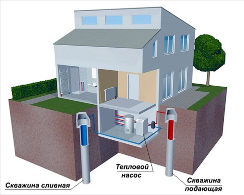
Do-it-yourself heat pump is the most common and effective method energy extraction. At a depth of several meters, the soil has one constant temperature and is little affected by weather conditions. On the outer contour of this, a special environmentally friendly liquid is used, popularly called "brine".
The outer contour of the geothermal pump is created from plastic pipes. They are dug into the ground vertically or horizontally. In the first case, one kilowatt may require a fairly large area of work - 25–50 m2. The area cannot be used for planting - only planting annual flowering plants is allowed here.
A vertical energy collector requires several wells of 50–150 m. Such a device is more efficient, heat is transferred by special deep probes.
At great depths, the water temperature is constant and stable. The source of low-potential energy can be an open reservoir, groundwater (well, well), wastewater. There are no fundamental differences in the design for heating of this type with different heat carriers.
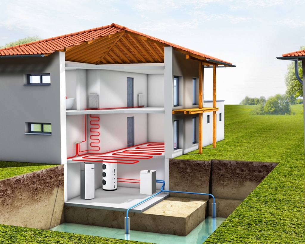
The “water-water” device is the least labor-intensive: it is enough to equip pipes with a heat carrier with a load and place them in water if it is a reservoir. For ground water more complex structure and there may be a need to build a well for the discharge of water passing through the heat exchanger.
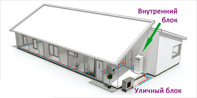
"Air-water"
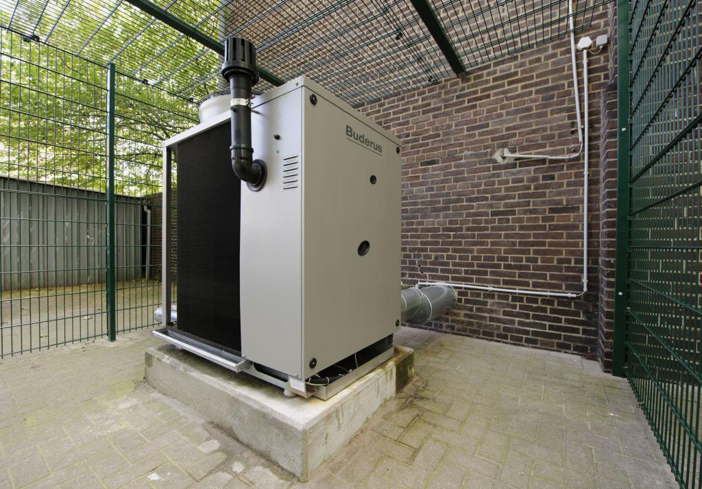
Such a pump is slightly inferior to the first two and in cold weather its power decreases. But it is more versatile: it does not need to dig the ground, create wells. You only need to install necessary equipment, for example, on the roof of the house. This does not require complex installation work.
The main advantage is the ability to reuse the heat leaving the room. In winter, it is recommended to have another source of heat, since the power of such a heater can be significantly reduced.
Installation steps
A do-it-yourself heat pump can be made entirely from old parts, taken, for example, from a non-working air conditioner.
Costs, payback, power
A factory-made device costs about 4,000 euros and more. Homemade pump for heating 100 m² of area will pay for itself after approximately 2 years. For houses with not very good thermal insulation, the power should be 75 W / m²., With good thermal insulation, 50 W / m² is enough, and when using modern thermal insulation materials- 30 W / m² is enough.
The ideal option would be when the pump is included in a project for heating a house with underfloor heating and tile flooring.
Process of creation
First you need to get the compressor from a non-working air conditioner, not necessarily a new one. It will be cheaper to purchase it in refrigerator repair shops. The compressor is attached to the wall with brackets (L-300 will do).
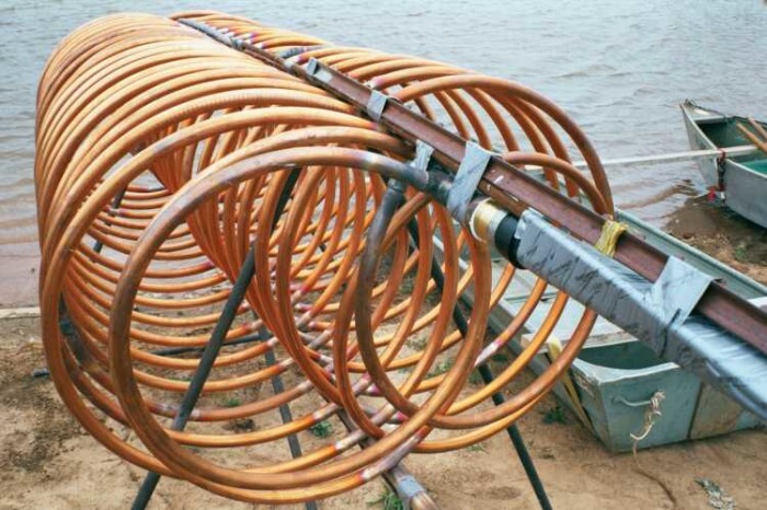
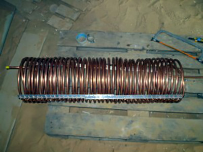
For the manufacture of a capacitor, a stainless steel tank of 100-120 liters is suitable. It is cut in half, a coil is installed inside. The coil can be made by yourself from plumbing or from the refrigerator. Here you need thick walls - from 1 mm and more. The tube is wound on a conventional cylinder (gas, oxygen) with uniform distance between the turns and is fixed in this position by a perforated aluminum corner(they make out the corners under the putty). It is attached to the coil so that each turn is located against the hole in the corner.
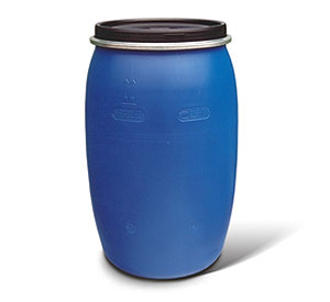
The result will be an even pitch of turns and structural strength. After creating the coil, the halves of the container are welded. Threaded connections are also welded. Then an evaporator is created. An ordinary plastic container of 60–80 liters may be suitable for it. with a ¾ inch pipe coil mounted inside. Simple pipes for plumbing is used to transport water.
The evaporator is mounted on the wall with an L-bracket. But the injection of freon should be done by a specialist in refrigeration equipment: he will weld the tubes and pump freon into them. After that, the structure is connected to the heating system inside the house, and then to the external circuit.
Features for each species
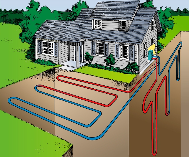
A vertical ground-to-water heating pump requires a 50–150 m well. Geothermal probes are placed in it and connected to the pump. The probes take heat from the ground, which is transferred with non-freezing water to the pump, and from there to the heating system. For small areas, probes are suitable, for large areas, a horizontal collector.
For a horizontal apparatus of the "soil-water" type, you need to create a collector from a pipe system. It is located below the freezing level (1–1.5 m) and looks like a kind of serpentine underground. A layer of soil is removed, pipes are laid and the soil is poured back. It is possible to lay pipes in separate trenches.
For a water-to-water unit, it is assembled from HDPE pipes, which are filled with a heat carrier and then transferred to a reservoir. The pipes look like a large serpentine at the bottom of the reservoir. It is advisable to place them in its center.
The air-to-water apparatus does not require labor-intensive earthworks. A place is chosen near the house or on its roof, where a home-made heat pump is connected to the house heating. Heat is extracted by fans and an evaporator.
Today, few people doubt that a heat pump for home heating is the most effective remedy from all existing ones. It is also the most expensive and difficult to perform. For this reason, many home craftsmen took up independent solution this problem. But in view of its high complexity, achieving positive results is very difficult, you need to have enthusiasm, patience and, in addition, study the theory well. Our article is for those who are taking the first step towards introducing such alternative source energy like a DIY heat pump.
Device and principle of operation
To assemble a working model of a heat pump, one cannot do without knowledge of the theory, or rather, the principle of operation of this device. I would like to initially note that the statements about the efficiency of 300, 500 and 1000% are a myth or just a marketing ploy, calculated on the ignorance of the ordinary user of the laws of physics. So, a heat pump is a device that takes thermal energy in one place and moving it to another with a certain efficiency not exceeding 100%. Unlike boiler plants, it does not produce heat on its own.
An example is home refrigerators and air conditioners, whose design is based on the so-called Carnot cycle, which also uses the principle of a heat pump for heating or hot water. The essence of this cycle is the movement of a substance (working fluid) along closed system and changing its state of aggregation from liquid to gaseous and vice versa. At the moment of transition, a huge amount of energy is released or absorbed.
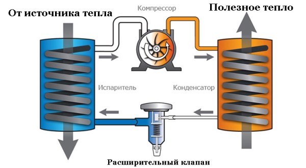
To explain in a more accessible language, we list the main elements that the heat pump device includes:
- compressor;
- a heat exchanger where the working fluid passes into a gaseous state (evaporator);
- a heat exchanger in which the working fluid is condensed (condenser);
- expansion (reducing) valve;
- controls and automation;
- highways from copper tubes.
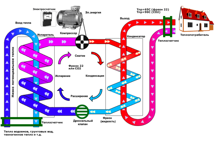
The working fluid is a substance that boils at low temperatures - freon. Circulating through the tube in the form of a liquid, first of all it enters the evaporator. After interaction with the coolant from external source(air, water, soil) the working fluid evaporates and continues its movement in the form of a gas. In this area, the pressure in the system is low. The entire cycle chain is reflected in the heat pump circuit diagram:
After passing through the compressor, freon moves under pressure to the second heat exchanger, where it has to condense and transfer the received heat to water, again assuming a liquid state. Further, the working fluid enters the expansion valve, the pressure drops again and it continues on its way to evaporation. The cycle is complete.
Factory heat pumps for a residential building are capable of delivering a coolant with a temperature of 55-60 ºС, this is enough to heat the premises with radiators or warm floors. At the same time, the entire heating system consumes electricity for the following purposes:
- compressor power;
- rotation of the rotors of the circulation pumps of the external and internal circuits;
- power supply for automation and control equipment.
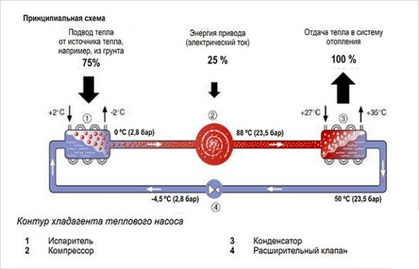
It turns out that when consuming 1 kW of electricity, the action of a heat pump can move up to 5 kW of thermal energy from the outside into the house, hence the fables about the efficiency of 500%.
Air-to-air heat pump
Theoretically, any medium that has a temperature above absolute zero (minus 273 ºС) has a reserve of thermal energy. This means that it can be removed, even more so it is not difficult to do this at an ambient temperature of minus 10-30 ºС.
For this purpose, an air-to-air heat pump is used, which takes heat from the external environment and moves it inside a private house. This is the most affordable way at the price of equipment and the cost of installation, it is also the least effective. The colder it is outside, the less heat you can get. The principle of operation of the system is shown in the figure:
The outdoor unit of an air source heat pump is similar in appearance to the same unit of a split system, only inside it does not have a compressor. All that remains is a plate heat exchanger and a fan, whose task is to increase the intensity of the process by forcing through the plates a large number air.
Heat pump water-to-water
A more efficient option is a water-to-water heat pump. It extracts thermal energy from the nearest body of water, if there is one at a distance of up to 100 m from the house. Another, more common method is the extraction of heat from groundwater through a well. In fact, 2 wells are needed: one for pumping water, the other for dumping it. Below are diagrams of heat pumps operating on this principle:
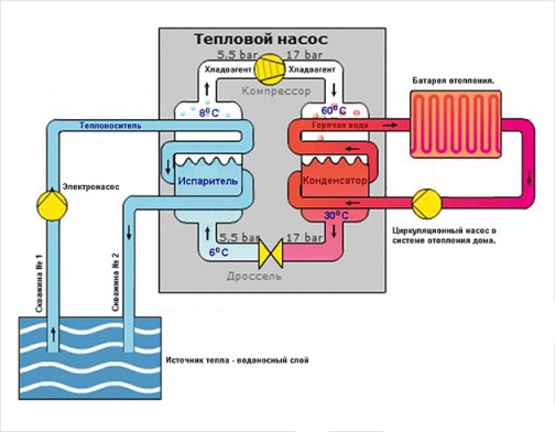
There are some nuances here. Water from the well must be treated before entering the heat exchanger, and pipes must be laid below the freezing depth of the soil. Another thing is the circuit at the bottom of the reservoir, it is filled with a non-freezing liquid (propylene glycol), which serves as an intermediary between water and refrigerant.
Important. Ability to provide a private house thermal energy in this case depends on the productivity of the well and the volume of water in the pond. There are also options for immersing the external circuit in the running water of a river or a sewer septic tank.
There are also geothermal heat pumps, whose principle of operation does not differ from previous types of devices, only heat is extracted from the ground at a depth where the temperature is always the same - plus 7 ºС. To do this, a horizontal contour of pipes is buried in the ground, occupying a large area, or geothermal probes are lowered into wells 25 m deep. In both cases, antifreeze is used as a coolant.
It is believed that the operation of a heat pump that extracts heat from the ground is the most stable and efficient. But the purchase and installation of such equipment is very expensive, and home craftsmen rarely resort to implementing this option.
How to assemble a heat pump at home?
Since the thermodynamic calculation of a heat pump is a considerable difficulty for most home craftsmen - do-it-yourselfers, we will not present it here. Our task is to present several working models so that any enthusiast can take one of them as a basis for creating their own offspring.
It should be noted that a heat pump, invented and assembled by oneself, will remain an unattainable dream for the vast majority of ordinary users if a lot of effort and time are not put into its manufacture.
The simplest heat pump from an old refrigerator was described in an article in the magazine "Engineer" for 2006. It is positioned as an air-to-air heater for a small room or greenhouse. By the way, no matter how powerful household refrigerator, for heating even small house it is not enough, but for 1 room - quite. The solution is implemented in 2 ways, whereby the internal automatic shutdown is dismantled and all units are connected directly for continuous operation. In the first case old refrigerator located indoors, the design of the pump is shown in the diagram:
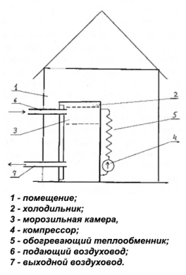
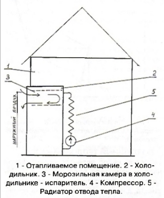
Outside, 2 air ducts are laid to it and crashes into the front door. The air through the upper channel enters the freezer, cools and descends to the lower air duct due to an increase in density. It then leaves the refrigerator body, displaced by the upper flow. The room is heated by a heat exchanger located on the back wall unit. According to the second method, making a heat pump with your own hands is just as simple, you just need to build a refrigerator into outer wall, as shown in the diagram:
A home-made heater from the refrigerator can function up to an outside temperature of minus 5 ºС, not lower.
Heat pump from air conditioner
Modern split systems, especially inverter type, successfully perform the functions of the same air-to-air heat pump. Their problem is that the efficiency of work falls along with the outside temperature, and even the so-called winter set does not save.
Home craftsmen approached the issue differently: they assembled a home-made heat pump from an air conditioner that takes heat running water from the well. In fact, only the compressor is used from the air conditioner, sometimes - indoor unit playing the role of a fan coil.

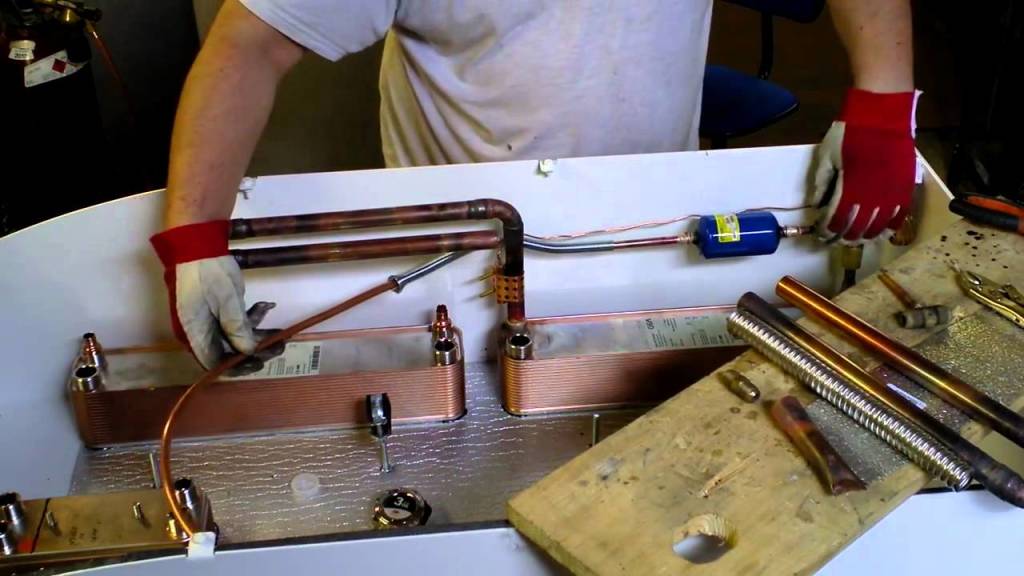
By and large, the compressor can be purchased separately. It will need to make a heat exchanger for heating water (condenser). A copper tube with a wall thickness of 1-1.2 mm and a length of 35 m is wound to form a coil on a pipe with a diameter of 350-400 mm or a cylinder. After that, the turns are fixed with a perforated corner, and then the whole structure is placed in a steel container with water pipes.
The compressor from the split system is connected to the lower input to the condenser, and the control valve is connected to the upper one. The evaporator is made in the same way, the usual plastic barrel. By the way, instead of homemade capacitive heat exchangers, you can use factory plate heat exchangers, but this will not be cheap.
The assembly of the pump itself is not too complicated, but here it is important to be able to properly and efficiently solder the copper tube connections. Also, to refuel the system with freon, you will need the services of a master, but you won’t specifically buy additional equipment. Next is the stage of setting up and starting up the heat pump, which does not always go well. You may have to tinker a lot to achieve the result.
Conclusion
Of course, heating your home with a heat pump is the dream of many homeowners. Unfortunately, the cost of installations is too high, and to cope with handmade units can. And then often there is enough power only for hot water supply, we are not talking about heating. If everything were so simple, then we would have a home-made heat pump in every house, but for now it remains inaccessible to a wide range of users.
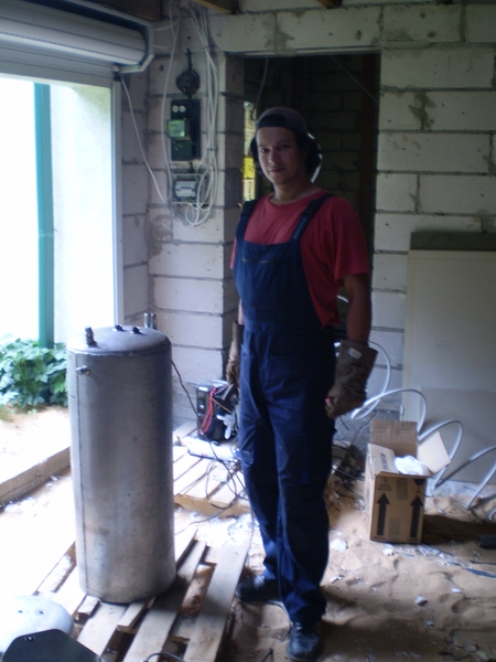
DIY heat pump
From the beginning, there was only a house under construction on 2.5 floors. Square:
1st floor 64 m2,
2nd floor 94 m2,
2.5 floor 55 m2,
garage 30 m2.
Bought secondhand from the start. gas generating boiler on firewood with a capacity of 40 kW But as the time for the installation approached, I completely ceased to please the prospect of harvesting firewood, the eternal struggle with garbage, and by nature I am more of a dervish, I can easily not appear at home for a couple of days.
(Homemade heat pump, gas generating boiler, Evaporator, compressor, Condenser, homemade heat pump, heat pump, DIY heat pump, alternative energy)
And then I leaned towards liquefied gas. Note that the natural gas pipe low pressure passes 1.5 km from the house. But our population density is low, and pulling a pipe for me alone + project + installation just plunges me into horror.
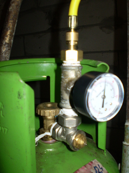
I also can’t put a barrel on several cubes on the site. I don't want to ruin the look. I decided to install a couple of cabinets with a battery of 80-liter propane tanks of 6 pieces each.
The gas operator assured that they themselves come, change themselves, you just call us. He referred only to inconvenience headache once every three weeks, as well as the possibility of an unauthorized entry of a gas car into my future cobblestone-passenger parking lot, rolling and dragging cylinders along it. In general, the human factor. But the case solved the problem:
idea to build DIY heat pump
idea construction heat pump hatched for a long time. But the stumbling block was single-phase electricity and an antediluvian meter for 20 amperes of maximum load. It is not yet possible to change the eclectic power supply to a three-phase one or add power in our area. But unexpectedly, they planned to change the meter to a new one, 40 amperes.
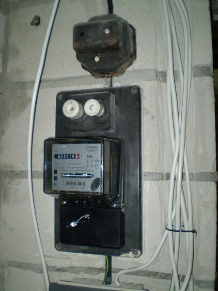
Having estimated, I decided that this would be enough for partial heating (I did not plan to use the 2.5th floor in winter), I undertook to probe the heat pump market. The prices requested in one company (single-phase HP for 12 kilowatts) made us think:
Thermia Diplomat TWS 12 kWh 6797 euros
Thermia Duo 12 kWh 5974 euros
It required at least 45 amps for starting current.
In addition, since it was planned to take heat removal from well water, there was no confidence in the debit of my well. In order not to risk such an amount, I decided to assemble the TN myself, since some skills were from life. He worked when he was a manager for the distribution of ventilation and air conditioning equipment.
Homemade heat pump concept:
I decided to make a HP from two single-phase compressors of 24,000 BTU each (7 kWh in cold). Thus, a cascade with a total thermal power of 16-18 kilowatts was obtained with electricity consumption at COP3 of about 4-4.5 kilowatts / hour. The choice of two compressors was due to lower starting currents, since it was thought not to synchronize their starts. As well as the phased commissioning. So far, only the second floor has been inhabited and one compressor will suffice. Yes, and having experimented on one, then it will be bolder to complete the second section.
Refused to use plate heat exchangers. Firstly, for reasons of economy, I did not want to pay 389 euros apiece for Danfos. And secondly, to combine the heat exchanger with the capacity of the heat accumulator, that is, by increasing the inertia of the system, thereby killing two birds with one stone. And I didn’t want to do water treatment for delicate plate heat exchangers, thereby reducing efficiency. And my water is bad, with iron.
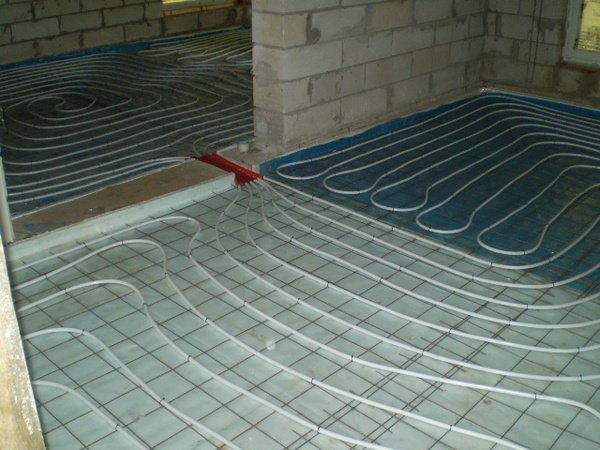
The first floor is already equipped with a heated floor piping with an approximate step of 15 cm.
The second floor has radiators (thank God, it was enough stinginess to put them with 1.5 thermal reserves earlier). Coolant intake from the well (12.5 m. Installed on the first layer of dolomite. +5.9 measured on 03.2008). Disposal of waste water into the general sewerage system (two-chamber sump + infiltration soil absorber). forced circulation in the heating circuits.
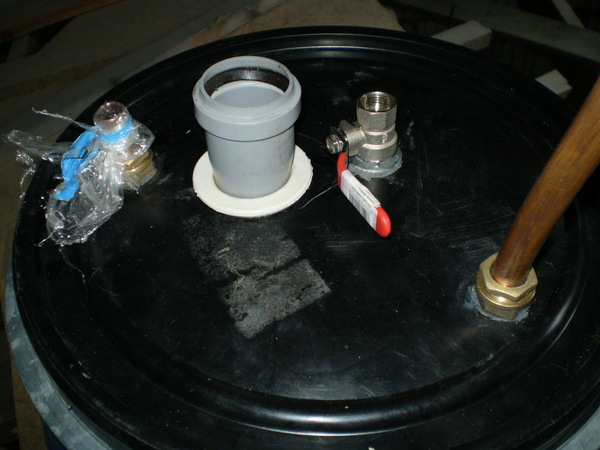
Here is the schematic:
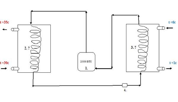
1. Compressor (so far one).
2. Capacitor.
3. Evaporator.
4. Thermal expansion valve (TRV)
It was decided to abandon other safety devices (filter-drier, viewing window, pressure switch, receiver). But if anyone sees the point of using them, I will be glad to hear advice!
To calculate the system, I downloaded the CoolPack 1.46 calculation program from the Internet.
And a good program for the selection of Copeland compressors.
Compressor:
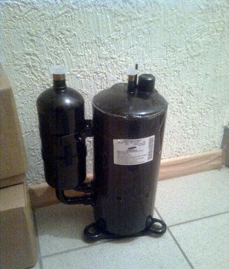
I managed to buy from an old friend of the refrigeration, a little used compressor from a 7 kilowatt split system of some kind of Korean air conditioner. I got it almost for nothing, and I didn’t lie, the oil turned out to be completely transparent inside, it worked for only a season and was dismantled due to a change in the concept of the premises by the customer.
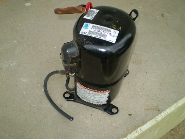
The compressor turned out to have a capacity of 25,500 Btu, which is about 7.5 kW. in cold and about 9-9.5 in heat. What made me happy, I was in the Korean split solid compressor American firm Tecumset. Here is his data:
Compressor on R22 freon, which means a slightly higher coefficient useful action. Boiling point -10c, condensation +55c.
Lapsus number 1: From old memory, I thought that only scroll type compressors (scroll) are installed on household split systems. Mine turned out to be piston ... (It looks a little oval and the engine winding is hanging inside). Bad, but not fatal. To its minuses, a quarter less resource, a quarter lower efficiency, a quarter more noisy. But nothing, experience is the son of difficult mistakes.
Important: Freon R22 under the Montreal Protocol will be fully decommissioned by 2030. Since 2001, the commissioning of new installations has been prohibited (but I am not introducing a new one, but have modernized the old one). Since 2010, the use of R22 freon is only used. BUT at any time you can transfer the system from R22 to its replacement R422. And no more trouble.
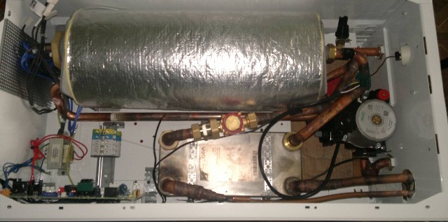
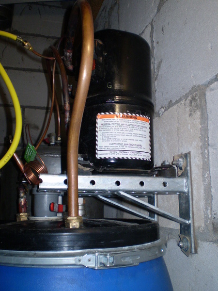
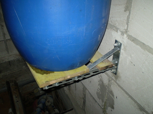
I fixed the compressor on the wall with L-300mm brackets. If I later mount the second one, I lengthen the existing ones using the U-profile.
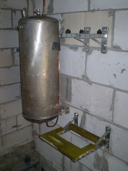
2. Capacitor:
I successfully purchased a stainless steel tank of about 120 liters from a welder friend.
(By the way, all welded manipulations with the tank were performed free of charge by a respected welder. But he asked to mention his modest role for history!)
It was decided to cut it into two parts, insert a coil from a copper pipe of a freon guide, and weld it back. At the same time, weld in several technical inch-threaded connections.
The formula for calculating the surface area of a copper coil pipe:
M2 = kW/0.8x?t
M2 is the area of the coil pipe in square meters.
kW - Heat dissipation power of the system (with compressor) in kilowatts.
0.8 - coefficient of thermal conductivity of copper / water under the condition of counterflow of media.
T is the difference between the water temperature at the inlet and outlet of the system (see diagram). For me it is 35s-30s = +5 degrees Celsius.
So it turns out about 2 square meters coil heat exchange area. I slightly reduced it, since the temperature at the freon inlet is about + 82 ° C, this can save a little. But as I wrote earlier Santa Claus, not more than 25% of the size of the evaporator!!!
The simulated system in CoolPack showed a Cop of 2.44 on stock heat exchanger tube diameters. And Cop 2.99 with a diameter one step higher. And this is to my advantage, since in the future I expect to attach a second compressor to this branch. Decided to use copper pipe½” inch (or 12.7mm OD) refrigerated. But, I think, you can use the usual plumbing, it’s not like that there and there will be a lot of dirt inside.
Lapsus number 2: I used a pipe with a wall of 0.8 mm. In fact, she turned out to be very gentle, a little crushed and she already hesitates. It is difficult to work, especially without special skills. Therefore, I recommend taking a 1mm or 1.2mm wall pipe. So the durability will be longer.
Important: The freon conductor of the coil enters the condenser from above, exits from below. So condensing liquid freon will accumulate at the bottom and leave without bubbles.
Thus, having taken 35 meters of the pipe, he turned it into a coil, winding it around a convenient cylindrical object (cylinder).
At the edges, I fixed the turns with two aluminum slats for strength and equal spacing of the loops.
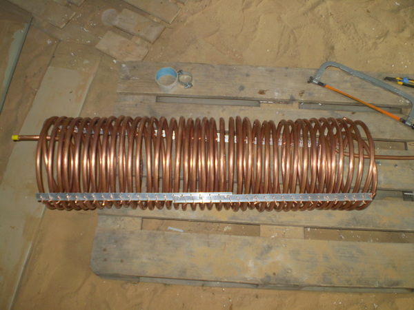
The ends were brought out with the help of plumbing transitions to a copper tube for twisting. He slightly drills them from a diameter of 12 to 12.7 mm, and instead of a compression ring, after assembly, he wound flax on a sealant and clamped it with a lock nut.
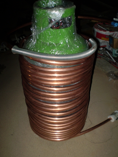
3. Evaporator:
No evaporator required high temperature, and I chose a plastic container like a 127 liter barrel with a wide mouth.
Important: A 65 liter barrel would be ideal. But I was afraid, the ¾ pipe bends very badly, so I took a larger size. If anyone has other sizes or has a good pipe bender and work skills, then you can take a chance on this size. With a 127 liter drum, my HP increased the expected dimensions by 15 cm up, 5 cm deep and 10 cm wide.
I calculated and manufactured the evaporator according to the same principle as that of the condenser. It took 25 meters of pipe ¾ 'inch (19.2mm outer) with a wall of 1.2mm. As stiffening ribs, I used segments of the UD profile for the installation of gypsum plaster. Twisted with ordinary copper electrical wire without insulation.
Important: Flooded type evaporator. That is liquid phase freon enters the cooled water from below, evaporates and in a gaseous state rises up to the compressor. This is better for heat transfer.
Transitions can be taken from plastic drinking pipes PE 20 * 3/4 'with an external thread, unscrewed from the barrel with lock nuts and a seal made of flax and sealant. Water supply and drainage made from ordinary sewer pipes and rubber sealing cuffs inserted by surprise.
The evaporator was also mounted on L-400mm brackets.
4. TRV:
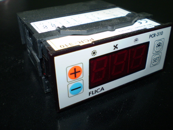
Acquired TRV from Honeywell (former FLICA). For my power, it took a 3mm nozzle to it. And a pressure equalizer.
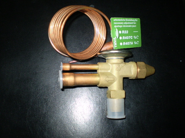
Important: TRV during soldering cannot be overheated above +100c! Therefore, I wrapped it with a cloth soaked in water to cool it. Please do not be horrified, after the raid I cleaned it with fine sandpaper.
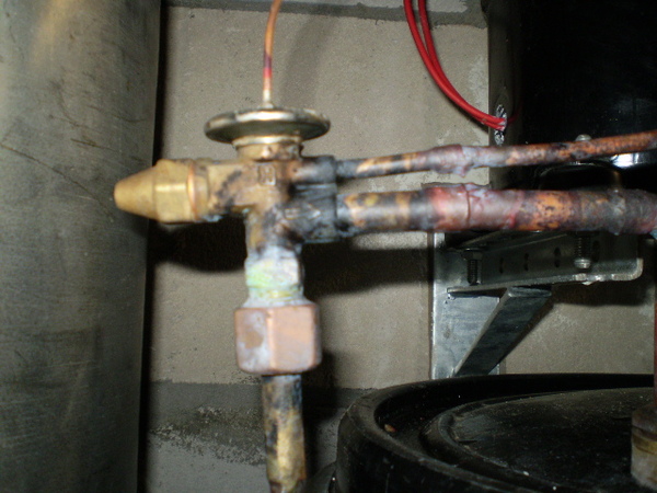
I soldered the equalization line tube as it should be in the installation instructions for the expansion valve.
Assembly:
Bought a kit for hard soldering Rotenberg. And electrodes 3 pieces with 0% silver content and 1 piece with 40% silver content for soldering in the compressor side (vibration resistant). With their help, I assembled the entire system.
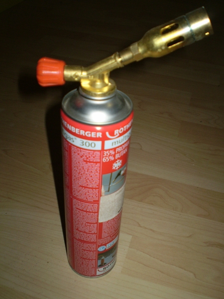
Important: Take the Maxigaz 400 bottle (yellow bottle) right away! It is not much more expensive than Multigas 300 (red), but the manufacturer promises up to +2200c flame. But this is not enough for ¾ 'pipe. Soldered badly. I had to contrive, use a heat shield, etc. Ideally, of course, have an oxygen burner.
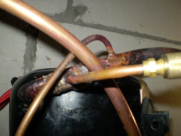
Yes, and you need to solder a filling pipe with a nipple to connect the hose to the system. I don't remember its exact name off the top of my head.
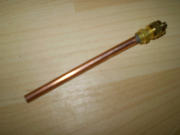
It was soldered at the compressor inlet. Nearby, the inlet pipe of the equalizer of the expansion valve is also visible. It is soldered after the evaporator, thermostatic expansion valve, but before the compressor.
Important: We solder the filling pipsik by first unscrewing the nipple from it. Neither from the heat, the nipple seal will definitely fail.
I did not use reducing tees, as I was afraid of a decrease in reliability from additional solder joints near the compressor. Yes, and the pressure in this place is not great.
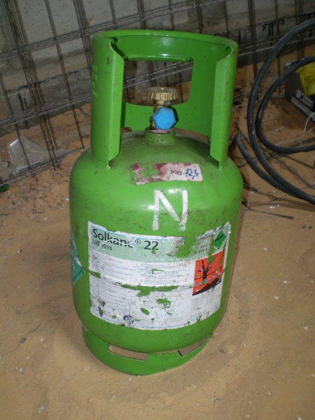
Freon charging:
collected, but not filled The system must be evacuated with water. Better to use Vacuum pump if not, then the craftsmen adapt a conventional compressor from an old refrigerator. You can simply blow through the system with freon by squeezing out the air, but I didn’t tell you this, because you can’t do that!
Freon cylinder of the smallest capacity. The system will not need more than 2 kg at all. freon. But how rich.
I also bought a pressure gauge. But not a special freon one for $ 10, but a regular one for pumping station for 3.5 USD On it and guided when filling.
I filled the system as much as possible with the help of the internal pressure of freon in the cylinder. I let it stand for a couple of days, the pressure did not drop. So there is no leak. Additionally, I missed all the connections with soapy foam, it did not bubble.
Important: Since in my case the filling nipple is soldered immediately in front of the compressor (in the future, the pressure in this place will be measured when setting up), in no case should the system be filled with liquid freon with the compressor running. The compressor will probably fail. Only in the gaseous phase - balloon up!
Automation:
You need a single-phase starting relay, and at the same time, for a very decent starting current of about 40 A! Automatic fuse From the group to 16A. Electrical panel with DIN rail.
I also installed two temperature switches with copelar thermal sensors. One put on the water at the outlet of the condenser. I set it to about 40 degrees to turn off the system when the water reaches this temperature. And to the outlet of water from the evaporator to 0 degrees, so that it emergency shuts down the system and does not unfreeze it by chance.
In the future, I'm thinking of purchasing a simple controller that takes these two temperatures into account. But apart from appearance and clarity of use, it also has a drawback - the programmed values are lost even with a short power outage. While thinking.
Run (trial):
Before starting, I pumped about 6 bar of pressure from the cylinder into the system. More did not work, and there is no need. I threw a temporary wire, connected the starting capacitor. I filled the containers with water first. They stood for a day, filled and therefore, at the time of launch they had room temperature about +15s.
Solemnly turned on the machine. He was knocked out immediately. Still, the same. During this short interval, you can hear the engine buzzing, but not starting. I moved the terminals on the capacitor (for some reason there are three of them). Turned the machine back on. The pleasant rumble of a running compressor caressed my ears!!!
The suction pressure immediately dropped to 2 bar. Opened the freon bottle to fill the system. According to the plate, I calculated the required boiling pressure of freon.
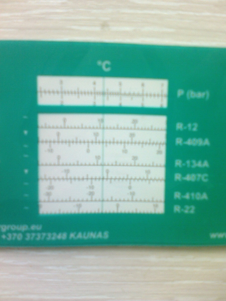
For my required +6 inlet and +1 outlet water, a boiling point of -4c is required. Freon boils at this temperature at a pressure of 4.3 kg.cm. (bar) (atmospheres). The table can also be found online.
No matter how I tried to set the exact pressure, nothing worked. The system has not yet been brought to operating temperature. Therefore, premature adjustments are only approximate.
Five minutes later, the feed reached about +80 degrees. While the uninsulated evaporation pipe was covered with light frost. The water in the condenser after ten minutes to the touch has already warmed up to +30 - +35. The water in the evaporator is close to 0c. In order not to unfreeze something, I turned off the system.
Summary: Trial run showed full working capacity systems. Anomalies were not observed. Further adjustments of the expansion valve and freon pressure will be required after connecting the heating circuit and cooling with well water. That's why continuation of the photo essay and report in about two to three weeks when I figure out this part of the work.
By that time, I think:
1. Connect the space heating circuit and the well water heat exchange circuit.
2. Produce full cycle commissioning works.
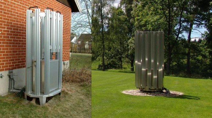
3. Make some kind of case.
4. Draw conclusions and give a short summary.
Important: TN turned out not so small in size. By using plate heat exchangers instead of capacitive heat exchangers, you can save a lot of space.
The cost of manufacturing a heat pump with an approximate capacity of 9 kilowatt hours in terms of heat:
Capacitor:
Stainless steel tank 100 liters - 25 c.u.
Stainless steel electrodes - 6 c.u.
Couplings stainless steel - 5 c.u.
Services of a welder (lunch) - 5 c.u.
Copper pipe 12.7 (1/2”)*0.8mm. 35 meters - 105 USD
Copper pipe 10*1 mm. 1 meter - 3 c.u.
Air blower Du 15 - 5 c.u.
Safety valve 2.5 bar - 4 c.u.
Drain valve Du 15 - 2 c.u.
Total: $163 (in comparison, plate heat exchanger Danfos 389 c.u.)
Evaporator:
Plasma barrel. 120 liters - 12 c.u.
Copper pipe 19.2 (3/4”)*1.2mm. 25 meters - 130 USD
Copper pipe 6*1mm. 1 meter - 2 c.u.
Honeywell thermostatic valve (nozzle 3mm) - 42 USD
Brackets L-400 2 pieces - 9 c.u.
Drain valve Du 15 - 2 c.u.
Transitions to copper (set) - 3 c.u.
RVS pipe 50-1m. 2 pieces - 4 c.u.
Rubber transitions 75*50 2 pieces - 2 c.u.
Total: $206 (in comparison, plate heat exchanger Danfos 389 c.u.)
Compressor:
Compressor little used 7.2 kW (25500 btu) - 30 c.u.
Brackets L-300 2 pieces - 8 c.u.
Freon R22 2 kg. - 8 c.u.
Mounting kit - 4 c.u.
Total: $50
Mounting kit:
Blowtorch ROTENBERG (set) - 20 USD
Hard soldering electrodes (40% silver) 3 pieces - 3.5 c.u.
Hard soldering electrodes (0% silver) 3 pieces - 0.5 c.u.
Manometer for freon 7 bar - 4 c.u.
Filling hose - 7 c.u.
Total: $35
Automation:
Starter relay single-phase 20 A - 10 c.u.
Built-in electric shield - 8 c.u.
Single-phase fuse C16 A - 4 c.u.
Total: $22
Total in general 476 c.u.
Important: Required for the next step circulation pumps Calpada 25/60-180 $60 and Calpeda 32/60-180 78 c.u. Although they will be taken out of the chapels of my boiler, they usually refer to the boiler itself.
Heat pump, alternative energy, heating, energy saving, do-it-yourself heat pump, homemade heat pump
Increasing the efficiency of the heating system at home is one of the main tasks of its owner, since the costs of this item in Russian climatic conditions are very significant. Therefore, the task of using the energy of the surrounding space for heating is very interesting, constantly evolving and remains the subject of attention, especially in the community of "homemade". Assembling a heat pump with your own hands is quite accessible to a trained person, since this work does not present any particular difficulties, and there is no need to manufacture parts of a complex configuration.
The principle of operation of the device
It is based on collecting heat from the surrounding space and using it for the heating system of the house in order to reduce the cost of this function. Devices of this type are available in many homes, these are refrigerators, split systems and air conditioners. Some of them have a dual purpose, performing either heating or cooling of the premises at the user's choice, depending on the need.
The theoretical basis of such machines is the reverse Carnot cycle. But, without going into details, we will simply describe the process of operation of such a device.
Fig.1. circuit diagram operation of the heat pump in the heating network
The working fluid in such devices, as in refrigerators, is freon or ammonia, which is pumped into the heating circuit by a compressor. At the same time, the pressure inside the system rises sharply, since the outlet of the coolant is blocked by a throttle. The resulting heat warms the coolant in the heating system of the house, as a rule, the temperature reaches 64 ° C. The hot flow supplements the one circulating in the main heating network, reducing fuel consumption. At a certain pressure, the throttle opens and the working fluid enters the evaporator chamber. At the same time, its temperature decreases. Additional heat is obtained from the heat collection register. Then the cycle is repeated, as in the refrigerator device.
Calculation of system parameters
The power that a homemade heat pump will require can be calculated from the ratio:
R = ( k * v * T )/860, Where
R – power required to heat the room
k – coefficient for taking into account heat losses by the building (1 - a well-insulated room, 4 - a wooden barrack);
v - the total volume of the room to be heated;
T – the greatest temperature difference between the outside world and the internal space;
860 – conversion factor of the calculation result to kW from kcal.
As an example, we give a calculation for a house of 200 square meters with a ceiling height of 2.8 meters:
R \u003d 1 * 200 * 2.8 * (22 - -25) / 860 \u003d 560 * 47 / 860 \u003d 30.6 kW.
It is advisable to use a heat pump with a power reserve of 10 - 12%, that is, about 35 kW.
It is necessary to pay attention to such an indicator as the difference between the external and internal temperatures. If we take heated air from the surrounding space with a temperature of about 7 ° C, the difference will be (22 - 7) 15 degrees, and the heat pump power will be 9.8 kW. Compare these two indicators and feel the difference when using the heat of the surrounding space.
Part of the equipment
Outer loop
Pipes will be needed for the external circuit of the house heating unit. Metal products have the highest thermal conductivity (but not from of stainless steel), so it is better to use them for a heat collection system.
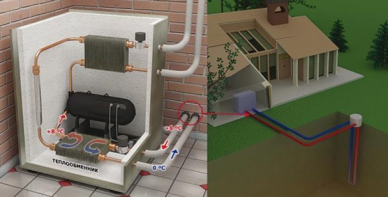
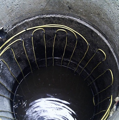
Fig.2. Collecting heat in the ground using a well for a homemade heat pump
Figure 2 shows a do-it-yourself ground source heat pump using parts from an old air conditioner and refrigerator. The depth of the well for collecting heat from geothermal waters is about 60 - 120 meters. The above diagram does not show the casing, but its use is mandatory, since the casing protects the walls of the well from destruction. The external heat collection register must be inside the casing.
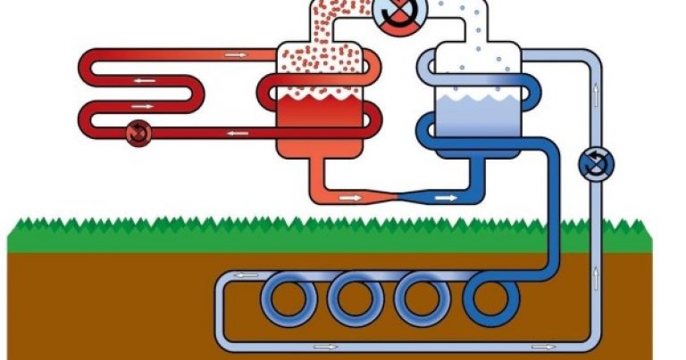
Fig.3. Surface collection of external heat
The collection of spatial energy for heating a house can be carried out not only through deep well, but also using horizontal system pipes buried no less than the amount of soil freezing.
A sufficient result is the collection of heat from the reservoir, since at the bottom the water temperature is always 4 degrees Celsius, since it is in this state that it has the highest density. The attractive side is a much smaller amount of excavation.
Used to collect heat and systems that heat up under the influence of the sun. Such blocks are most often installed on the roof of the house and are intended for heating water or air. They significantly increase the temperature in the evaporator of the heat pump, increasing the efficiency of the home heating system.
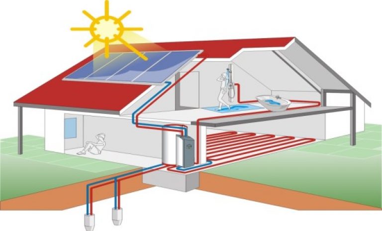
Fig.4. Using a solar collector in a building heating system with a heat pump
Evaporator
This node is a container in which the heat exchanger is located, which carries the heat carrier collected by the external circuit. The design of this part may be different, but most often it is made of copper pipes.
Rice. 5. The shape of the heat element of the evaporator should ensure maximum contact with the refrigerant
When making a heat pump with their own hands, they often use serviceable components and parts from an old refrigerator or air conditioner, as well as a broken split system.
Compressor
On self-made heat pumps, compressors are most often used from the available old technology. When the unit system is assembled and tested, you can think about replacing the compressor from the old refrigerator with another one, more or less powerful. When choosing a compressor, it is best to pay attention to the nodes from the split systems, which are characterized by increased power and reliability. Modern units are usually equipped with blocks automatic control and adjustment, which greatly simplifies the management of these units.

Fig.6. Heat pump compressor
Capacitor
The choice of this element of the system must be approached with particular care, since it is a pressure vessel. It is preferable to use the old gas bottle. It will have to be cut to place the heat exchanger there, and then welded again.
Chokes
In heat pumps, these are devices for relieving pressure from the condenser to the evaporator. The part is easy to find in stores or quarry repair shops, as they are very durable in operation.
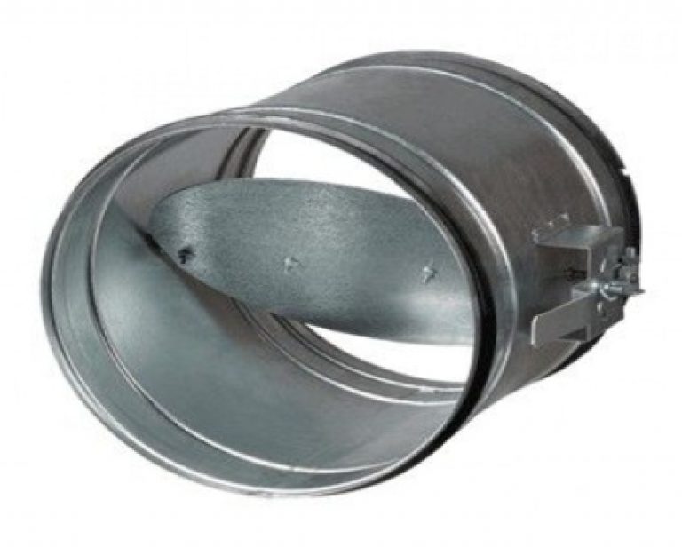
Fig.7. Throttle for heat pump
Frenetta heat pumps
These devices are extremely simple and effective. However, for their manufacture, the accuracy of the execution of each part and the careful balancing of the entire rotor system are important.
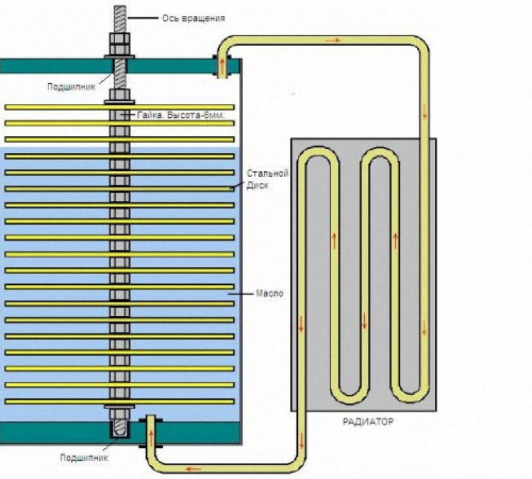
Fig.8. Frenette heat pump diagram
During operation of such a heat pump, oil is heated, and heat is transferred to the heating system of the house through a radiator. Vertical and horizontal layouts of the device are possible.
Do-it-yourself frenet heat pump for home heating can be made only with access to metalworking equipment and good locksmith training.
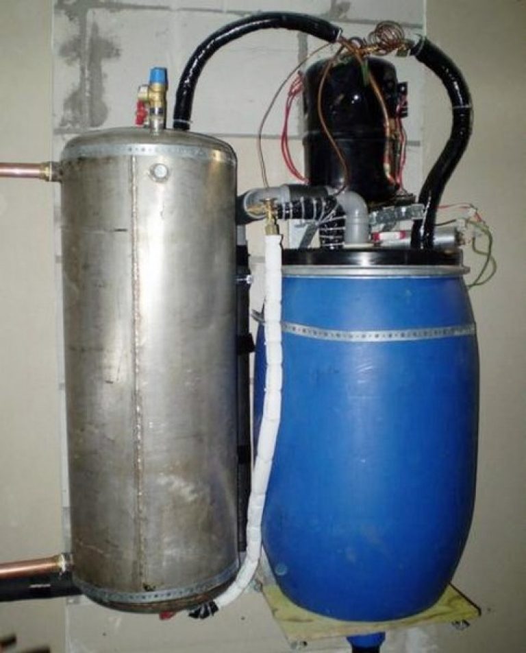
Fig.9. Version of the homemade heat pump
Conclusion
Using the energy of the surrounding space deserves attention, allowing you to reduce the cost of heating your home. When using the heat of geothermal waters or ground air heating, it will not pay off quickly due to the large labor and financial costs, however, the efficiency of the process is not in doubt.
In addition, it is possible to use heat pumps as split systems, increasing the comfort of living, and the use of an automatic control unit will facilitate device management.


